


Arduino Robot Car Wireless Control mit HC-05 Bluetooth, NRF24L01 und HC-12 Transceiver-Modulen
In diesem Tutorial lernen wir, wie man das Arduino-Roboterauto, das wir im vorherigen Video erstellt haben, drahtlos steuert. Ich zeige Ihnen drei verschiedene Methoden der drahtlosen Steuerung mit dem Bluetooth-Modul HC-05, dem Transceiver-Modul NRF24L01 und dem drahtlosen Modul HC-12 mit großer Reichweite sowie mit einem Smartphone und einer maßgeschneiderten Android-Anwendung. Sie können sich das folgende Video ansehen oder das schriftliche Tutorial unten lesen, um weitere Einzelheiten zu erfahren.
Ich habe bereits Tutorials, wie man jedes dieser Module mit dem Arduino-Board verbindet und verwendet. Wenn Sie also weitere Details benötigen, können Sie sie jederzeit überprüfen. Die Links zu jedem von ihnen finden Sie unten im Artikel.
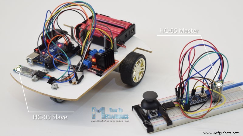
Wir beginnen mit der Bluetooth-Kommunikation und benötigen dazu zwei HC-05 Bluetooth-Module, die als Master- und Slave-Geräte konfiguriert werden müssen.
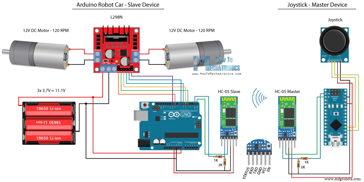
Wir können das ganz einfach mit AT-Befehlen tun, und ich habe den Joystick als Master und das Arduino-Roboterauto als Slave eingestellt. Hier ist der vollständige Schaltplan für dieses Beispiel:
Die für dieses Beispiel benötigten Komponenten erhalten Sie über die folgenden Links:
Wir werden denselben Code aus dem vorherigen Tutorial verwenden, in dem wir das Arduino-Roboterauto direkt mit dem Joystick steuern, und wir werden einige Änderungen daran vornehmen.
HC-05 Mastercode:
Der Code am Mastergerät oder am Joystick ist ganz einfach. Wir müssen nur die X- und Y-Werte des Joysticks lesen, die eigentlich die Geschwindigkeit der Motoren regeln, und sie über die serielle Schnittstelle an das Slave-Bluetooth-Gerät HC-05 senden. Wir können hier feststellen, dass die analogen Werte des Joysticks von 0 bis 1023 in Werte von 0 bis 255 umgewandelt werden, indem sie um 4 geteilt werden.
Wir tun dies, weil dieser Bereich von 0 bis 255 über das Bluetooth-Gerät als 1 Byte gesendet werden kann, was auf der anderen Seite oder am Arduino-Roboterauto leichter akzeptiert werden kann.
Also hier, wenn die Seriennummer die 2 Bytes, die X- und Y-Werte, mit der Funktion Serial.read() empfangen hat, werden wir beide lesen.
Jetzt müssen wir nur noch die Werte zurück in den Bereich von 0 bis 1023 umwandeln, passend für den Motorsteuerungscode unten, dessen Funktionsweise wir bereits im vorherigen Video erklärt haben.
Nur eine kurze Anmerkung, dass wir beim Hochladen des Codes die RX- und TX-Pins des Arduino-Boards trennen müssen.
Vollständiger HC-05-Slave-Code:
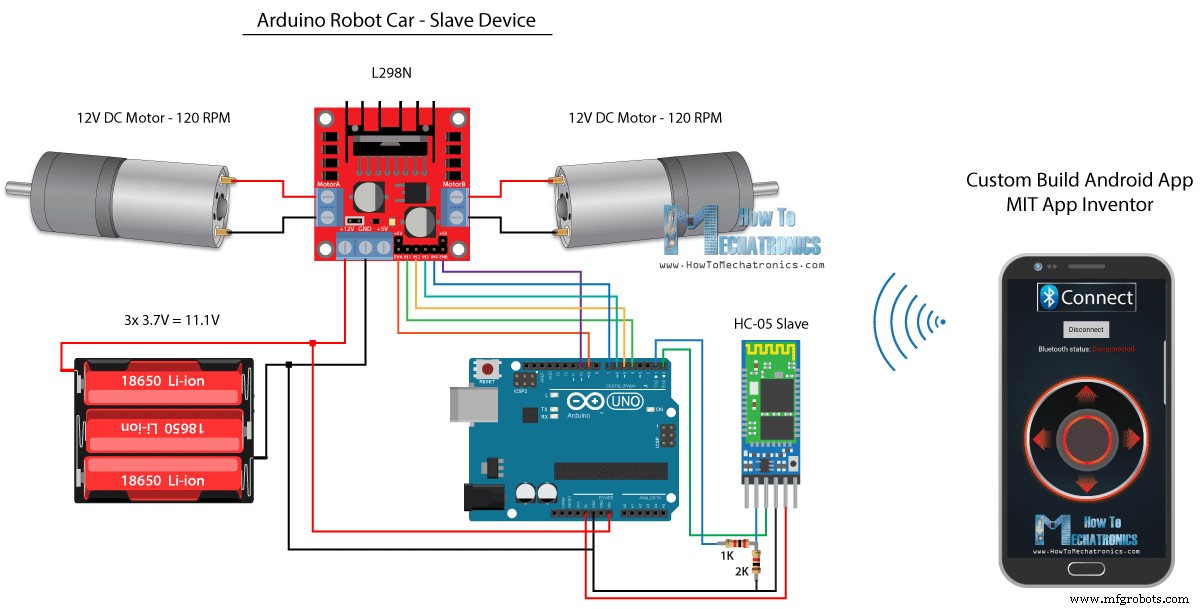
Als Nächstes sehen wir uns an, wie wir unser Arduino-Roboterauto mit einer speziell entwickelten Android-App steuern können. Der Schaltplan des Roboterautos ist genau derselbe wie im vorherigen Beispiel, wobei der HC-05 Bluetooth-Modus als Slave-Gerät eingestellt ist.
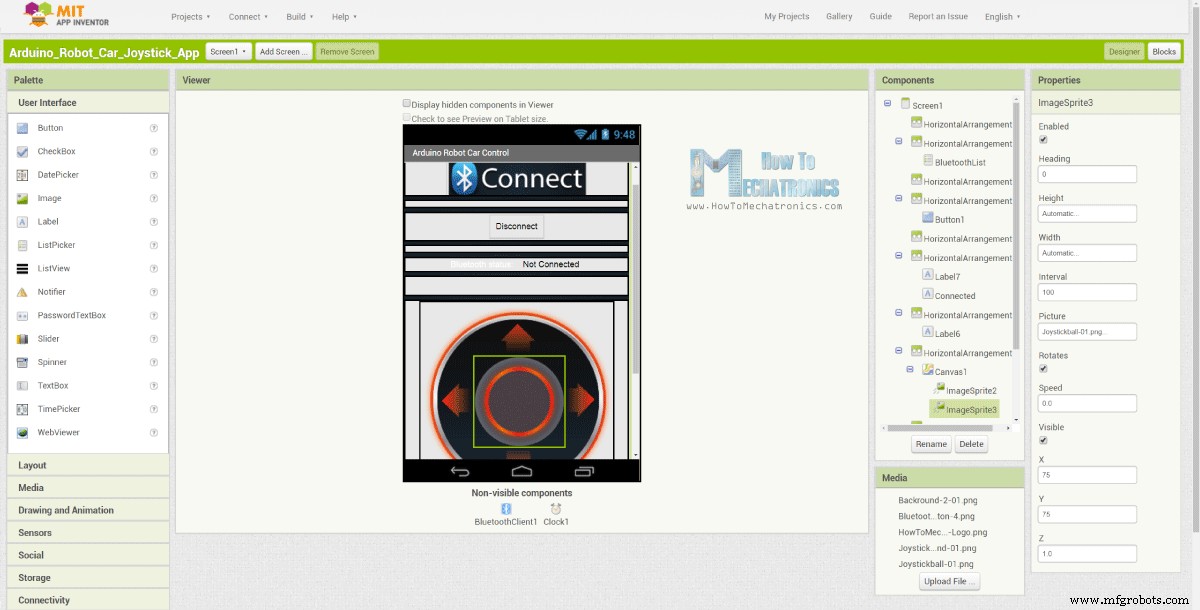
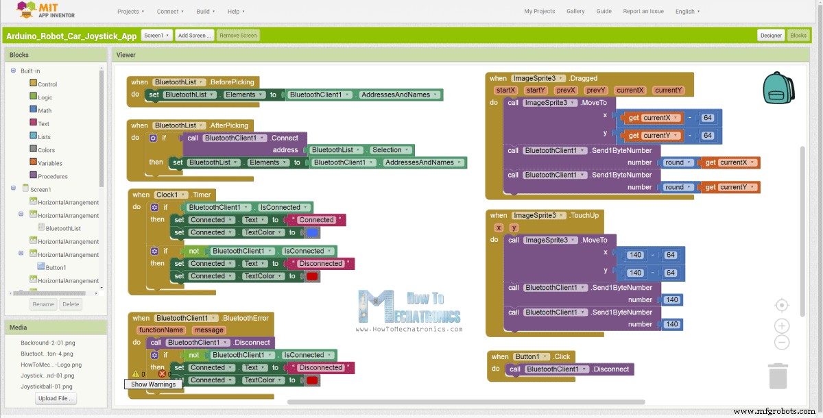
Andererseits werden wir mithilfe der Online-Anwendung MIT App Inventor unsere eigene Android-App erstellen, und so sieht sie aus.
Im Grunde simuliert die App also einen Joystick, dessen Aussehen aus zwei Bildern oder Bild-Sprites besteht.
Wenn wir uns die Blöcke dieser App ansehen, können wir sehen, dass beim Ziehen des Joystick-Sprites das Bild der Joystick-Kugel an die aktuelle Position unseres Fingers verschoben wird und wir gleichzeitig X und Y senden Werte über Bluetooth an das Arduino-Auto.
Diese Werte werden vom Arduino auf die gleiche Weise wie im vorherigen Beispiel mit der Serial.read-Funktion akzeptiert.
Was wir hier zusätzlich tun müssen, ist, die empfangenen X- und Y-Werte vom Smartphone in den Bereich von 0 bis 1023 umzuwandeln, passend für den unten stehenden Motorsteuercode. Diese Werte hängen von der Leinwandgröße ab, und die X- und Y-Werte, die ich von meiner App erhielt, lagen zwischen 60 und 220, die ich mit der map()-Funktion einfach umwandeln konnte.
Bei den Anwendungsblöcken können wir auch sehen, dass sich die Joystick-Kugel beim Berühren des Bild-Sprites zurück in die Mitte der Leinwand bewegt und entsprechende Werte an das Auto gesendet werden, um die Bewegung anzuhalten. Sie können diese App im Website-Artikel finden und herunterladen, ebenso wie die beiden Bilder des Joysticks, damit Sie Ihre eigene App erstellen oder diese App ändern können.
Sie können die Android-App unten sowie die beiden Bilder für den Joystick herunterladen:
Vollständiger Arduino-Code:
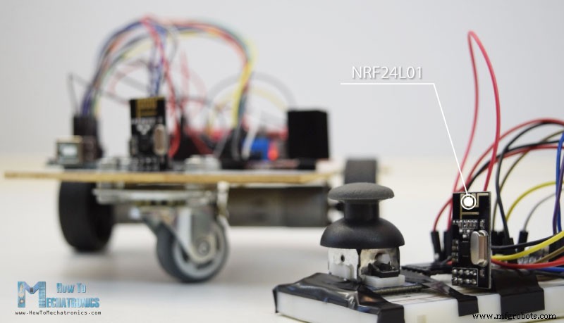
Jetzt können wir mit der nächsten Methode fortfahren, der drahtlosen Steuerung des Arduino-Roboterautos mit den NRF24L01-Transceiver-Modulen.
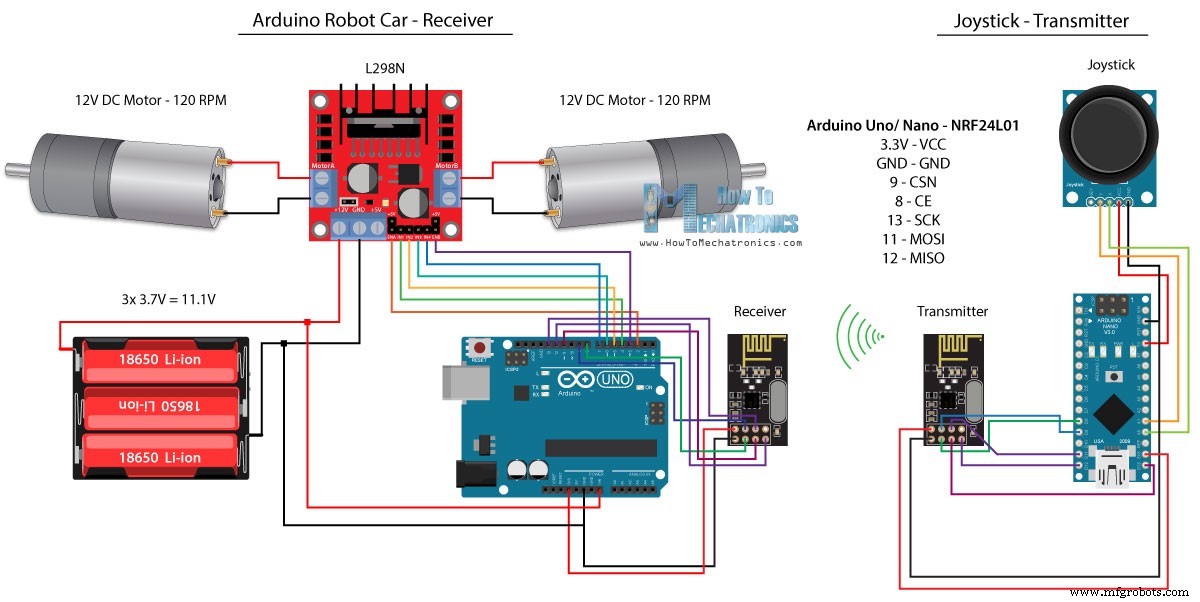
Hier ist der Schaltplan. Wir können feststellen, dass diese Module die SPI-Kommunikation verwenden, also musste ich im Vergleich zum vorherigen Beispiel die Pins Enable A und Enable B des L298N-Treibers auf die Pins Nummer 2 und 3 des Arduino-Boards verschieben. Sie können den NRF24L01 erhalten Modul unter folgendem Amazon-Link.
Für dieses Beispiel müssen wir die RF24-Bibliothek installieren. Ähnlich wie im vorherigen Beispiel lesen wir, nachdem wir einige Pins definiert und das Modul als Sender eingerichtet haben, die X- und Y-Werte des Joysticks und senden sie an das andere NRF24L01-Modul am Arduino-Roboterauto.
Zunächst können wir feststellen, dass analoge Messwerte Strings sind, die mit der Funktion string.toCharArray() in ein Zeichenarray eingefügt werden. Dann senden wir mit der Funktion radio.write() diese Zeichen-Array-Daten an das andere Modul.
Sendercode:
Auf der anderen Seite. Beim Arduino-Roboterauto akzeptieren wir, nachdem wir das Modul als Empfänger definiert haben, Daten mit der Funktion radio.read(). Dann wandeln wir mit der Funktion atoi() die empfangenen Daten oder die X- und Y-Werte vom Joystick in Integer-Werte um, die für den unten stehenden Motorsteuerungscode geeignet sind.
Es ist so einfach, aber natürlich, wie ich bereits sagte, wenn Sie weitere Details zum Anschließen und Einrichten der Module benötigen, können Sie jederzeit in meinem speziellen Tutorial nachsehen.
Empfängercode:
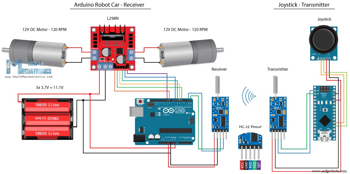
Für die letzte Methode der drahtlosen Steuerung des Arduino-Roboterautos verwenden wir die HC-12-Langstrecken-Transceiver-Module. Diese Module können über Entfernungen von bis zu 1,8 km miteinander kommunizieren.
Der Schaltplan für dieses Beispiel ist fast der gleiche wie für die HC-05 Bluetooth-Module, da sie die gleiche Methode für die Kommunikation mit dem Arduino über die serielle Schnittstelle verwenden.
Sie können das HC-12-Transceiver-Modul unter folgendem Amazon-Link herunterladen.
Der Joystick-Code ist genau derselbe wie der für die Bluetooth-Kommunikation. Wir lesen einfach die analogen Werte des Joysticks und senden sie mit der Funktion Serial.write() an das andere Modul.
Sendercode:
Auf der anderen Seite warten wir mit der while()-Schleife, bis die Daten ankommen, lesen sie dann mit der Funktion Serial.read() und konvertieren sie zurück in den Bereich 0 bis 1023, passend für den Motorsteuerungscode unten.
Empfängercode:
Das ist also so ziemlich alles für dieses Tutorial. Fühlen Sie sich frei, Fragen im Kommentarbereich unten zu stellen.Arduino Robot Car Control mit HC-05 Bluetooth-Modul
Quellcode
/*
   Arduino Robot Car Wireless Control using the HC-05 Bluetooth

                == MASTER DEVICE - Joystick ==

   by Dejan Nedelkovski, www.HowToMechatronics.com
*/

int xAxis, yAxis;

void setup() {
  Serial.begin(38400); // Default communication rate of the Bluetooth module
}

void loop() {
  xAxis = analogRead(A0); // Read Joysticks X-axis
  yAxis = analogRead(A1); // Read Joysticks Y-axis

  // Send the values via the serial port to the slave HC-05 Bluetooth device
  Serial.write(xAxis/4); // Dividing by 4 for converting from 0 - 1023 to 0 - 256, (1 byte) range
  Serial.write(yAxis/4);
  delay(20);
}
Codesprache:Arduino (arduino) // Code from the Arduino Robot Car
// Read the incoming data from the Joystick, or the master Bluetooth device
while (Serial.available() >= 2) {
x = Serial.read();
delay(10);
y = Serial.read();
} Codesprache:Arduino (arduino) // Code from the Arduino Robot Car
// Convert back the 0 - 255 range to 0 - 1023, suitable for motor control code below
xAxis = x*4;
yAxis = y*4; Codesprache:Arduino (arduino) /*
Arduino Robot Car Wireless Control using the HC-05 Bluetooth
== SLAVE DEVICE - Arduino robot car ==
by Dejan Nedelkovski, www.HowToMechatronics.com
*/
#define enA 9
#define in1 4
#define in2 5
#define enB 10
#define in3 6
#define in4 7
int xAxis, yAxis;
unsigned int x = 0;
unsigned int y = 0;
int motorSpeedA = 0;
int motorSpeedB = 0;
void setup() {
pinMode(enA, OUTPUT);
pinMode(enB, OUTPUT);
pinMode(in1, OUTPUT);
pinMode(in2, OUTPUT);
pinMode(in3, OUTPUT);
pinMode(in4, OUTPUT);
Serial.begin(38400); // Default communication rate of the Bluetooth module
}
void loop() {
// Default value - no movement when the Joystick stays in the center
x = 510 / 4;
y = 510 / 4;
// Read the incoming data from the Joystick, or the master Bluetooth device
while (Serial.available() >= 2) {
x = Serial.read();
delay(10);
y = Serial.read();
}
delay(10);
// Convert back the 0 - 255 range to 0 - 1023, suitable for motor control code below
xAxis = x*4;
yAxis = y*4;
// Y-axis used for forward and backward control
if (yAxis < 470) {
// Set Motor A backward
digitalWrite(in1, HIGH);
digitalWrite(in2, LOW);
// Set Motor B backward
digitalWrite(in3, HIGH);
digitalWrite(in4, LOW);
// Convert the declining Y-axis readings for going backward from 470 to 0 into 0 to 255 value for the PWM signal for increasing the motor speed
motorSpeedA = map(yAxis, 470, 0, 0, 255);
motorSpeedB = map(yAxis, 470, 0, 0, 255);
}
else if (yAxis > 550) {
// Set Motor A forward
digitalWrite(in1, LOW);
digitalWrite(in2, HIGH);
// Set Motor B forward
digitalWrite(in3, LOW);
digitalWrite(in4, HIGH);
// Convert the increasing Y-axis readings for going forward from 550 to 1023 into 0 to 255 value for the PWM signal for increasing the motor speed
motorSpeedA = map(yAxis, 550, 1023, 0, 255);
motorSpeedB = map(yAxis, 550, 1023, 0, 255);
}
// If joystick stays in middle the motors are not moving
else {
motorSpeedA = 0;
motorSpeedB = 0;
}
// X-axis used for left and right control
if (xAxis < 470) {
// Convert the declining X-axis readings from 470 to 0 into increasing 0 to 255 value
int xMapped = map(xAxis, 470, 0, 0, 255);
// Move to left - decrease left motor speed, increase right motor speed
motorSpeedA = motorSpeedA - xMapped;
motorSpeedB = motorSpeedB + xMapped;
// Confine the range from 0 to 255
if (motorSpeedA < 0) {
motorSpeedA = 0;
}
if (motorSpeedB > 255) {
motorSpeedB = 255;
}
}
if (xAxis > 550) {
// Convert the increasing X-axis readings from 550 to 1023 into 0 to 255 value
int xMapped = map(xAxis, 550, 1023, 0, 255);
// Move right - decrease right motor speed, increase left motor speed
motorSpeedA = motorSpeedA + xMapped;
motorSpeedB = motorSpeedB - xMapped;
// Confine the range from 0 to 255
if (motorSpeedA > 255) {
motorSpeedA = 255;
}
if (motorSpeedB < 0) {
motorSpeedB = 0;
}
}
// Prevent buzzing at low speeds (Adjust according to your motors. My motors couldn't start moving if PWM value was below value of 70)
if (motorSpeedA < 70) {
motorSpeedA = 0;
}
if (motorSpeedB < 70) {
motorSpeedB = 0;
}
analogWrite(enA, motorSpeedA); // Send PWM signal to motor A
analogWrite(enB, motorSpeedB); // Send PWM signal to motor B
} Codesprache:Arduino (arduino) Arduino-Roboterautosteuerung mit einem Smartphone und einer benutzerdefinierten Android-App
// Read the incoming data from the Smartphone Android App
  while (Serial.available() >= 2) {
    x = Serial.read();
    delay(10);
    y = Serial.read();
} Codesprache:Arduino (arduino) // Makes sure we receive corrent values
if (x > 60 & x < 220) {
xAxis = map(x, 220, 60, 1023, 0); // Convert the smartphone X and Y values to 0 - 1023 range, suitable motor for the motor control code below
}
if (y > 60 & y < 220) {
yAxis = map(y, 220, 60, 0, 1023);
} Codesprache:Arduino (arduino) 
Arduino_Robot_Car_Joystick_App.apk
1 Datei(en) 1,62 MB Herunterladen Arduino_Robot_Car_Joystick_App_aia_file
1 Datei(en) 171,20 KB Herunterladen Joystick-App-Bilder
1 Datei(en) 44,36 KB Herunterladen /*
Arduino Robot Car Wireless Control using the HC-05 Bluetooth and custom-build Android app
== SLAVE DEVICE - Arduino robot car ==
by Dejan Nedelkovski, www.HowToMechatronics.com
*/
#define enA 9
#define in1 4
#define in2 5
#define enB 10
#define in3 6
#define in4 7
int xAxis, yAxis;
int x = 0;
int y = 0;
int motorSpeedA = 0;
int motorSpeedB = 0;
void setup() {
pinMode(enA, OUTPUT);
pinMode(enB, OUTPUT);
pinMode(in1, OUTPUT);
pinMode(in2, OUTPUT);
pinMode(in3, OUTPUT);
pinMode(in4, OUTPUT);
Serial.begin(38400); // Default communication rate of the Bluetooth module
}
void loop() {
// Default value - no movement when the Joystick stays in the center
xAxis = 510;
yAxis = 510;
// Read the incoming data from the Smartphone Android App
while (Serial.available() >= 2) {
x = Serial.read();
delay(10);
y = Serial.read();
}
delay(10);
// Makes sure we receive corrent values
if (x > 60 & x < 220) {
xAxis = map(x, 220, 60, 1023, 0); // Convert the smartphone X and Y values to 0 - 1023 range, suitable motor for the motor control code below
}
if (y > 60 & y < 220) {
yAxis = map(y, 220, 60, 0, 1023);
}
// Y-axis used for forward and backward control
if (yAxis < 470) {
// Set Motor A backward
digitalWrite(in1, HIGH);
digitalWrite(in2, LOW);
// Set Motor B backward
digitalWrite(in3, HIGH);
digitalWrite(in4, LOW);
// Convert the declining Y-axis readings for going backward from 470 to 0 into 0 to 255 value for the PWM signal for increasing the motor speed
motorSpeedA = map(yAxis, 470, 0, 0, 255);
motorSpeedB = map(yAxis, 470, 0, 0, 255);
}
else if (yAxis > 550) {
// Set Motor A forward
digitalWrite(in1, LOW);
digitalWrite(in2, HIGH);
// Set Motor B forward
digitalWrite(in3, LOW);
digitalWrite(in4, HIGH);
// Convert the increasing Y-axis readings for going forward from 550 to 1023 into 0 to 255 value for the PWM signal for increasing the motor speed
motorSpeedA = map(yAxis, 550, 1023, 0, 255);
motorSpeedB = map(yAxis, 550, 1023, 0, 255);
}
// If joystick stays in middle the motors are not moving
else {
motorSpeedA = 0;
motorSpeedB = 0;
}
// X-axis used for left and right control
if (xAxis < 470) {
// Convert the declining X-axis readings from 470 to 0 into increasing 0 to 255 value
int xMapped = map(xAxis, 470, 0, 0, 255);
// Move to left - decrease left motor speed, increase right motor speed
motorSpeedA = motorSpeedA - xMapped;
motorSpeedB = motorSpeedB + xMapped;
// Confine the range from 0 to 255
if (motorSpeedA < 0) {
motorSpeedA = 0;
}
if (motorSpeedB > 255) {
motorSpeedB = 255;
}
}
if (xAxis > 550) {
// Convert the increasing X-axis readings from 550 to 1023 into 0 to 255 value
int xMapped = map(xAxis, 550, 1023, 0, 255);
// Move right - decrease right motor speed, increase left motor speed
motorSpeedA = motorSpeedA + xMapped;
motorSpeedB = motorSpeedB - xMapped;
// Confine the range from 0 to 255
if (motorSpeedA > 255) {
motorSpeedA = 255;
}
if (motorSpeedB < 0) {
motorSpeedB = 0;
}
}
// Prevent buzzing at low speeds (Adjust according to your motors. My motors couldn't start moving if PWM value was below value of 70)
if (motorSpeedA < 70) {
motorSpeedA = 0;
}
if (motorSpeedB < 70) {
motorSpeedB = 0;
}
analogWrite(enA, motorSpeedA); // Send PWM signal to motor A
analogWrite(enB, motorSpeedB); // Send PWM signal to motor B
} Codesprache:Arduino (arduino) Drahtlose Steuerung des Arduino-Roboterautos mit NRF24L01-Transceiver-Modul
Quellcode
/*
   Arduino Robot Car Wireless Control using the NRF24L01 Transceiver module

             == Transmitter - Joystick ==

   by Dejan Nedelkovski, www.HowToMechatronics.com

   Library: TMRh20/RF24, https://github.com/tmrh20/RF24/
*/

#include <SPI.h>
#include <nRF24L01.h>
#include <RF24.h>

RF24 radio(8, 9); // CE, CSN
const byte address[6] = "00001";

char xyData[32] = "";
String xAxis, yAxis;

void setup() {
  Serial.begin(9600);
  radio.begin();
  radio.openWritingPipe(address);
  radio.setPALevel(RF24_PA_MIN);
  radio.stopListening();
}

void loop() {

  xAxis = analogRead(A0); // Read Joysticks X-axis
  yAxis = analogRead(A1); // Read Joysticks Y-axis
  // X value
  xAxis.toCharArray(xyData, 5); // Put the String (X Value) into a character array
  radio.write(&xyData, sizeof(xyData)); // Send the array data (X value) to the other NRF24L01 modile
  // Y value
  yAxis.toCharArray(xyData, 5);
  radio.write(&xyData, sizeof(xyData));
  delay(20);
} Codesprache:Arduino (arduino) // Code from the Arduino Robot Car - NRF24L01 example
if (radio.available()) { // If the NRF240L01 module received data
radio.read(&receivedData, sizeof(receivedData)); // Read the data and put it into character array
xAxis = atoi(&receivedData[0]); // Convert the data from the character array (received X value) into integer
delay(10);
radio.read(&receivedData, sizeof(receivedData));
yAxis = atoi(&receivedData[0]);
delay(10);
} Codesprache:Arduino (arduino) /*
Arduino Robot Car Wireless Control using the NRF24L01 Transceiver module
== Receiver - Arduino robot car ==
by Dejan Nedelkovski, www.HowToMechatronics.com
Library: TMRh20/RF24, https://github.com/tmrh20/RF24/
*/
#include <SPI.h>
#include <nRF24L01.h>
#include <RF24.h>
#define enA 2 // Note: Pin 9 in previous video ( pin 10 is used for the SPI communication of the NRF24L01)
#define in1 4
#define in2 5
#define enB 3 // Note: Pin 10 in previous video
#define in3 6
#define in4 7
RF24 radio(8, 9); // CE, CSN
const byte address[6] = "00001";
char receivedData[32] = "";
int xAxis, yAxis;
int motorSpeedA = 0;
int motorSpeedB = 0;
void setup() {
pinMode(enA, OUTPUT);
pinMode(enB, OUTPUT);
pinMode(in1, OUTPUT);
pinMode(in2, OUTPUT);
pinMode(in3, OUTPUT);
pinMode(in4, OUTPUT);
Serial.begin(9600);
radio.begin();
radio.openReadingPipe(0, address);
radio.setPALevel(RF24_PA_MIN);
radio.startListening();
}
void loop() {
if (radio.available()) { // If the NRF240L01 module received data
radio.read(&receivedData, sizeof(receivedData)); // Read the data and put it into character array
xAxis = atoi(&receivedData[0]); // Convert the data from the character array (received X value) into integer
delay(10);
radio.read(&receivedData, sizeof(receivedData));
yAxis = atoi(&receivedData[0]);
delay(10);
}
// Y-axis used for forward and backward control
if (yAxis < 470) {
// Set Motor A backward
digitalWrite(in1, HIGH);
digitalWrite(in2, LOW);
// Set Motor B backward
digitalWrite(in3, HIGH);
digitalWrite(in4, LOW);
// Convert the declining Y-axis readings for going backward from 470 to 0 into 0 to 255 value for the PWM signal for increasing the motor speed
motorSpeedA = map(yAxis, 470, 0, 0, 255);
motorSpeedB = map(yAxis, 470, 0, 0, 255);
}
else if (yAxis > 550) {
// Set Motor A forward
digitalWrite(in1, LOW);
digitalWrite(in2, HIGH);
// Set Motor B forward
digitalWrite(in3, LOW);
digitalWrite(in4, HIGH);
// Convert the increasing Y-axis readings for going forward from 550 to 1023 into 0 to 255 value for the PWM signal for increasing the motor speed
motorSpeedA = map(yAxis, 550, 1023, 0, 255);
motorSpeedB = map(yAxis, 550, 1023, 0, 255);
}
// If joystick stays in middle the motors are not moving
else {
motorSpeedA = 0;
motorSpeedB = 0;
}
// X-axis used for left and right control
if (xAxis < 470) {
// Convert the declining X-axis readings from 470 to 0 into increasing 0 to 255 value
int xMapped = map(xAxis, 470, 0, 0, 255);
// Move to left - decrease left motor speed, increase right motor speed
motorSpeedA = motorSpeedA - xMapped;
motorSpeedB = motorSpeedB + xMapped;
// Confine the range from 0 to 255
if (motorSpeedA < 0) {
motorSpeedA = 0;
}
if (motorSpeedB > 255) {
motorSpeedB = 255;
}
}
if (xAxis > 550) {
// Convert the increasing X-axis readings from 550 to 1023 into 0 to 255 value
int xMapped = map(xAxis, 550, 1023, 0, 255);
// Move right - decrease right motor speed, increase left motor speed
motorSpeedA = motorSpeedA + xMapped;
motorSpeedB = motorSpeedB - xMapped;
// Confine the range from 0 to 255
if (motorSpeedA > 255) {
motorSpeedA = 255;
}
if (motorSpeedB < 0) {
motorSpeedB = 0;
}
}
// Prevent buzzing at low speeds (Adjust according to your motors. My motors couldn't start moving if PWM value was below value of 70)
if (motorSpeedA < 70) {
motorSpeedA = 0;
}
if (motorSpeedB < 70) {
motorSpeedB = 0;
}
analogWrite(enA, motorSpeedA); // Send PWM signal to motor A
analogWrite(enB, motorSpeedB); // Send PWM signal to motor B
} Codesprache:Arduino (arduino) Drahtlose Steuerung des Arduino-Roboterautos mit dem HC-12 Long Range Transceiver
Quellcode
/*
   Arduino Robot Car Wireless Control using the HC-12 long range wireless module

                == Transmitter - Joystick ==

   by Dejan Nedelkovski, www.HowToMechatronics.com
*/

int xAxis, yAxis;

void setup() {
  Serial.begin(9600); // Default communication rate of the Bluetooth module
}

void loop() {
  xAxis = analogRead(A0); // Read Joysticks X-axis
  yAxis = analogRead(A1); // Read Joysticks Y-axis

  // Send the values via the serial port to the slave HC-05 Bluetooth device
  Serial.write(xAxis/4); // Dividing by 4 for converting from 0 - 1023 to 0 - 256, (1 byte) range
  Serial.write(yAxis/4);
  delay(20);
} Codesprache:Arduino (arduino) /*
Arduino Robot Car Wireless Control using the HC-12 long range wireless module
== Receiver - Arduino robot car ==
by Dejan Nedelkovski, www.HowToMechatronics.com
*/
#define enA 9
#define in1 4
#define in2 5
#define enB 10
#define in3 6
#define in4 7
int xAxis, yAxis;
int x = 0;
int y = 0;
int motorSpeedA = 0;
int motorSpeedB = 0;
void setup() {
pinMode(enA, OUTPUT);
pinMode(enB, OUTPUT);
pinMode(in1, OUTPUT);
pinMode(in2, OUTPUT);
pinMode(in3, OUTPUT);
pinMode(in4, OUTPUT);
Serial.begin(9600); // Default communication rate of the Bluetooth module
}
void loop() {
// Default value - no movement when the Joystick stays in the center
xAxis = 510;
yAxis = 510;
// Read the incoming data from the
while (Serial.available() == 0) {}
x = Serial.read();
delay(10);
y = Serial.read();
delay(10);
// Convert back the 0 - 255 range to 0 - 1023, suitable for motor control code below
xAxis = x * 4;
yAxis = y * 4;
// Y-axis used for forward and backward control
if (yAxis < 470) {
// Set Motor A backward
digitalWrite(in1, HIGH);
digitalWrite(in2, LOW);
// Set Motor B backward
digitalWrite(in3, HIGH);
digitalWrite(in4, LOW);
// Convert the declining Y-axis readings for going backward from 470 to 0 into 0 to 255 value for the PWM signal for increasing the motor speed
motorSpeedA = map(yAxis, 470, 0, 0, 255);
motorSpeedB = map(yAxis, 470, 0, 0, 255);
}
else if (yAxis > 550) {
// Set Motor A forward
digitalWrite(in1, LOW);
digitalWrite(in2, HIGH);
// Set Motor B forward
digitalWrite(in3, LOW);
digitalWrite(in4, HIGH);
// Convert the increasing Y-axis readings for going forward from 550 to 1023 into 0 to 255 value for the PWM signal for increasing the motor speed
motorSpeedA = map(yAxis, 550, 1023, 0, 255);
motorSpeedB = map(yAxis, 550, 1023, 0, 255);
}
// If joystick stays in middle the motors are not moving
else {
motorSpeedA = 0;
motorSpeedB = 0;
}
// X-axis used for left and right control
if (xAxis < 470) {
// Convert the declining X-axis readings from 470 to 0 into increasing 0 to 255 value
int xMapped = map(xAxis, 470, 0, 0, 255);
// Move to left - decrease left motor speed, increase right motor speed
motorSpeedA = motorSpeedA - xMapped;
motorSpeedB = motorSpeedB + xMapped;
// Confine the range from 0 to 255
if (motorSpeedA < 0) {
motorSpeedA = 0;
}
if (motorSpeedB > 255) {
motorSpeedB = 255;
}
}
if (xAxis > 550) {
// Convert the increasing X-axis readings from 550 to 1023 into 0 to 255 value
int xMapped = map(xAxis, 550, 1023, 0, 255);
// Move right - decrease right motor speed, increase left motor speed
motorSpeedA = motorSpeedA + xMapped;
motorSpeedB = motorSpeedB - xMapped;
// Confine the range from 0 to 255
if (motorSpeedA > 255) {
motorSpeedA = 255;
}
if (motorSpeedB < 0) {
motorSpeedB = 0;
}
}
// Prevent buzzing at low speeds (Adjust according to your motors. My motors couldn't start moving if PWM value was below value of 70)
if (motorSpeedA < 70) {
motorSpeedA = 0;
}
if (motorSpeedB < 70) {
motorSpeedB = 0;
}
analogWrite(enA, motorSpeedA); // Send PWM signal to motor A
analogWrite(enB, motorSpeedB); // Send PWM signal to motor B
} Codesprache:Arduino (arduino)
Herstellungsprozess
- Raspberry Pi Roboter über Bluetooth gesteuert
- Universelle Fernbedienung mit Arduino, 1Sheeld und Android
- DIY-Voltmeter mit Arduino und Smartphone
- Arduino mit Bluetooth zur Steuerung einer LED!
- Steuern Sie Arduino Rover mit Firmata und Xbox One-Controller
- Autozähler mit Arduino + Processing + PHP
- Volle Kontrolle über Ihren Fernseher mit Alexa und Arduino IoT Cloud
- FM-Radio mit Arduino und RDA8057M
- BLUE_P:Drahtloses Arduino-Programmierschild
- Autosteuerung mit Arduino Uno und Bluetooth