Arduino DCF77-Analysatoruhr MK2
Komponenten und Verbrauchsmaterialien
 |
| × | 1 |
Über dieses Projekt
Siehe meine Website für diese Uhr Arduino DCF77 Analyzer Clock Sitehttp://www.brettoliver.org.uk/DCF77_Analyzer_Clock_Mk2/Arduino_DCF77_Analyzer_MK2.htm
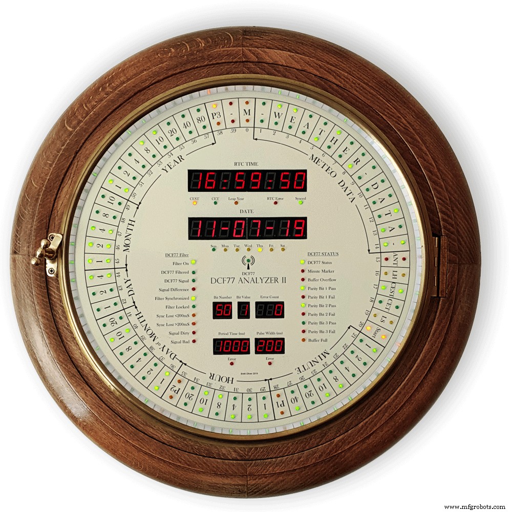
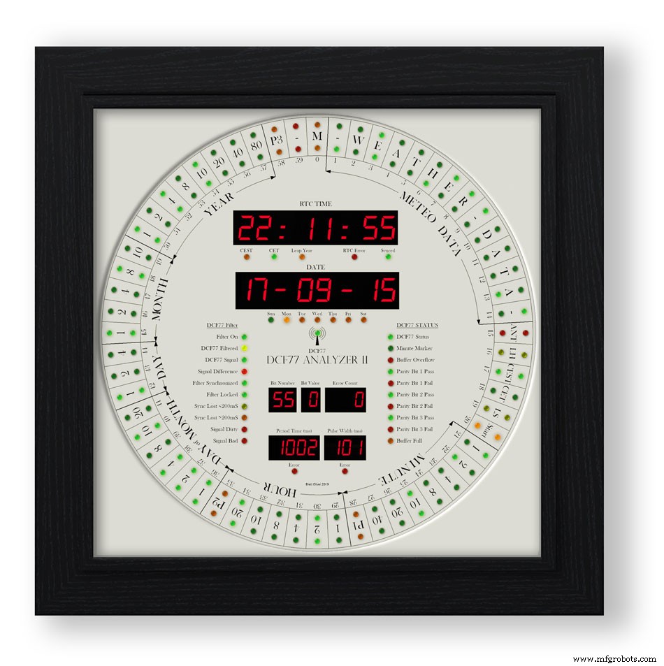
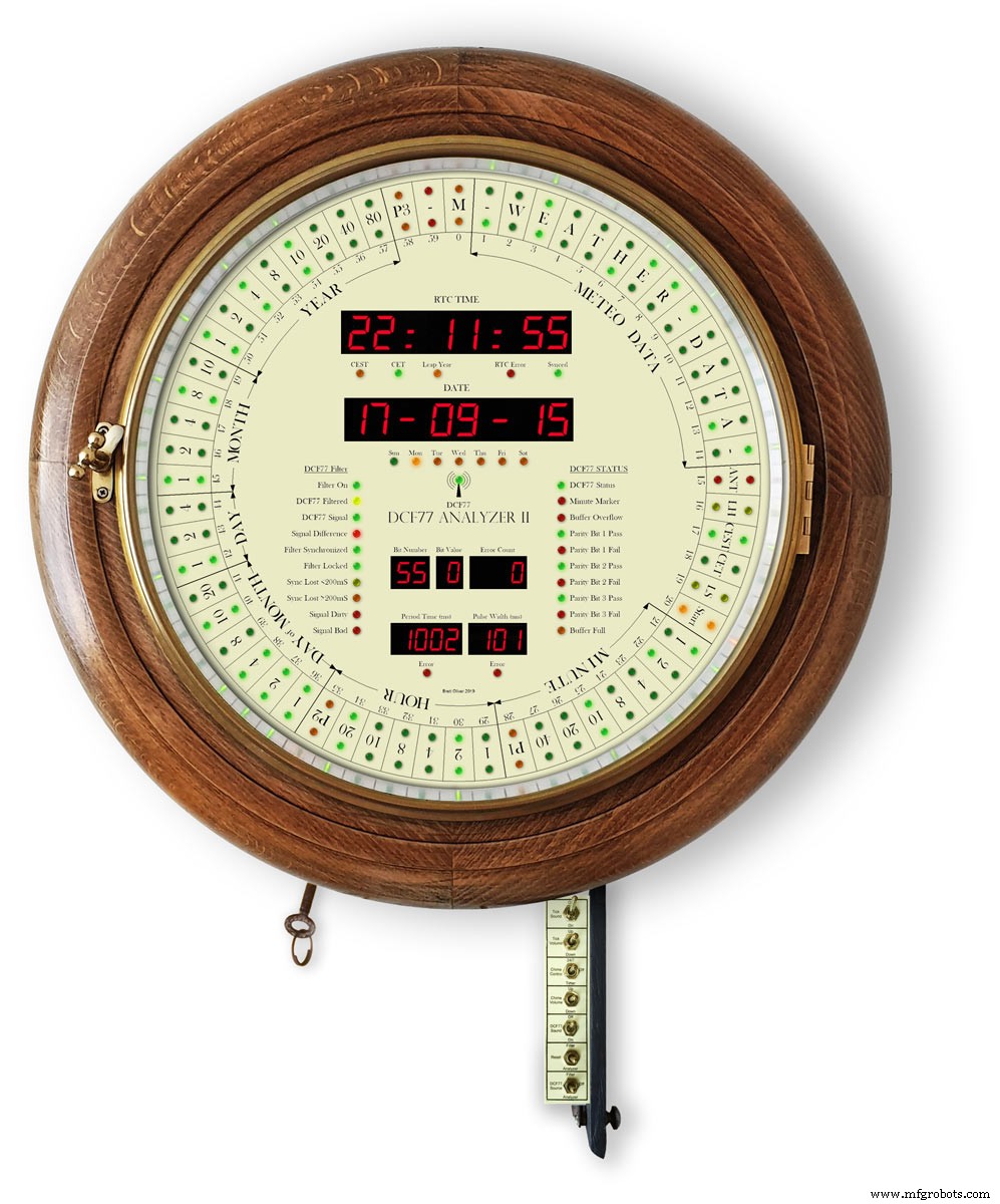
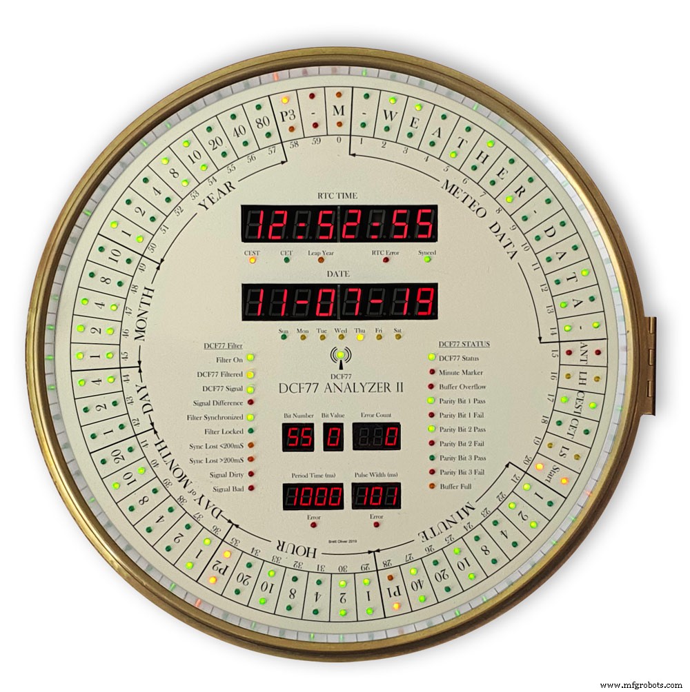
Diese Uhr zeigt den DCF77-Zeitcode auf 2 Ringen mit 60 LEDs auf einem großen Zifferblatt mit einem Durchmesser von 12" (305 mm) an. Der innere Ring zeigt den Live-Zeitcode für die nächste Minute beim Empfang und der äußere Ring zeigt die aktuelle Uhrzeit an wie die vorherige Minute wurde fehlerfrei empfangen.
Weitere 24 LEDs zeigen Decoderstatus und Zeitinfos an. Dekodierte Zeit und Datum werden auf 2 großen 8-stelligen 7-Segment-Anzeigen angezeigt, während DCF77-Impulszeiten und Bitinformationen auf weiteren 2 kleineren 8-stelligen 7-Segment-Anzeigen angezeigt werden.
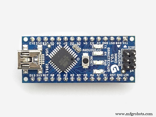
Die Uhr verwendet 2 x Atmega 328-Mikroprozessoren (Arduino Uno), 1 zur Steuerung des DCF77-Analyzers und 1 zur Steuerung eines Udo-Klein-Superfilters. Der Superfilter ermöglicht eine fortschrittliche DCF77-Signalverarbeitung und auch die Abstimmung des Arduino-Quarzkristalls. Der Filter ist umschaltbar und verfügt über 10 Status-LEDs zur Anzeige des Signalempfangszustands und der Ausgabequalität. Die Uhr schlägt auch die Stunden, Viertelstunden und Sekunden durch 2 von JQ6500 Soundmodulen.
Der Großteil der Elektronik ist auf der Rückseite des Zifferblatts montiert, sodass die Uhr an viele verschiedene Gehäuseformen angepasst werden kann.
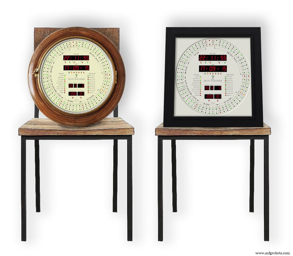
Ich habe Designs für Uhrengehäuse im Retro- und modernen Stil enthalten. das retro-design ist in ein altes zifferblattuhrengehäuse eingepasst, während das moderne design in einen schwarzen bilderrahmen passt.
Schritt 1:Gutschrift
Diese Uhr basiert auf der DCF77 Analyzer Clock von Erik de Ruiter und ist eine aktualisierte Version meiner Mk1 DCF77 Analyzer Clock.
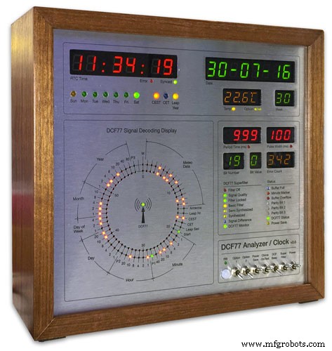
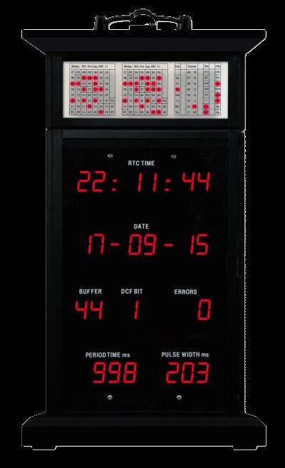
über der DCF77-Analysatoruhr von Erik de Ruiter unter meiner MK1 DCF77-Analysatoruhr.
Erik hat alle Details seiner Uhr auf GitHub bereitgestellt
Unterschiede zwischen Erics Uhr und meiner Uhr
Obwohl ich auf Erics Uhr basiert, habe ich ein paar Änderungen an der Hardware vorgenommen. Bitte kombinieren Sie die Option, die Ihren Anforderungen entspricht, aber stellen Sie sicher, dass Sie den Code entsprechend ändern.
Ich verwende zwei maßgeschneiderte Arduino UNo's auf dem Veroboard anstelle eines Uno und eines Mega.
Ich verwende durchweg billige 7-Segment-Anzeigen und Dot-Matrix-Module aus China und habe den Code entsprechend geändert. Sehen Sie sich den Abschnitt zu Anzeigefehlern an, da sie nach der Ausführung dieser Mods wirklich gut funktionieren.
Ich verwende 2x JQ6500-Module anstelle des Adafruit-Soundboards. Da eines meiner Boards softwaregesteuert ist, müssen einige Softwareänderungen und eine weitere Bibliothek geladen werden.
Da ich ein Arduino Uno anstelle eines Arduino Mega habe, habe ich nicht alle Ersatzpins, um die Decoder-LEDs anzusteuern, daher verwende ich stattdessen ein 3. Punktmatrixmodul.
Ich habe den Superfilter von Udo Klein modifiziert, indem ich zusätzliche Staus-LEDs hinzugefügt habe. Die Helligkeit dieser LEDs wird vom DCF77-Decoder Uno über 2 Transistoren PWM gesteuert, nicht vom Super Filter Uno.
Passend zur DCF77-Decoder-Testfunktion ist dem Superfilter auch eine LED-Testfunktion hinzugefügt worden.
Ich verwende nur 3-mm-LEDs und habe LEDs mit angepasster Helligkeit ausgewählt, um zu versuchen, die Helligkeit gleichmäßig zu halten.
Ich habe in der Software 4 separate Intensitätsstufen hinzugefügt, sodass die Ring-/Status-LEDs, die großen 7-Segment-Anzeigen, die kleinen 7-Segment-Anzeigen und die Superfilter-LEDs alle benutzerdefinierte Helligkeitsstufen haben, abhängig von den Messwerten des einzelnen LDR.
Ich habe keine Temperatur- oder Wochennummernanzeige auf meiner Uhr und habe den Code entsprechend geändert.
Ich habe meinem Superfilter zusätzliche Monitor-LEDs hinzugefügt, sodass es auf meiner Uhr nur eine Option für synthetisierte und nicht synthetisierte Ausgabe gibt. Dies ist keine Option, um den Modus gemäß Eriks Uhr zu wechseln.
Der DCF77-Sound meiner Uhr wurde modifiziert, um den Unterschied zwischen den eingehenden 0s und 1s zu betonen. Wenn die Uhr eine 1 erkennt, spielt sie nur einen etwas längeren Ton als 200 ms ab.
Schritt 2:Video
Das Video zeigt die Uhr, die mit dem Tick-Ton läuft und auch die Uhr, die die ganze Viertelstunde und die volle Stunde schlägt.
Es zeigt auch das Zifferblatt-Layout und Informationen zum Ablesen der Displays.
Video 2
Video zum Einschalten, Displaytest und Zeit-/Datumsdecodierung
Video 3
Video, das zeigt, wie der Udo Klein Super-Filter auf dieser Uhr funktioniert
Video 4
Das Video zeigt die Bilderrahmenuhr, die mit dem Tick-Ton läuft und auch die Uhr, die die volle Viertelstunde und die volle Stunde schlägt.
Es zeigt auch das Zifferblatt-Layout und Informationen zum Ablesen der Displays.
Video 5
Dieses kurze Video zeigt meine DCF77-Analysatoruhr, die das DCF77-Signal anzeigt und decodiert. Alle Töne sind außer dem DCF77-Live-Signal.
Schritt 3:Steuerung
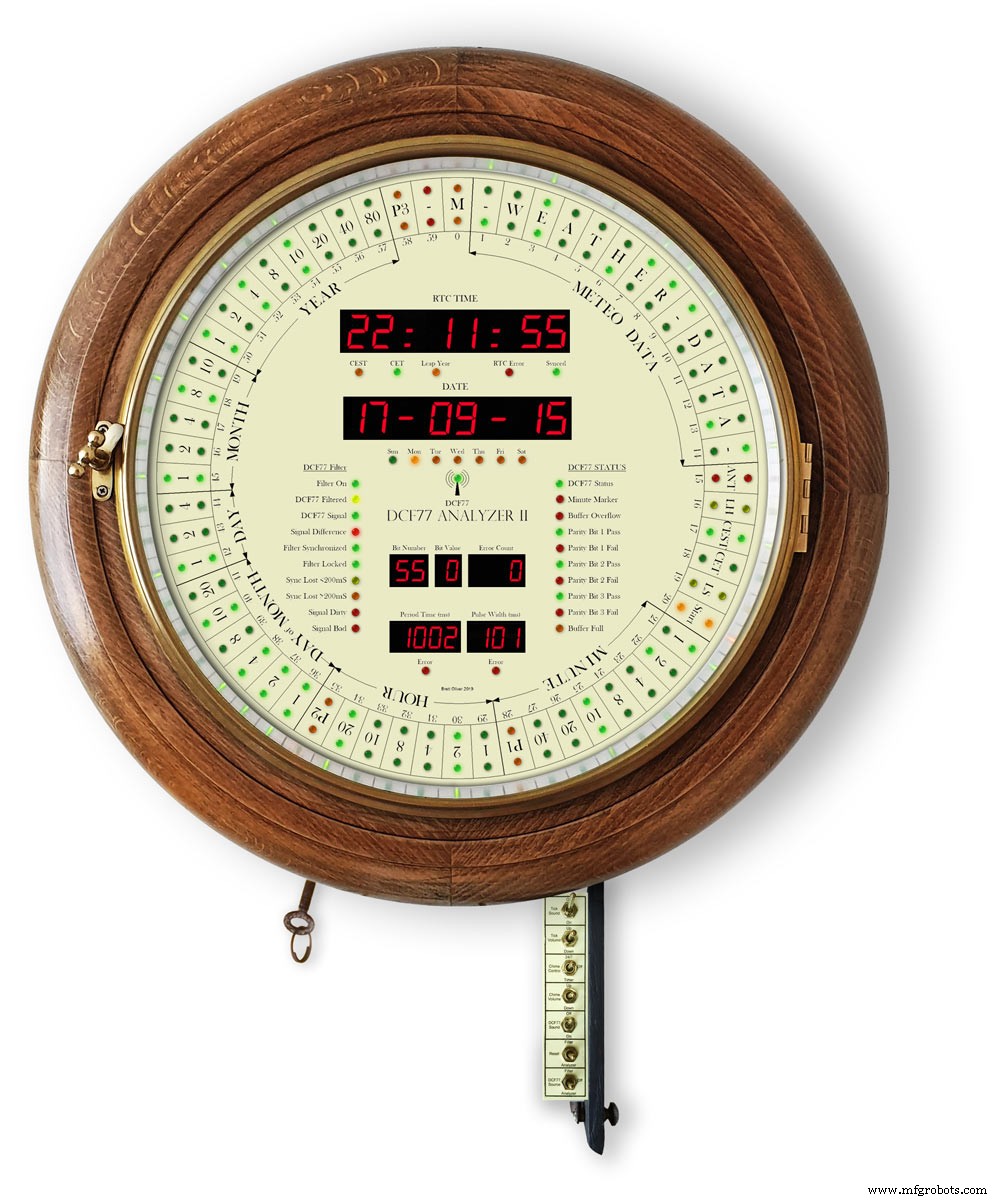
Die Uhr wird über 7 Schalter gesteuert, die auf einer Metallstange montiert sind. Die Schalter sind an der Innenseite einer Flügeltür angebracht, die für den Zugriff unter die Uhr heruntergeklappt werden kann.
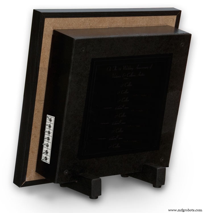
Bei der Bilderrahmenversion sind die Schalter in einer Aussparung an der Seite der Uhr angebracht.

Schalter steuern folgendes
Ton an/aus ankreuzen
Tick Lautstärke
Glockenspiel rund um die Uhr oder Timer
Glockenlautstärke
DCF77-Ton Ein/Aus
Superfilter oder Analysator zurücksetzen
DCF77-Quelle von Filter, Aus oder Analysator
Schalterfunktionen
Tick-Ton
Schaltet den Tick-Tack-Sound ein und aus (unterbricht die Stromversorgung des JQ6500-Moduls)
Häkchen Lautstärke nicht sperrend
Stellt die Tick-Tack-Lautstärke auf und ab (Tick-Sound-Schalter muss eingeschaltet sein)
Klingelsteuerung
Aus-Glocken sind ausgeschaltet
Rund-um-die-Uhr-Glocken sind rund um die Uhr aktiv
Timer-Gongs sind nur zu bestimmten Tageszeiten aktiviert, z.B. nachts aus
Klanglautstärke nicht sperrend
Up erhöht die Lautstärke
Leiser verringert die Lautstärke
Nach jedem Tastendruck ertönt ein Testton, damit Sie die neue Lautstärkeeinstellung hören können
DCF77-Sound
On spielt den DCF77-Sound ab, der als Piepton über den piezoelektrischen Sounder empfangen wird.
0 ist 100 ms und 1 wird als 500 ms-Piepton abgespielt, um die empfangenen 0 &1er besser unterscheiden zu können.
Aus der DCF77-Piepton ist Aus
Nicht sperrende Sperre zurücksetzen
Filter setzt den DCF77 Super Filter zurück und synchronisiert ihn erneut mit dem DCF77 Signal
Der Analysator setzt den DCF77-Analyzer zurück, beginnend mit einem Anzeigetest, falls aktiviert, und dann einer Neusynchronisierung der Uhr. Die RTC-Zeit wird ab der in der Echtzeituhr gespeicherten Zeit angezeigt
DCF77-Quelle
Off trennt das DCF77-Signal von der Uhr
Analysator wird das DCF77-Signal ohne Filterung direkt der Uhr zugeführt
Filter Das DCF77-Signal wird vom Superfilter genommen und wenn der Superfilter synchronisiert ist, wird dieses Signal zum korrekten fehlerfreien Signal synthetisiert
Schritt 4:Schaltpläne
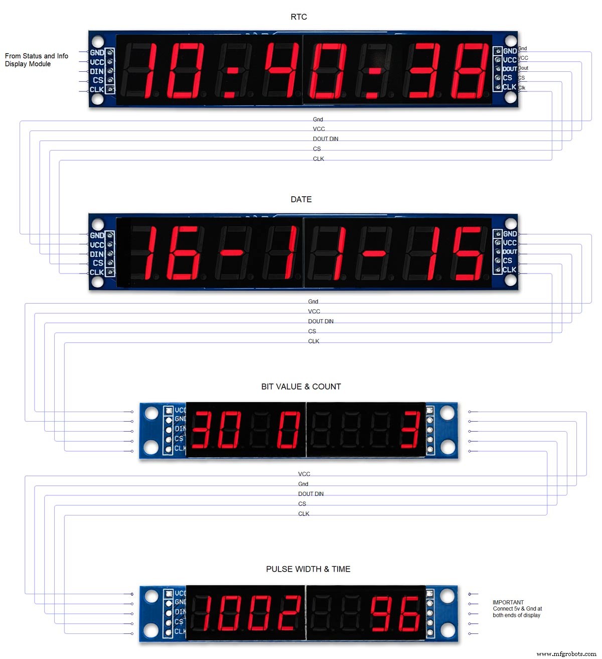
Es gibt 3 Schaltpläne für diese Uhr. Das Mainboard, die Dot-Matrix-Module und die 7-Segment-Anzeigemodule.
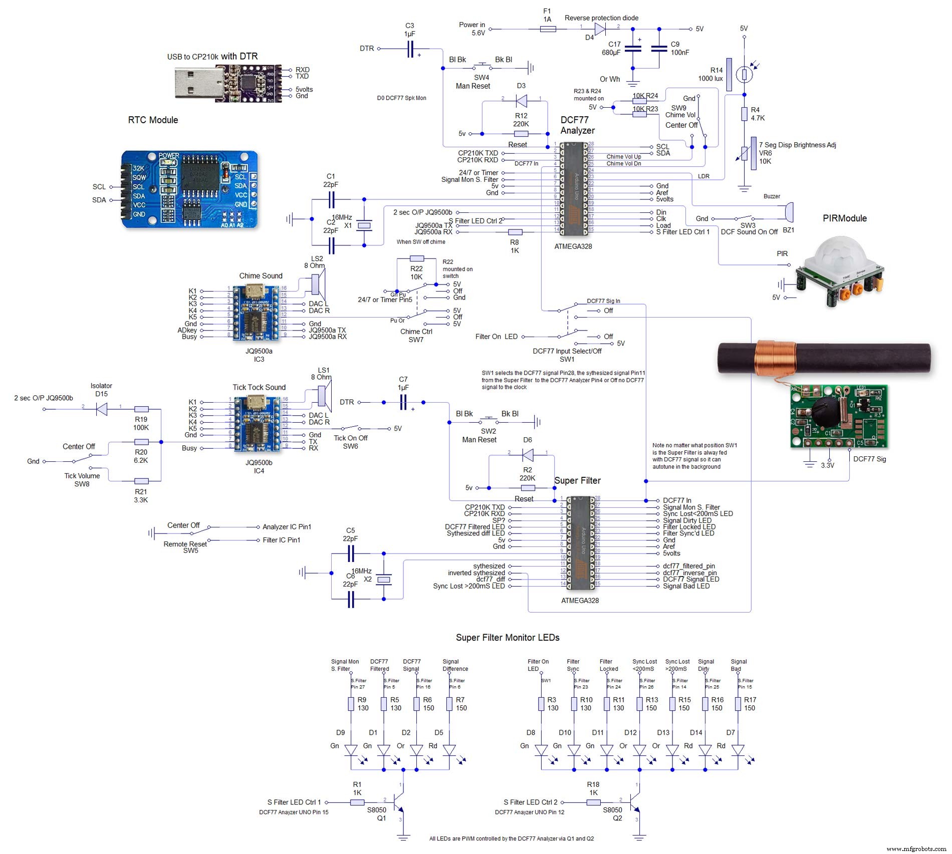
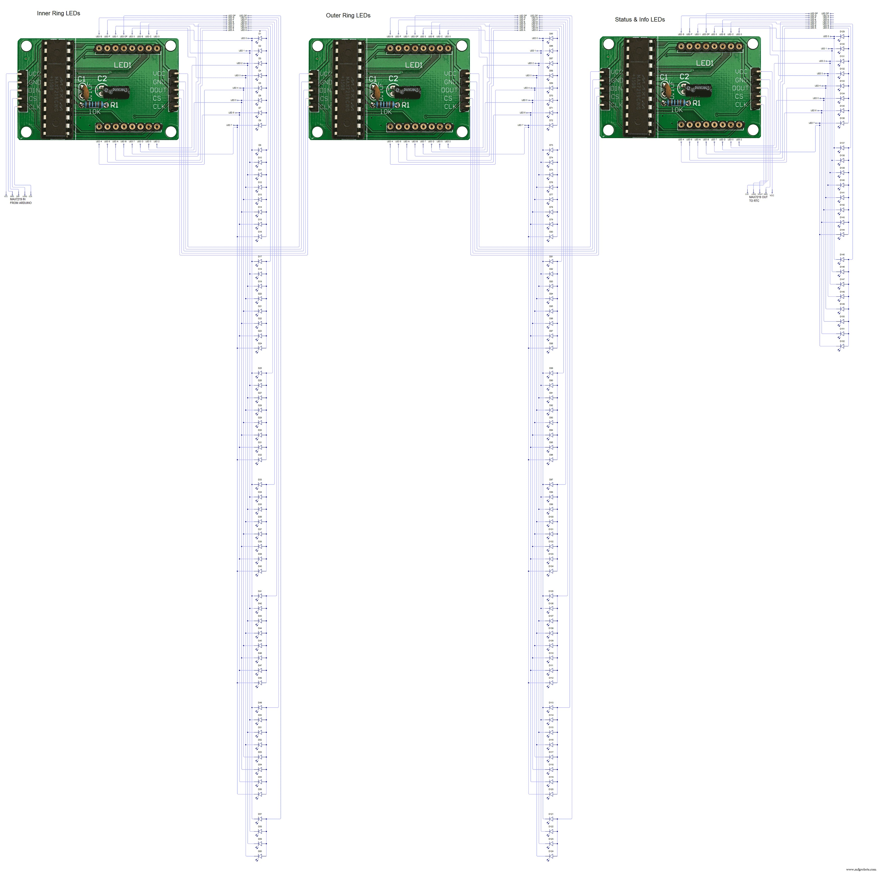
Die 2. ist sehr groß und kann hier in voller Größe 4000x4000 schematisch angezeigt werden. Ich habe es so ausgelegt, dass es einfach zu verkabeln ist.

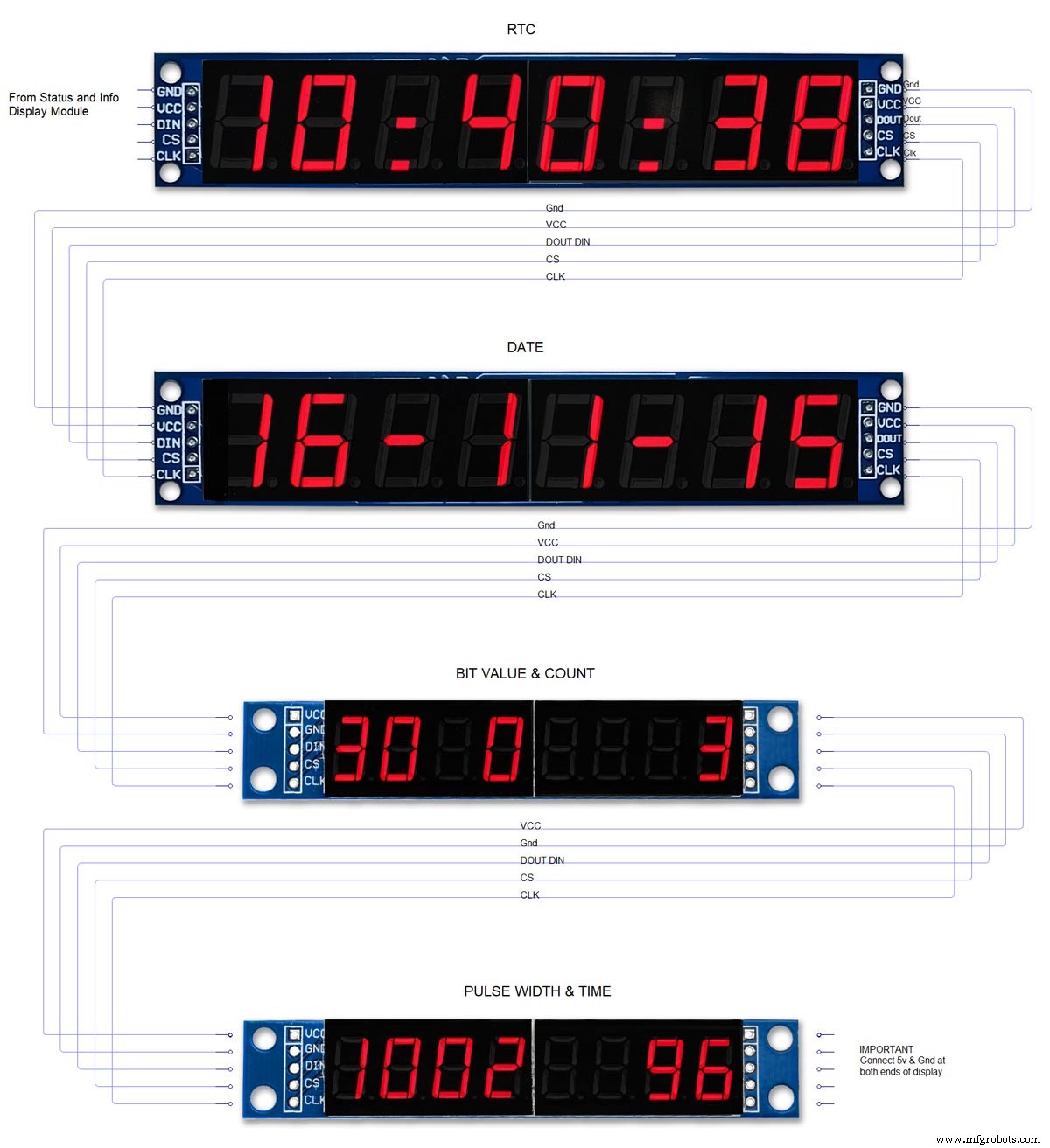
Schritt 5:Atmega-Pin-Verbindungen
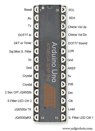
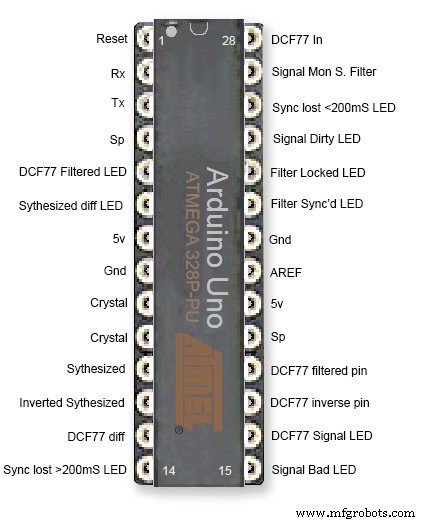
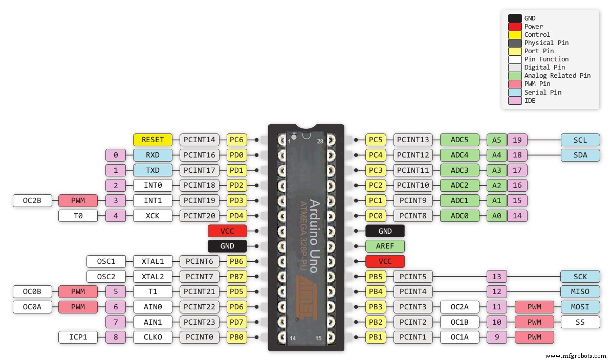
Diese Uhr verwendet 2 Atmega 328 ICs auf benutzerdefinierten Vero-Boards. Für den Analysator-Teil der Uhr kann ein Standard-UNO verwendet werden, aber für den Superfilter-Teil der Uhr muss ein UNO mit einem Quarzkristall anstelle eines Resonators verwendet werden. Sehen Sie hier, wie Sie einem Arduino UNO einen Quarzkristall hinzufügen http://www.brettoliver.org.uk/Master_Clock_MK2/Master_Clock_MK2.htm#Mod
Schritt 6:Vero-Board-Layouts
Viele der Module für dieses Projekt sind vorgefertigt und müssen nur eingesteckt werden, aber die Hauptplatine für die Arduinos, die Soundmodule und die 3. LED-Matrix müssen auf der Vero-Platine gebaut werden.
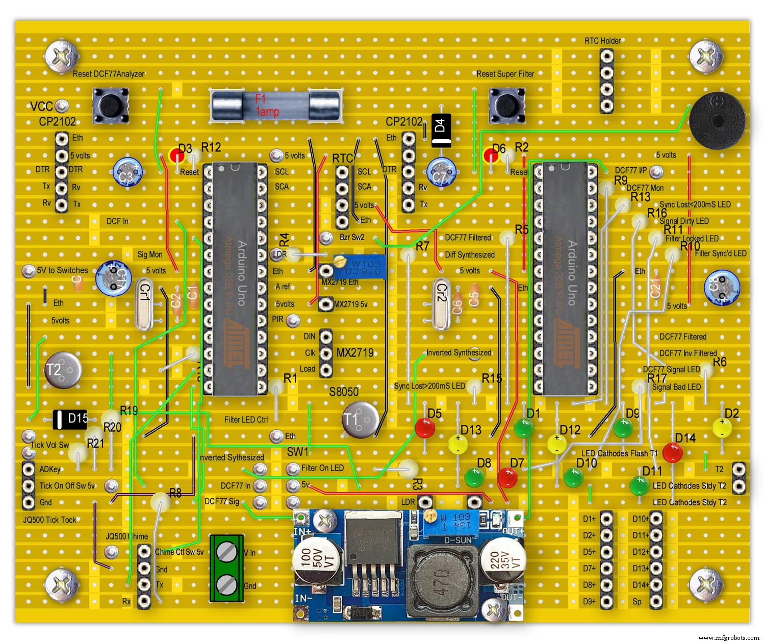
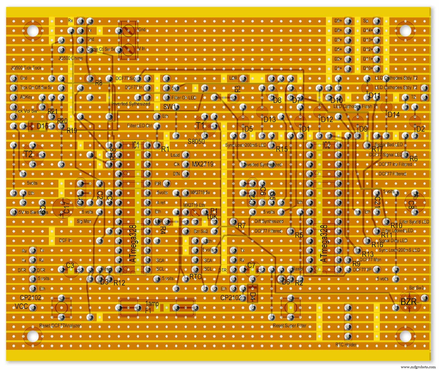
Die LEDs sind nur zu Referenzzwecken auf der Hauptplatine montiert dargestellt.
Die gesamte Verkabelung von der Hauptplatine zu anderen Platinen erfolgt über PCB-Header-Steckverbinder. Die Verbindungen von der Hauptplatine zur Schalttafel sind direkt verdrahtet. Dadurch können die Hauptplatine und die Schalttafel zu Wartungszwecken entfernt werden.
Beachten Sie, dass diese als Arduino UNOs konfiguriert sind und während vorgefertigte Unos oder Nanos verwendet werden könnten, muss der Super Filter Arduino einen Quarzkristall haben, keinen Resonator für Genauigkeit siehe Atmega Pin-Anschlüsse oben.
Siehe die Informationen auf meiner Master Clock-Site Arduino-Quarzkristallmodifikation
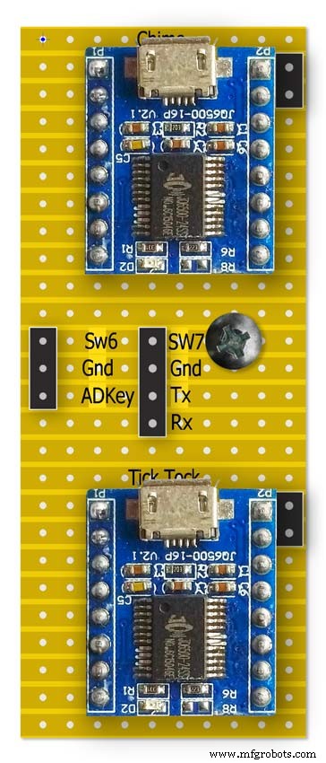
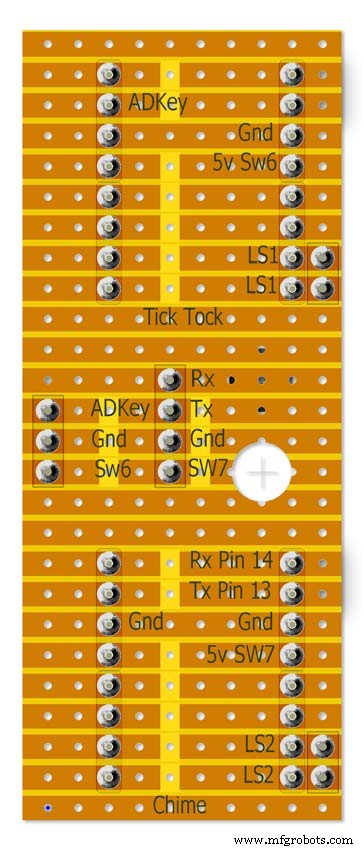
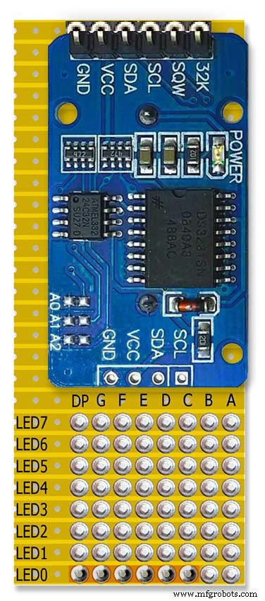
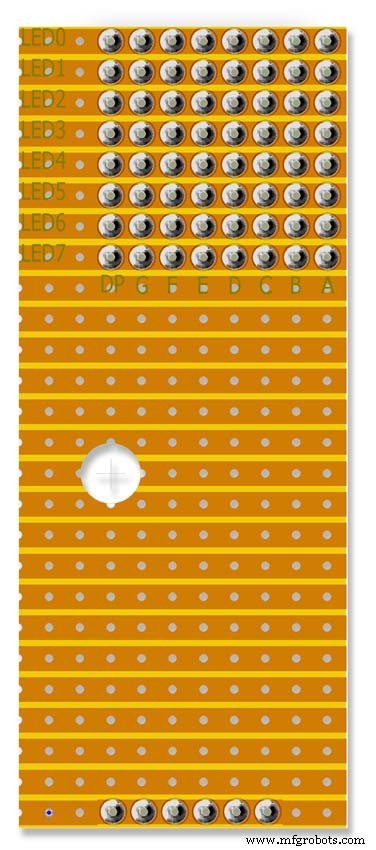
Hinweis Die RTC wird hier montiert, aber nur über das Header-Kabel verbunden.
Schritt 7:Vorgefertigte Module
Vorgefertigte Platine und Module
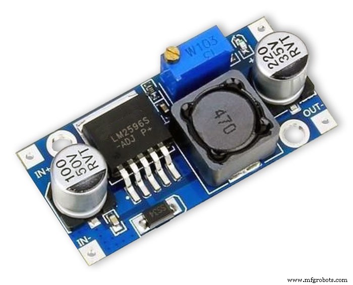
Das LM2596-Reglermodul senkt die Spannung auf 5 V. Dieser wird durch den 10K voreingestellten Widerstand am Modul eingestellt und nach der Reverses-Schutzdiode D4 gemessen. Passen Sie dies an, bevor Sie die Arduinos zum Board hinzufügen.
Die Uhr verbraucht maximal etwa 450 mA mit LEDs bei voller Helligkeit und fällt bei ausgeschalteten Displays auf etwa 80 mA ab.
Mit einem 1000-mA-DC-Netzteil von 7 -12 Volt sollten Sie auf der sicheren Seite sein (das LM2596-Reglermodul steuert die Spannung)
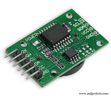
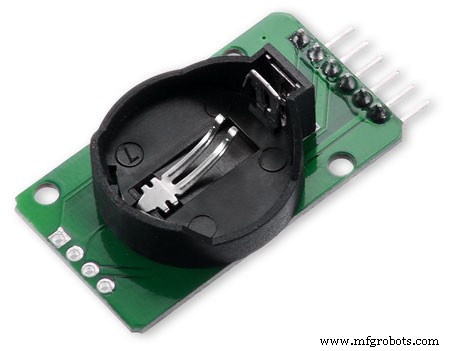
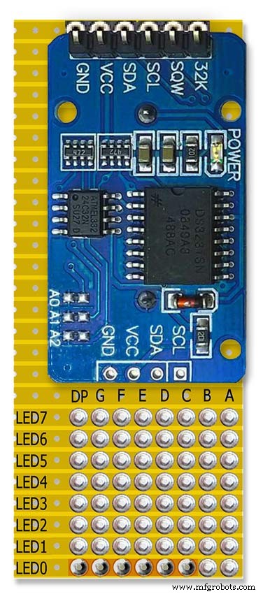
RTC DS3231 I2CDieses Modul speichert die Zeit aus dem dekodierten DCF77-Signal. Die eingebaute Uhr verfügt über eine Temperaturkompensation und eine Batterie-Backup bei Stromausfall. Beachten Sie, dass das RTC-Modul so modifiziert wurde, dass es nicht wiederaufladbare Batterien aufnehmen kann.
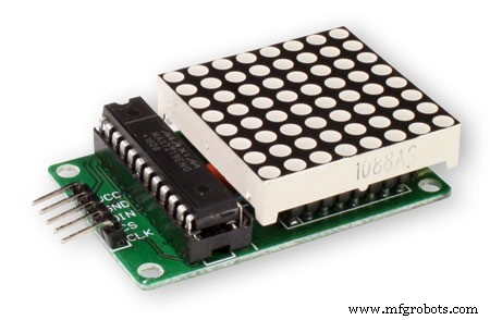
MAX2719 Dot-Matrix-ModulDiese Module steuern die inneren und äußeren LED-Ringe (2 Module) und das dritte Modul steuert alle anderen LEDs außer den Superfilter-LEDs. Die LED-Matrix wird entfernt und ein PCB-Header angelötet.
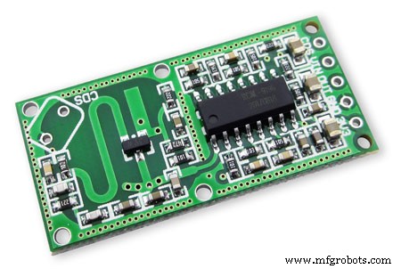
RCWL 0516 Doppler-Radarsensor MikrowelleUm die Uhranzeigen nur einzuschalten, wenn der Raum besetzt ist, verwende ich Bewegungserkennung. Sie haben die Wahl zwischen dem RCWL 0516 unten, das Bewegungen hinter Glas erkennt oder dem PIR-Modul unten.
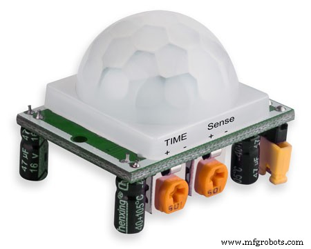
PIR-Modul InfrarotDas PIR-Modul kann anstelle des obigen Doppler-Radarsensors verwendet werden. Der Nachteil dieses Geräts ist, dass es nicht hinter Glas oder Plexiglas usw. verwendet werden kann.

Max2719 7-Segment-Anzeige 0,56" Dies ist die größere 0,56"-Version, die für die Zeit- und Datumsanzeige verwendet wird. Ich hatte schon eine Menge davon, aber es gibt ähnliche Module auf Tindie. Stellen Sie nur sicher, dass Sie die größeren 0,56-Zoll-Displays erhalten. Beachten Sie, dass möglicherweise eine kleine Änderung erforderlich ist, um Anzeigefehler an diesen Modulen zu vermeiden. Siehe den Änderungsschritt des MAX2719.

Max2719 7-Segment-Anzeige 0,39" Dies ist die kleinere 0,39"-Version, die für die Bit-, Fehler- und Impulsanzeigen verwendet wird. Sie sind überall bei eBay und Amazon erhältlich. Stellen Sie nur sicher, dass Sie die Module mit nicht gelöteten Header-Pins oder die Platinen mit den Pins, die an der Rückseite des Moduls gelötet sind, erhalten. Beachten Sie, dass möglicherweise eine kleine Änderung erforderlich ist, um Anzeigefehler auf diesen Modulen zu vermeiden. Siehe den MAX2719-Modifikationsschritt.
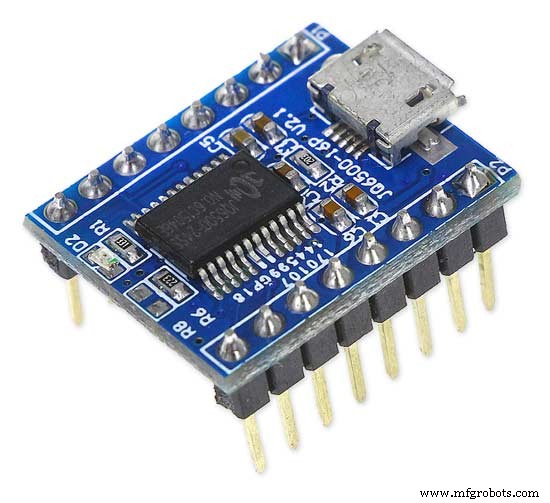
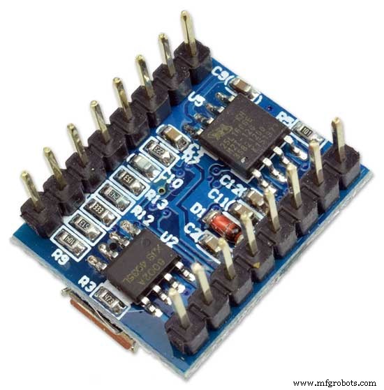
JQ6500 16p ModuleEines dieser Module wird verwendet, um den tickenden Sound und das andere die Viertel- und Stundenglocken zu spielen. Mit den im Projekt enthaltenen Sounddateien sollte man mit dem günstigsten 16p-Modul mit 2M Speicher auskommen. Die Module treiben jeweils einen einzelnen 3W 8Ω Lautsprecher an. Sounds werden von Ihrem PC (nicht MAC) über USB mit einem einfachen Programm geladen.
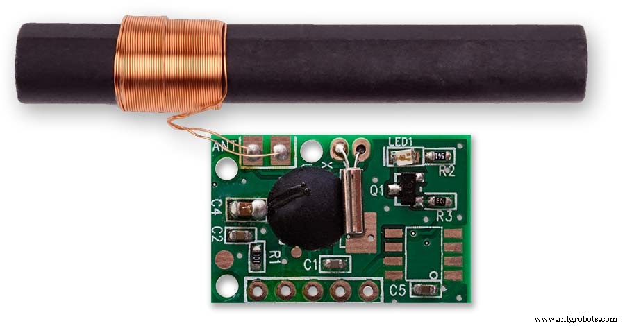
DCF77-Empfänger
Mein DCF77-Empfängermodul von http://www.pvelectronics.co.uk
Diese Artikel scheinen nicht mehr verfügbar zu sein, aber versuchen Sie es mit Amazon
PV Electronics DCF77 Empfängermodulanschlüsse Anschlüsse von links nach rechts
1.VDD 2.TCON 3.PON 4.GND 5.NC
Liefert die Ausgabe in einem invertierten Format (die Ausgabe ist niedrig und geht einmal pro Sekunde hoch).
Standby-Modus mit geringem Stromverbrauch - PON mit Vdd verbinden.
Verbinden Sie PON mit GND für den normalen Betrieb.
Halten Sie den Empfänger von Fernsehern, Monitoren oder anderen elektrischen Störungen fern und stellen Sie sicher, dass er auf den DFC77-Sender gerichtet ist.
Komponenten
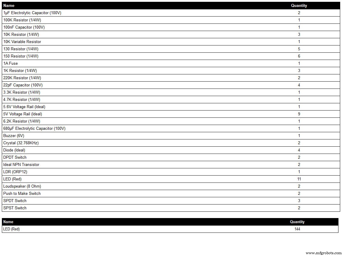
Liste der Komponenten, die aus meinem Schaltplan-Zeichenprogramm LiveWire generiert wird, so dass möglicherweise nicht alle Details angezeigt werden, wenn sich die Komponente nicht in der Programmbibliothek befindet, z. B. einige der Schalter. Überprüfen Sie den Schaltplan für Details oder kontaktieren Sie mich.
Die LED-Farbe kann nach Bedarf gewählt werden, aber siehe die LED-Sektion für die tatsächlich verwendeten LEDs.
Schritt 8:Verdrahtungsreihenfolge
Bei etwa 400 ungeraden anzuschließenden Drähten erfordert die Verdrahtung viel Planung, um die Verdrahtungsstrecken in die Lücken zwischen den Modulen zu passen.
Bauen Sie bei Bedarf modifizieren und befestigen Sie alle Platinen an der Rückseite des Zifferblatts, damit die Kabelbaumverläufe sichtbar sind.
Die Punktmatrixplatinen werden entfernt und von der Uhr entfernt verdrahtet.
Verdrahten Sie die Superfilter-LEDs und passen Sie sie in das Zifferblatt ein.
Verdrahten Sie die DCF77-Status-LEDs und passen Sie sie in das Zifferblatt ein.
Die Superfilter- und DCF77-Status-LEDs sind über Header-Kabel mit der Hauptplatine verbunden. Verdrahten Sie alle LEDs des Dot-Matrix-Moduls 3 und passen Sie sie in das Zifferblatt ein.
Verdrahten Sie das Punktmatrixmodul 3 mit der kleinen Breakout-Vero-Platine und verdrahten Sie dann die LEDs für dieses Modul, die im obigen Schritt montiert wurden.
Verdrahten Sie den äußeren LED-Ring und passen Sie ihn dann in das Zifferblatt ein.
Verdrahten Sie das Dot-Matrix-Display des äußeren Rings und lassen Sie die Drahtenden lang genug, um an den LEDs des äußeren Rings zu enden.
Bringen Sie die Dot-Matrix-Anzeige des äußeren Rings wieder an und schließen Sie den Kabelbaum an den LEDs des äußeren Rings an.
Verdrahten Sie den inneren LED-Ring und passen Sie ihn dann in das Zifferblatt ein.
Verdrahten Sie das Punktmatrix-Display des inneren Rings und lassen Sie die Drahtenden lang genug, um an den LEDs des inneren Rings zu enden.
Bringen Sie die Dot-Matrix-Anzeige des inneren Rings wieder an und schließen Sie den Kabelbaum an den LEDs des inneren Rings an.
Verdrahten Sie alle LEDs des Dot-Matrix-Moduls 3 und passen Sie sie in das Zifferblatt ein.
Verdrahten Sie das Punktmatrixmodul 3 mit der kleinen Breakout-Vero-Platine und verdrahten Sie dann die LEDs für dieses Modul, die im obigen Schritt montiert wurden.
Bauen Sie Header-Kabel und verbinden Sie sie mit allen Boards.
Montieren Sie das Haupt-Vero-Board und verkabeln Sie es dann mit der Schalttafel. Der LDR wird durch die aufklappbare Holztür montiert, an der die Schalttafel befestigt ist, so dass diese gleichzeitig verkabelt wird.
Lautsprecher einbauen und mit den JQ6500 Soundmodulen an das Vero Board anschließen.
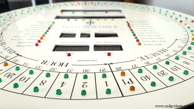
Wenn Sie die Löcher in der richtigen Größe in das Zifferblatt gebohrt haben, werden alle LEDs ohne Klebstoff einrasten. Stellen Sie sicher, dass die Innenkanten der LED-Löcher in der Lackierphase mit Farbe/Lack beschichtet sind, um die Reibungspassung zu unterstützen.
Schritt 9:Verdrahtung des Max2719 Dot-Matrix-Moduls
Bevor Drähte an die MAX 2917 Matrixmodule angeschlossen werden können, müssen sie modifiziert werden.
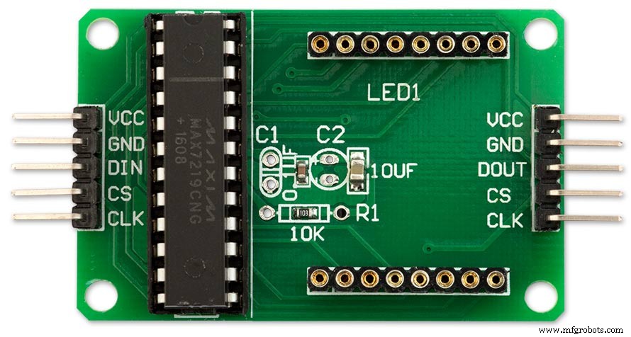
Entfernen Sie die Dot-Matrix-LEDs, da diese nicht benötigt werden.
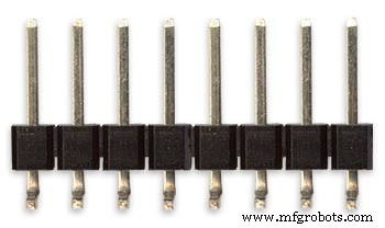
Zwei Sätze von 8 90°-Pin-Anschlüssen werden an die Unterkante des bestehenden LED-Matrix-Anschlusses angelötet.
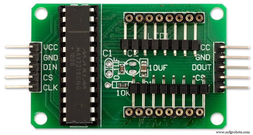
Modifiziertes MAX7219-Modul mit 90°-Pin-Anschlüssen, die an der Unterseite der alten LED-Matrix-Anschlüsse angelötet sind. Die Drähte werden von diesen Punkten zur LED-Matrix auf der Hauptplatine entfernt.

Seitenansicht, die die Pins zeigt, die an die Seite der alten LED-Matrix-Steckerstifte direkt über der Platine gelötet sind.
Schritt 10:Verdrahtung Aufbau einer Verdrahtungslehre
Die Schablone hält die LEDs mit dem richtigen Abstand an Ort und Stelle, was eine einfache Verdrahtung von der Uhr entfernt ermöglicht.
Aufbau einer Verdrahtungslehre für die LEDs
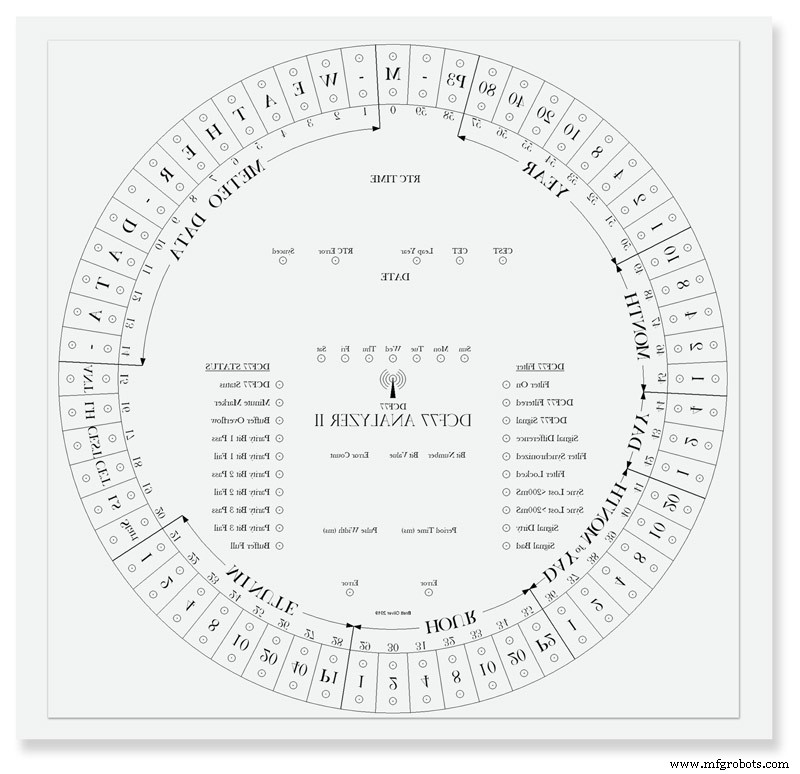
Drucken Sie das Zifferblatt auf einem Blatt Papier aus. Drucken Sie rückwärts oder legen Sie das Papier von hinten nach vorne, da Sie von der Rückseite der Uhr arbeiten. Legen Sie das Blatt auf ein altes Stück Holz oder Melamin. Alle LED-Zentren ankörnen und mit einem 3mm Bohrer bohren. Das Loch sollte reibschlüssig auf den LEDs sitzen, um eine einfache Verdrahtung zu gewährleisten. LEDs unterscheiden sich im Durchmesser, machen Sie also zuerst ein paar Testlöcher, um die richtige Größe für Ihre LEDs zu erhalten.
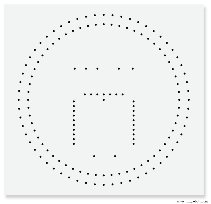
Fertige Verdrahtungslehre.
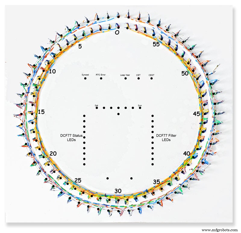
Fertige innere und äußere LED-Ringe an der Vorrichtung. Es kann praktisch sein, die LED-Nummern und andere Informationen auf die Schablone zu schreiben, um sicherzustellen, dass Sie die richtigen LEDs verdrahten, da die LEDs an der Rückseite des Zifferblatts angebracht sind und gegen den Uhrzeigersinn aufgedreht werden.
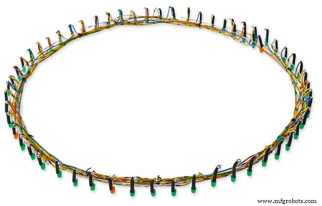
Ring aus LEDs aus der Schablone entfernt, bereit zum Einsetzen in das Zifferblatt.
Schritt 11:Verdrahtung des inneren und äußeren LED-Rings
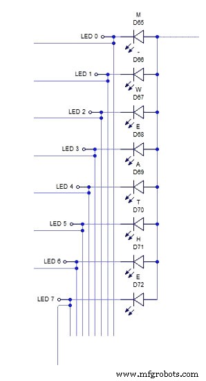
Das obige schematische Diagramm zeigt die Verdrahtung für einen Abschnitt von 8 LEDs des äußeren LED-Rings.

Schieben Sie zuerst die acht LEDs in die Löcher in der Schablone. Biegen Sie alle Anoden so, dass sie gemäß dem Schaltplan miteinander verbunden sind, und löten Sie sie an. An die acht angeschlossenen Anoden des LED-Matrix-Moduls wird später ein Draht angeschlossen. Passen Sie ein kleines Stück Isolierhülle über die Kathoden und biegen Sie diese Beine um 15 mm von der LED. Schneiden Sie etwa 5 mm von der Biegung ab und löten Sie ein kurzes Stück Draht, das lang genug ist, um die nächste Charge von acht LEDs zu erreichen. Siehe Bild2.
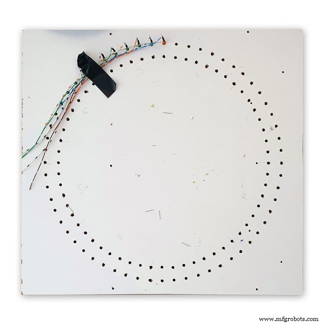
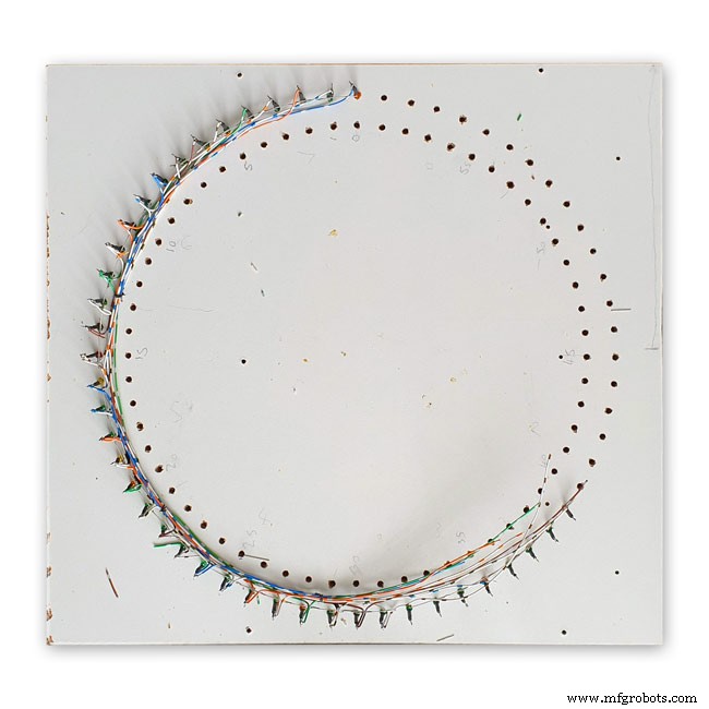
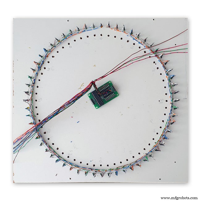
Bild 1 Dies zeigt einen vollständigen Abschnitt von 8 LEDs, die an der Vorrichtung verdrahtet sind, wobei die Drähte zum nächsten Abschnitt von 8 LEDs führen.
Bild 2 Wiederholen Sie den obigen Vorgang in Chargen von acht LEDs.
Jede Charge von acht LEDs hat eine eigene separate Anodenverbindung zum Dot-Matrix-Modul. Insgesamt acht.
Bild 3 Äußere Ring-LEDs zusammen mit den 16 Drähten, die mit dem Punktmatrix-Display verbunden sind.
Anschließend werden die LEDs in die Löcher im Zifferblatt geschoben und das Matrixmodul wieder am Zifferblatt befestigt. Sobald die 16 Drähte des Dot-Matrix-Moduls an Ort und Stelle sind, werden sie mit den äußeren Ring-LEDs verbunden. Dieser Vorgang wird für den inneren LED-Ring wiederholt.
Die 16 Drähte des Dot-Matrix-Moduls können über die 8 Sätze von 8 LED-Sektionen angeschlossen werden. Beachten Sie, dass der 8. Satz nur 4 LEDs hat. Den 4000x4000-Schema in voller Größe finden Sie hier.
Die LEDs
Ich habe High Efficiency LEDs der Vishay TLH44-Serie in einem Ø 3 mm getönten Diffuse-Paket verwendet
BESCHREIBUNG Die Serie TLH.44.. wurde für Standardanwendungen wie allgemeine Anzeige- und Beleuchtungszwecke entwickelt. Es ist in einem 3 mm getönten, diffusen Kunststoffgehäuse untergebracht. Der weite Betrachtungswinkel dieser Geräte bietet einen hohen Ein-Aus-Kontrast.
Es werden mehrere Auswahltypen mit unterschiedlichen Lichtstärken angeboten. Alle LEDs sind in Lichtstärkegruppen eingeteilt. Dadurch können Benutzer LEDs mit einheitlichem Erscheinungsbild zusammenbauen.
EIGENSCHAFTEN
• Standardpaket Ø 3 mm (T-1)
• Kleine mechanische Toleranzen
• Geeignet für Gleichstrom und hohen Spitzenstrom
• Großer Betrachtungswinkel
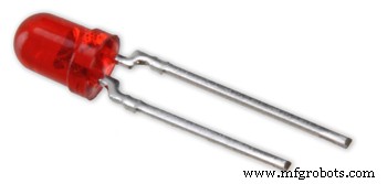
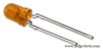

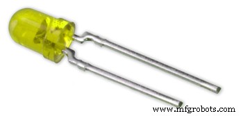
Bild 1-4 oben zeigt die LED-Farben, wobei das Bild unten die Tabelle mit den tatsächlichen Teilenummern zeigt.

12:3. Dot-Matrix-Modul verdrahten

Verdrahtung des 3. Dot-Matrix-Moduls
Dieses Modul hat nur 24 von 64 angeschlossenen LEDs.
Die Wochentag-LEDs im 1. Abschnitt von 8 LEDs (nur 7 verbunden)
Die 2. von 8 LEDs sind CEST, CET Leap Yr, RTC Error, Synced, Error Period und Error Pulse Width (nur 7 verbunden)
Die dritte von 8 LEDs sind Buffer Full, Parity 3 to 1 pass and fail und Buffer Overflow (alle 8 LEDs verbunden)
Die 4. von 8 LEDs enthält nur 2 LEDs Minutenmarkierung und DCF77-Status
Ich hätte einfach 3 Sätze mit 8 LEDs verwenden können, aber die Verwendung von 4 Sätzen machte die Verkabelung einfacher.
Diese LEDs werden auf der Verdrahtungsschablone verdrahtet und dann mit einer kleinen Vero-Platine verbunden, wo sie mit den Matrixdrähten verbunden sind. Beachten Sie, dass dieses Board auch als Halterung für die RTC dient.
Schritt 13:Schalttafel verdrahten
Die Schalttafel schwenkt unter die Uhr, die an der Rückseite der Zugangstür befestigt ist. Die Verkabelung ist direkt auf die Hauptplatine gelötet und beinhaltet die Verkabelung für den LDR.

Schaltfeld
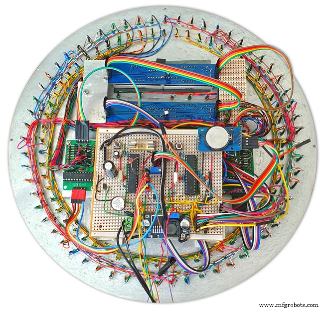
Schalttafelverkabelung im Gange
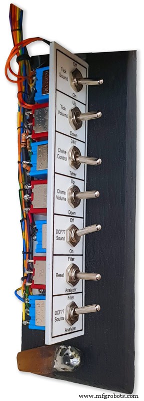
Schalttafel mit fertigem Kabelbaum, montiert an der Tür an der Unterseite der Uhr
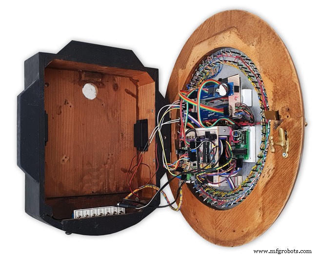
Komplette Verkabelung mit dem Kabelbaum für die Schalter, die sich von der Hauptplatine nach unten schlängeln. Die Schalttafel ist in das Uhrengehäuse eingeklappt dargestellt.
Schritt 14:Glocken- und Tick-Tock-Sounds auf dem JQ6500
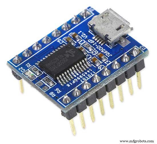
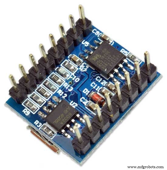
Diese Uhr verwendet 2 x JQ6500-Module, eines für den Tick-Tack-Sound und eines für die Viertel- und Stundenglocken. Der Tick-Tack-Sound ist hardwaregesteuert und die Glocken sind softwaregesteuert.
Klangkreis
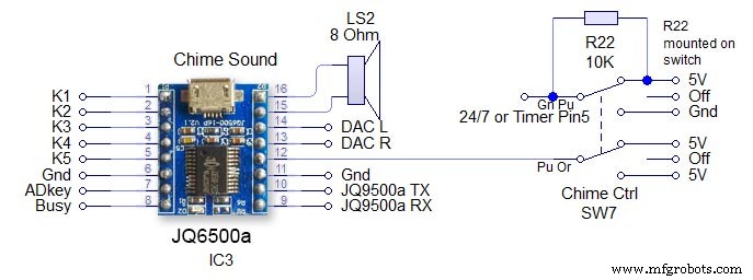
Schalter SW7 ist ein 3-Positionen-Verriegelungsschalter. Das Modul wird über die seriellen Hardware-Pins 13 &14 auf dem Arduino gesteuert. Beachten Sie den 1K-Widerstand im Empfangskreis. Siehe Hauptschaltplan. Aus - Die Stromversorgung des JQ9500 wird unterbrochen und der 24/7/Timer-Pin wird hoch gehalten, um zu verhindern, dass der Arduino-Pin rund um die Uhr schwebt - Der Gong ertönt die vier Viertel und die Stunden rund um die Uhr Zeitgesteuert - Die vier Viertel und Stundenglocken ertönen nur von 05:15 bis 23:00 Uhr. (im Code eingestellt) Die Lautstärke wird in der Software über den Arduino und den Chime-Lautstärkeschalter eingestellt.
Tick-Tock-Schaltung
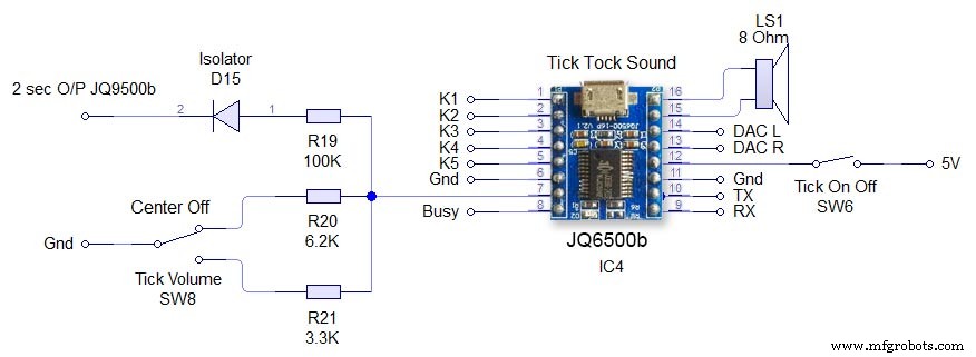
Dies wird direkt über die Hardware des JQ6500 gesteuert. Schalter SW6 Tick On/Off trennt nur die Stromversorgung des JQ6500. Tick Volume SW8 ist ein 3-Wege-Mittelverriegelungsschalter. Durch Betätigen des Schalters nach oben oder unten wird die Lautstärke über den ADKey-Pin am JQ6500 eingestellt. Der Befehl zum Abspielen des Tick-Tack-Sounds kommt alle 2 Sekunden vom Arduino. Die Sounddatei muss kürzer als 2 Sekunden sein. Diode D15 isoliert den ADKey vom Arduino-Ausgang.
Schritt 15:Lautsprecher
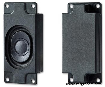
Die Soundmodule sind jeweils mit einem 3W 8Ω Lautsprecher verbunden, der seitlich am Uhrengehäuse angebracht ist. Diese sind als Paar bei Amazon erhältlich.
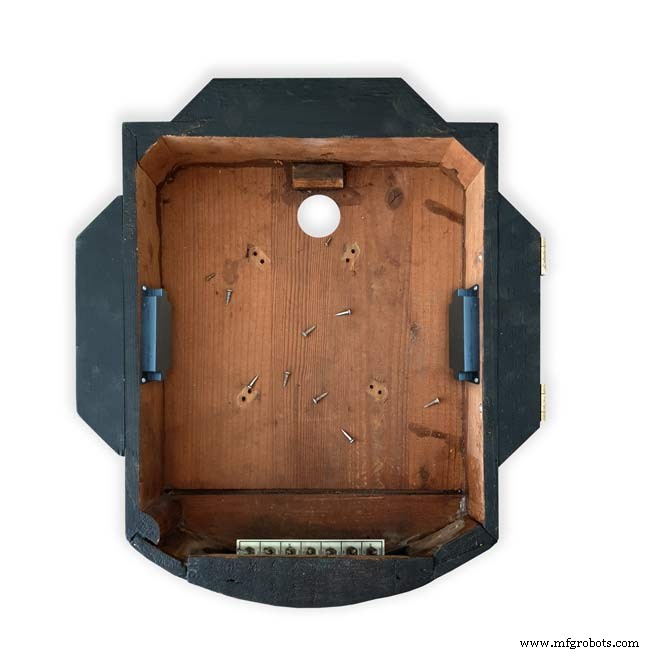
Dieses Bild zeigt die Lautsprecherpositionen im Uhrengehäuse. Beachten Sie das hochgeklappte Schalterbedienfeld unten in der Uhr.
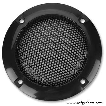
2 Lautsprechergitter decken die Lautsprecher ab und waren ebenfalls von Amazon
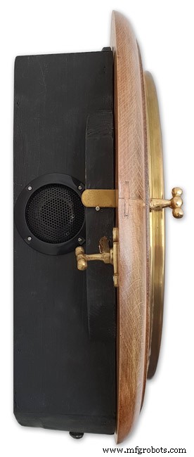
Linke Seite der Uhr mit Lautsprecherposition. Dies wird auf der anderen Seite wiederholt.
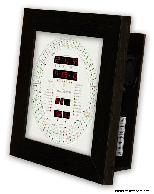
Uhr im Bilderrahmenstil, die den rechten Lautsprecher zeigt.
Schritt 16:JQ6500 Laden von Sounddateien
Ihre Sounds müssen auf das JQ6500-Modul geladen werden.
Auf diesen Seiten finden Sie Informationen und Arduino-Bibliotheken für diese Module.
Arduino-Bibliothek JQ6500_SerialAllgemeine InformationenJQ6500-Tools
Normalerweise ist auf dem JQ6500 ein Musik-Uploader-Programm vorinstalliert, das bei Verbindung mit Ihrem PC geladen wird (funktioniert nicht auf MACs!). This is in Chinese there are instructions on my site here showing how to use the Chinese version.
My JQ6500s came without a loader program so I downloaded an English version from Nikolai Radke
You can get the zip file from here English Language MusicDownload.exe v1.2a
JQ6500_English_MusicDownload_V1_2a.zipI just run this file from windows (no need to install it) and it runs in English see details below.
Insert your JQ6500 into PC via USB.

When the file is run this window will open. Click FILES
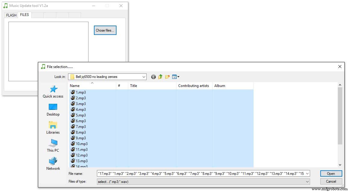
Click CHOSE FILES and shift select all the files you want to be copied to the module. Note make sure your files are named as below.
1 to 12 are the hour chimes. 13 to 16 are the quater chimes and 17 is the test chime used when setting the chime volume using the Chime Volume Switch.
Click OPEN above then click on the FLASH tab.

Click on FLASH and you should get a message saying FILE PROCESSING It the files will fit on the module the message will change to FLASHING RUN and a green bar will show progress.
When flashing is completed the message will change to READY......You can remove your module and plug it into sound board on the clock.
Repeat this for the Tick Tock sound (1 file this time) on the 2nd module.
Sound files are enclosed. I mixed these sound files up on Audacity pic 4 at 48KHz sample rate the max quality the JG6500 board can handle. The chimes were mixed on multiple channels to get the real harmonics then mixed back down to a single channel for the JQ6500.
bell.zip tick_tock.zip
Step 17:JQ6500 Library Modification
Modify the JQ6500_Serial.cpp file in your Arduino libray folder
Using the standard library every time a chime is played the library waits in case there is a reponse. This wait causes the clock run out of sync and any received data errors until the next minute.
I found this on google and is a reply from the author of the library. ~~~~~~~~~~~~~~~~~~~~~~~~~~~~~~~~~~~~~~~~~~~~~~~~~~~~~~~~~~~~ Before sending a command, the library waits for up to 10ms to see if there is any left over data from the device... https://github.com/sleemanj/JQ6500_Serial/blob/ma... after sending the command the library waits for a response for up to 1000ms
https://github.com/sleemanj/JQ6500_Serial/blob/ma... and after that it will wait at least 150ms while reading the response
https://github.com/sleemanj/JQ6500_Serial/blob/ma... since in the case of playFileByIndexNumber you don't need a response at all
https://github.com/sleemanj/JQ6500_Serial/blob/ma... you could perhaps get away with adding if(!responseBuffer &&!bufferLength) return;immediately after the last command byte is written (currently line 263 of JQ6500_Serial.cpp)
https://github.com/sleemanj/JQ6500_Serial/blob/ma... that should reduce the time required to about 10-20ms probably.
~~~~~~~~~~~~~~~~~~~~~~~~~~~~~~~~~~~~~~~~~~~~~~~~~~~~~~~~~~~~~~~~
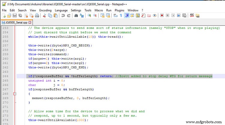
After adding the line after line 263 if(!responseBuffer &&!bufferLength) return; the clock worked fine.
Step 18:Modify the Real Time Clock RTC
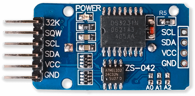
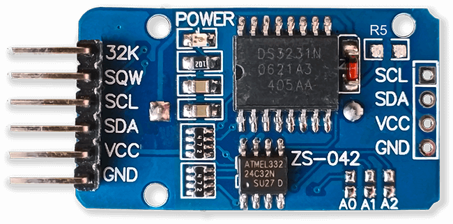
Modification of DS3231 AT24C32 I2C Precision Real Time Clock Module
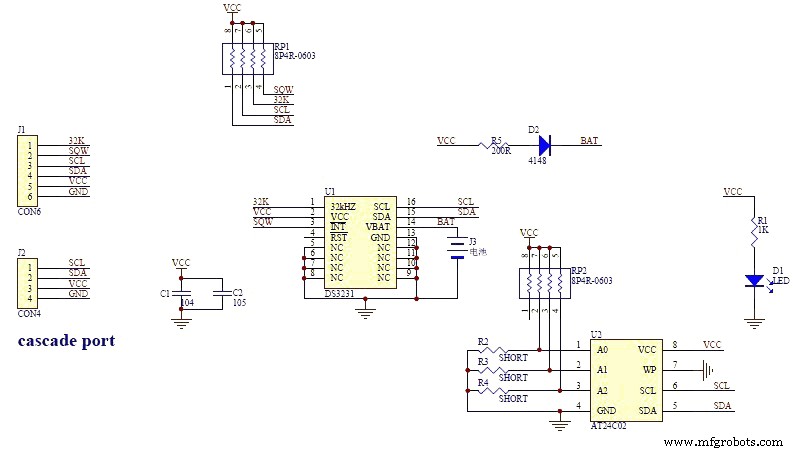
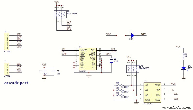
My clock uses a DS3231 AT24C32 I2C Precision Real Time Clock Module.The module comes supplied with a Lithium-Ion rechargeable battery see pic 1. I use a non rechargeable battery so have removed resistor R5 from the module as pic 2.
Step 19:Dial Construction Drawing
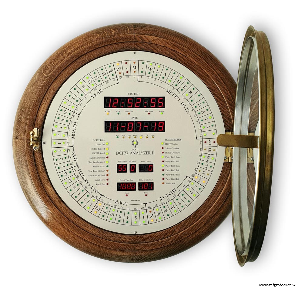
The dial requires oround 700 seperate drilling operations and numerous aounts of cutting and filling to complete.
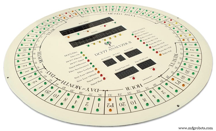
I don't have a CNC machine so it was all done by hand.
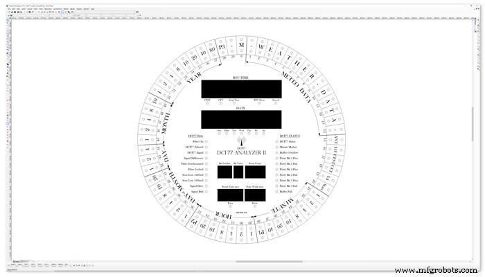
The dial was drawn up on a Cad program (TurboCab) pic 4 and printed out onto injet water slide decal paper.
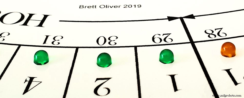
This shows a close up of dial printing with 3mm LEDs to give an idea of scale. The quality from the water slide decal paper is very good far better than my old ink jet can print.
The enclosed zip file contains the dial picture in various file formats including a 4000x4000 png file.
Contact me for other file types!
TurboCad_Drawings.zip
Step 20:Dial Construction Cutting Out &Drilling
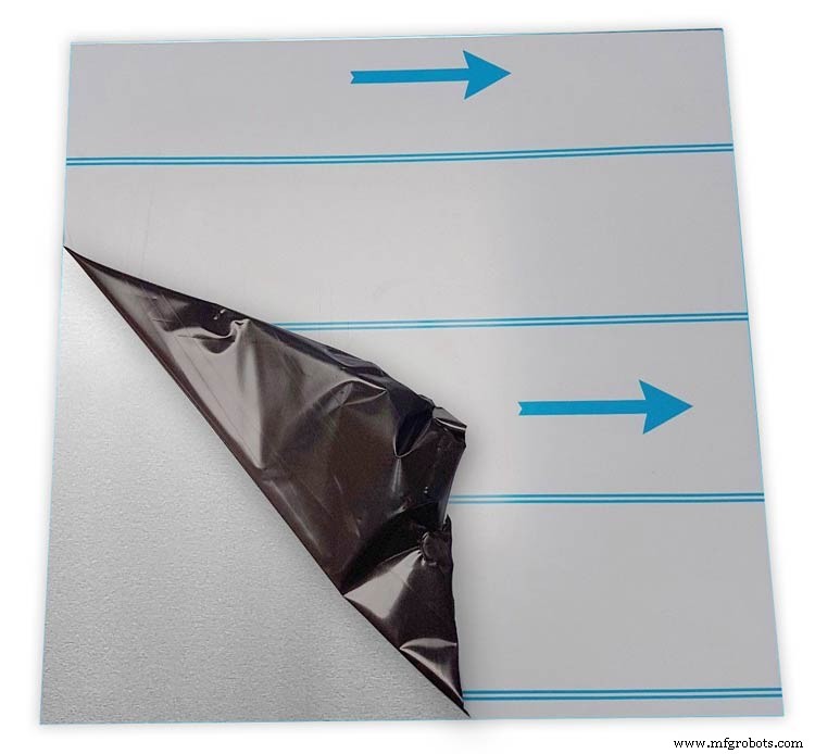
The dial is cut from 1.5mm thick alluminium sheet as it has to carry the weight of all the electronics and wiring.
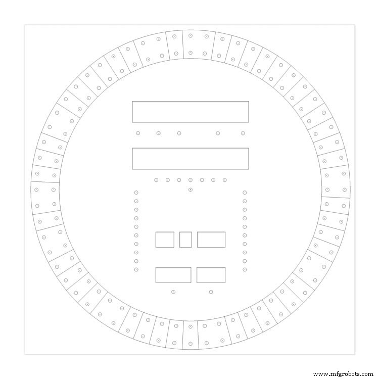
Make a template by printing out the dial from your CAD program onto A3 paper.Make sure it has center marks for the LED holes and also the cutouts for the 7 segment LED displays.
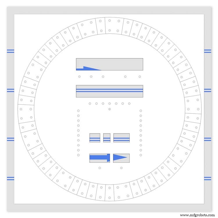
Carefully cutout the 7 segment display openings on the template with a craft knife.Place the template on the alluminium sheet and tape it down to stop it moving. Center punch all the center marks for the LEDs and draw around the openings for the 7 segment displays with a marker pen.
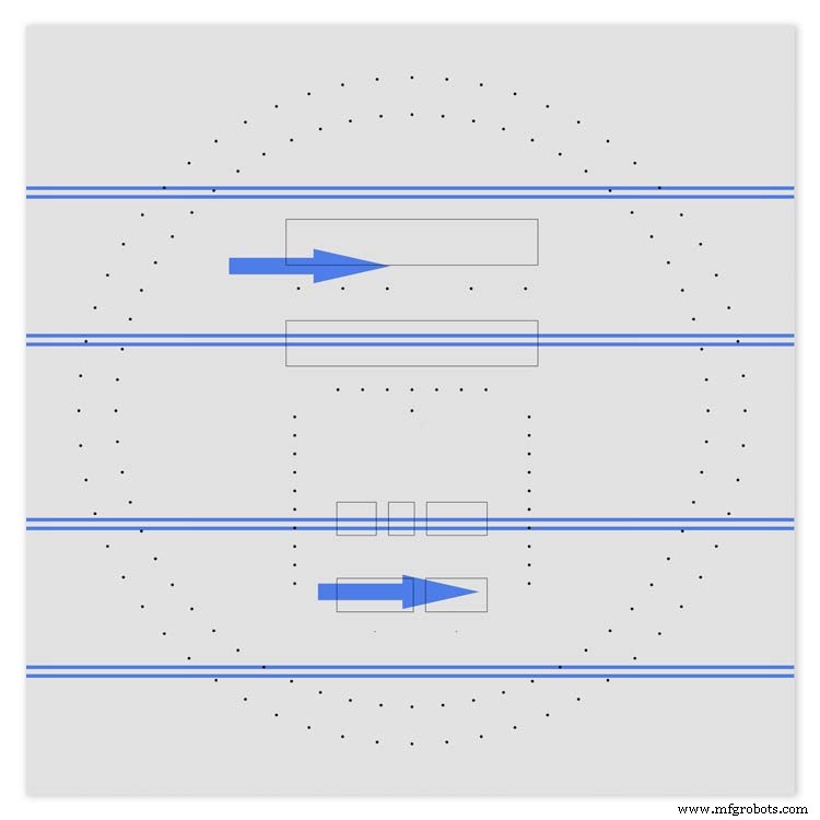
Remove the template to reveal the cutting/drilling marks on the alluminium sheets protective film.
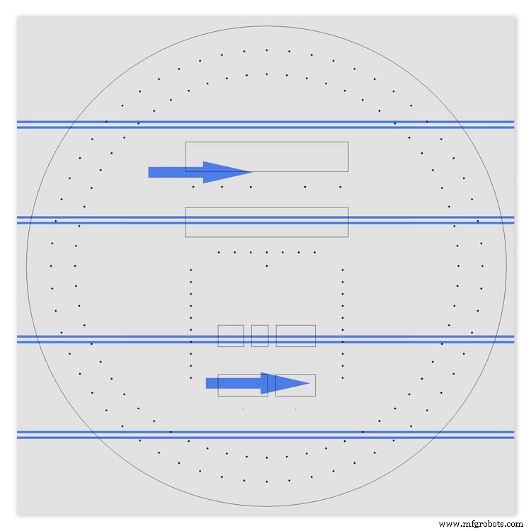
Draw a circle the size of your dial with a compass using the center punch mark from the DCF77 symbel LED as a center point.
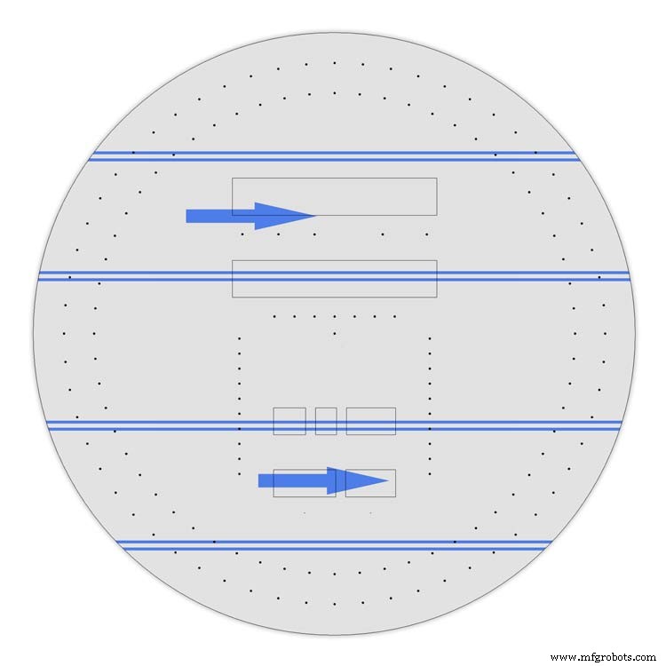
Cut out the circle with a hacksaw/jigsaw or bandsaw fitted with a metal cutting blade.
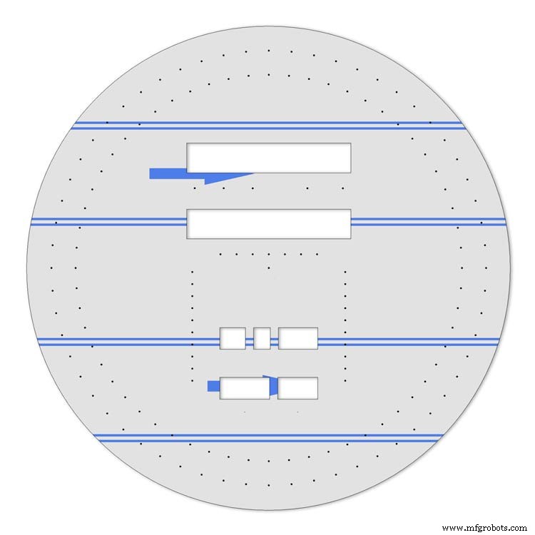
Cut out the 7 segment display openings with a coping/jig or fret saw. Take your time with this as it will save a lot of filing later.
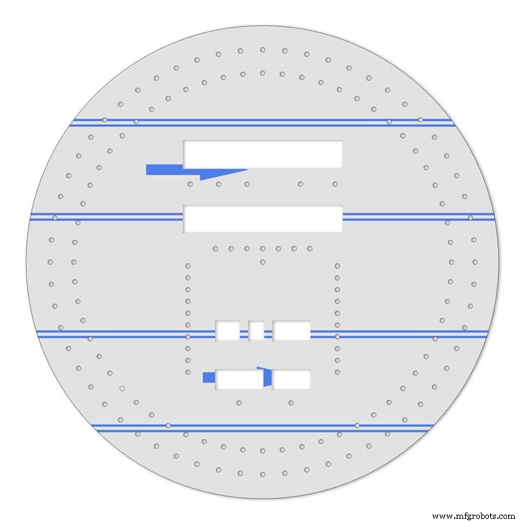
Drill out all the holes for the LEDs. I start with a 1mm bit then a 2mm and then finally a 3mm bit.
This leaves the LEDs a friction fit once the paint and varnish is applied to the dial.
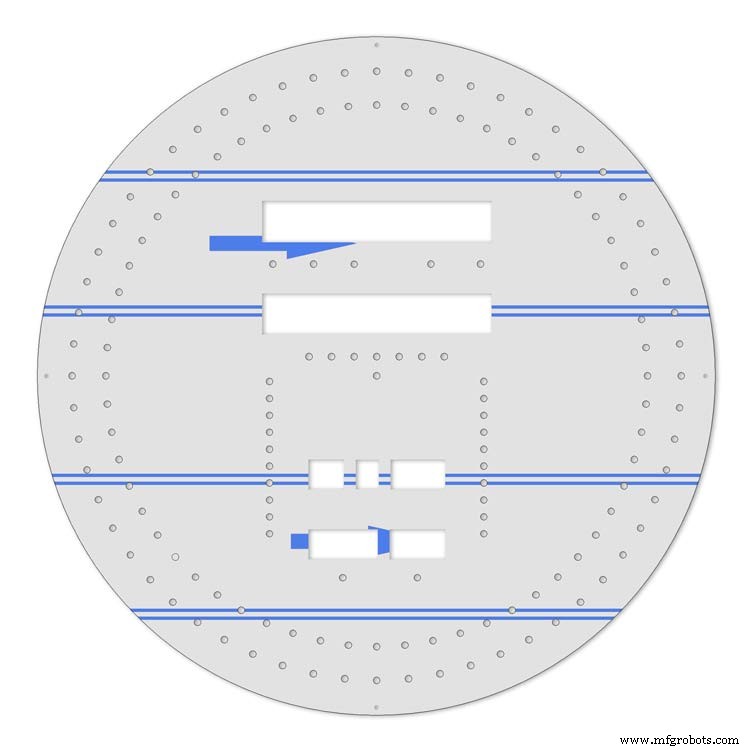
Mark center punch and drill 3 or 4 dial mounting holes.
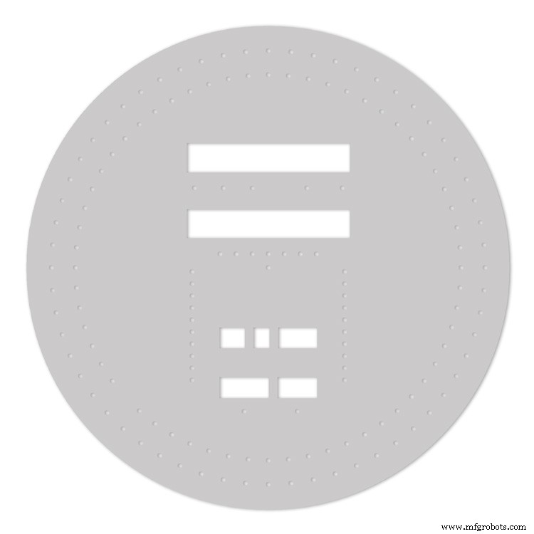
With the holes drilled the protective film can be removed from the alluminium sheet and the dial rubbed down to remove all rough edges.
This will also give a good key for the paint.
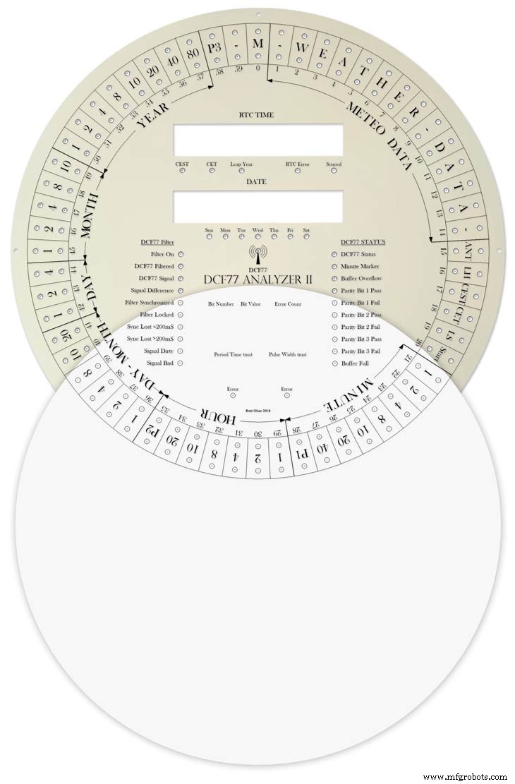
Prime and paint with acrylic paint then a coat of matt varnish. Antique White looks better on old dials or use pure white on modern dials.
Step 21:Dial Construction Applying the Dial Transfer Decal
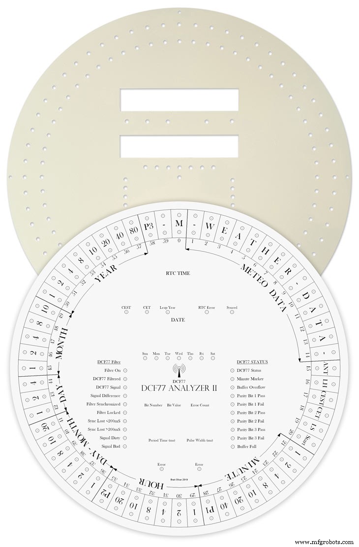
Water slide decals are printed out on special paper on an inkjet printer. Once dry they are soaked in water then slid into place.
They give a very detailed print and once given a coat of varnish are tough. Don't forget to order transparent tranfers so the dial colour can be seen through the transfer. Follow the instructions with the pack as they do vary.
On my transfers I print out the dial on transfer paper let it dry and then cut it out to just under the size of the dial. I then give it a coat of acrylic varnish. When the varnish is dry the transfer is soaked in water until the transparent transfer comes away from the white backing sheet.
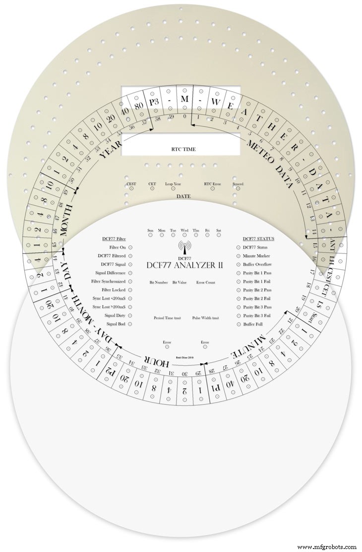
Line up the transfer with the dial and slide it over the dial.

Make sure the center dots line up with the center of the holes in the dial then slide the backing sheet back off the transfer.
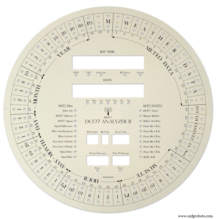
Carry out any final adjustments then remove any airbubbles.
Allow to dry then apply some clear acrylic varnish to protect the transfer. Once this dries carfully cut away the transfer around the 7 segment display cutouts with a craft knife. Then cut the transfer off all the LEDs hole. I used a leather punch just smaller than the hole. Give it another coat of varnish to seal all the cut edges Leave it overnight to dry.

Search for "Transparent Water Slide Decal Paper A3"
Step 22:Dial Construction PCB/Vero Board Mounts
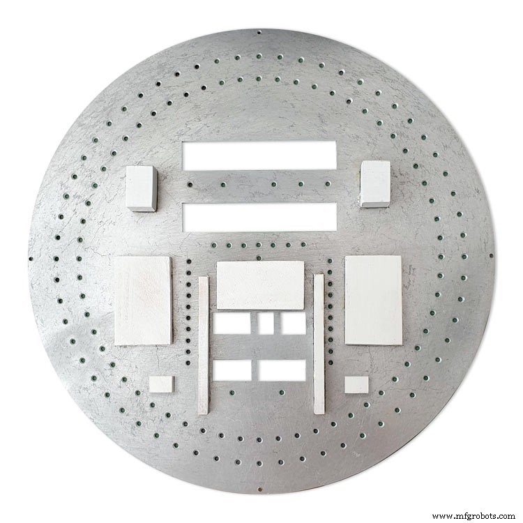
The PCBs and Vero Boards are fixed to wooden mounting blocks cut from off cuts of timber.These block are glued to the dial with impact adhesive. Follow the instructions on the impact adhesive but normaly you apply to both surfaces leave until tacky then press together for an instant bond that hardens fully over night.
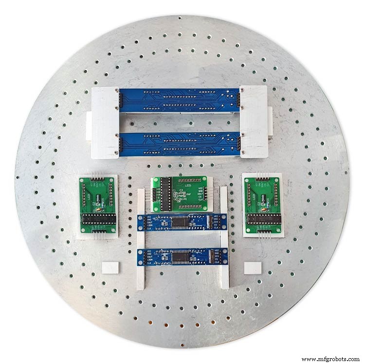
Lower modules in position on the wooden blocks ready to be secured by M2 screws.The main PCB fits on top of the lower 7 segment modules and is raised up on brackets.
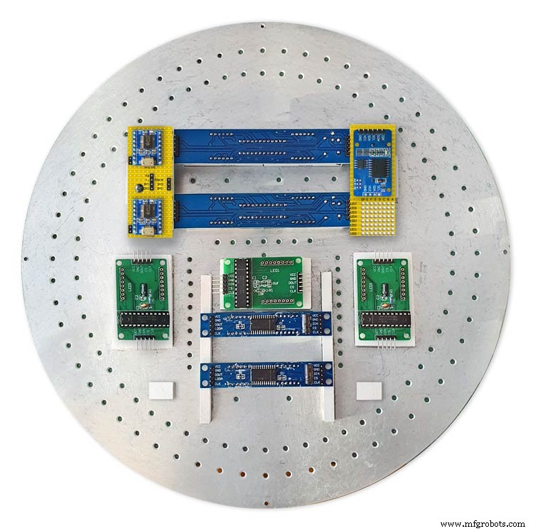
JQ6500 sound module board and LED wiring board in place. RTC is mounted on the LED wiring board but connected on the main board.
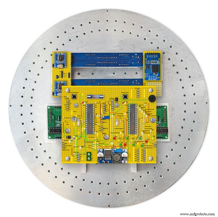
Main board mounted on custom made standoff brackets.
Step 23:Dial Surround &Back Box Restoration
Dial Surround Restoration
I sourced my clock case from eBay. It had no dial or brass bezal and the rear box was broken.
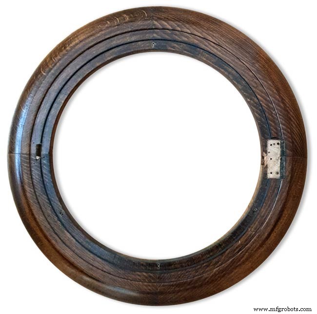
The original Oak dial surround was covered in a thick coat of varnish and years of dirt.
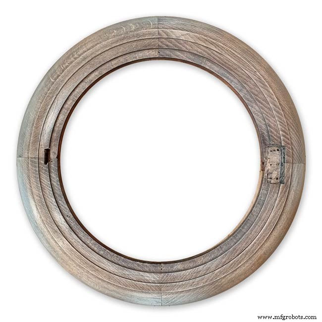
I used paint stripper to remove the varnish and then wood bleach to get rid of the very dark areas of wood.
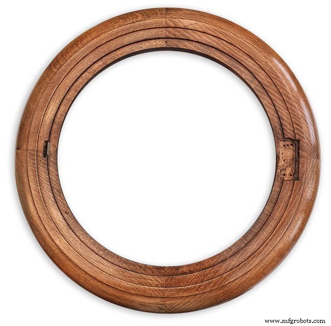
The surround was then varnished with matt acrylic to enhance the grain of the wood.
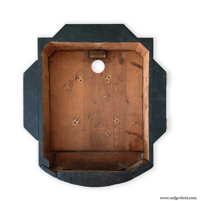
The back box was very badly damaged and had to be screwed and glued back together. I has to fill many hole and cracks in the wood work and decided to paint it matt black.
Step 24:Correcting MAX7219 7 Segment Module Display Errors
The 7 segment modules seem to work fine work fine on their own. However, once you start daisy chaining them together the displays tend to error.
0.39" Display

The datasheet calls for a 10μF and 0.1μ capacitor across the supply rails as close to the MAX7219 as possible.I notice the 0.1μF capacitor is in place but the 10μF capacitor is missing.
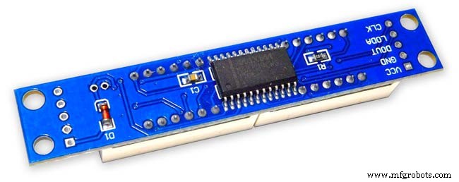
Add this capacitor in the 2 holes above the diode D1 on the rear of the display.
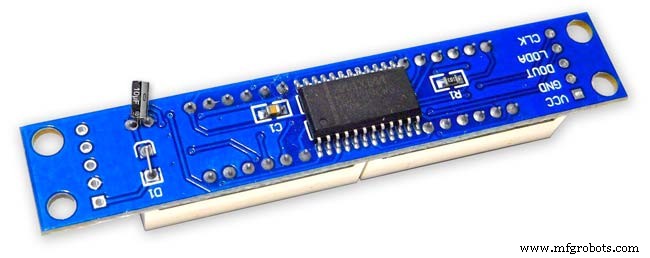
There is also a diode in series with the supply rail. When daisy chaining modules all these diodes are in series so the further down the line of modules the more volts are dropped causing display errors.
Remove this diode on each display and replace it with a wire strap.
0.56" Display

Note the black tape over the 3rd and 6th digit tp make colons.

10μF capacitor added to the rear of the PCB on the +&- pins of the MAX7219 IC

The 1N4148 diode is replaced by a wire link.
Step 25:Increasing the Constrast on the 7 Segment Modules
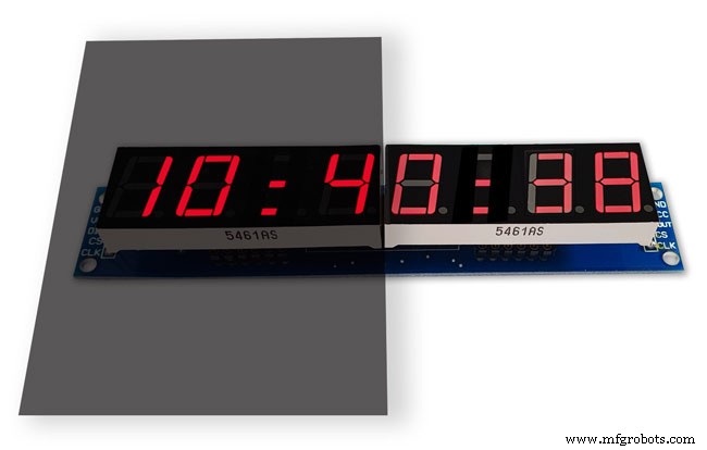
The 7 segment displays traditionally would have a sheet of red perspex to match the LED colour placed over the top of the display. This was designed to hide the not lit segments and provide contrast to the LED segments that are on.
In my clock I have used Neutral Density Heat Proof Dimming Transparent Acetate Sheet ND 0.9.
This hide the not lit LED segments and provides the contrast needed in bright conditions. It has the advantage that it work on all colour LEDs.
My 0.56" modules are a deeper red than the 0.39" modules so I would need 2 different matching red perspex to sheets to work well on both modules.
The acetae shhet is also very cheap the only disadvantage is that it is too flimsy to cover large areas without support.
The picture above shows the effect of the ND sheet. The lit LED segements have more contrast and the unlit LED segments are hidden. It also hides the black tape masking for the colon display.
Step 26:Modification of the RTC Time 7 Segment Display Module to Show Colon Digit Seperators

The standard display only has decimal points to separate the digits and has no colon that would normally be used in a clock display.

In code I have set digits 3 and 6 to always display a "o" lower case o

Black plastic tape is then cut with a craft knife and placed over the 2 digits leaving a small section showing

When the display is on these visible sections now display colons
Step 27:Dial &Case Fitting
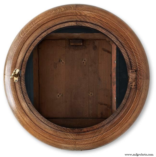
The dial is hidden behind a brass bezal. The brass bezal was missing from my clock but I was able to get one from a horological supplier.
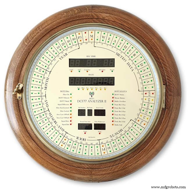
The brass bezal is held down by a brass catch set into the dial surround.

With the brass bezal removed you can see the recess cut in the surround for the brass bezal hidge. My new bezal hinge was a differnet shape to the original hinge so I had to cut it in with a chisle at the front and fill the rear in with a piece of wood stained to match the surround.

The dial has been removed showing the dial mounting holes on the wood surround and the wooden back box behind it.
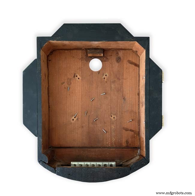
Shows the surround removed revealing the back box construction. The switch panel can be seen folded up above the trap door in the base of the back box.
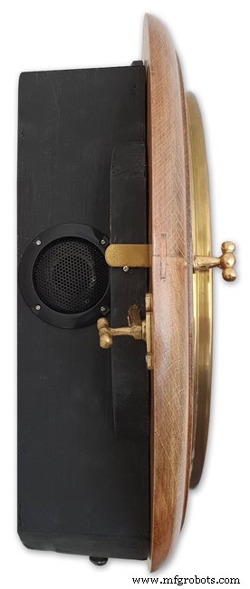
Shows the side view of the case with dial and wood dial surround locked in place. The dial surround is locked by the same type of catch used to lock the brass bezal in place. Note the small brass screw below the brass tag on the dial bezal. this ensurse the brass bezal lines up correctly with the dial when the brass bezal is closed.
Step 28:Dial &Case Fitting Modern Style Case and Surround
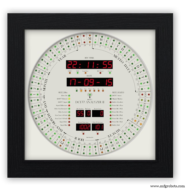
This case uses a large picture frame with a basic square back box to hold the electronics and to hold the dial away from the wall to give it some depth.
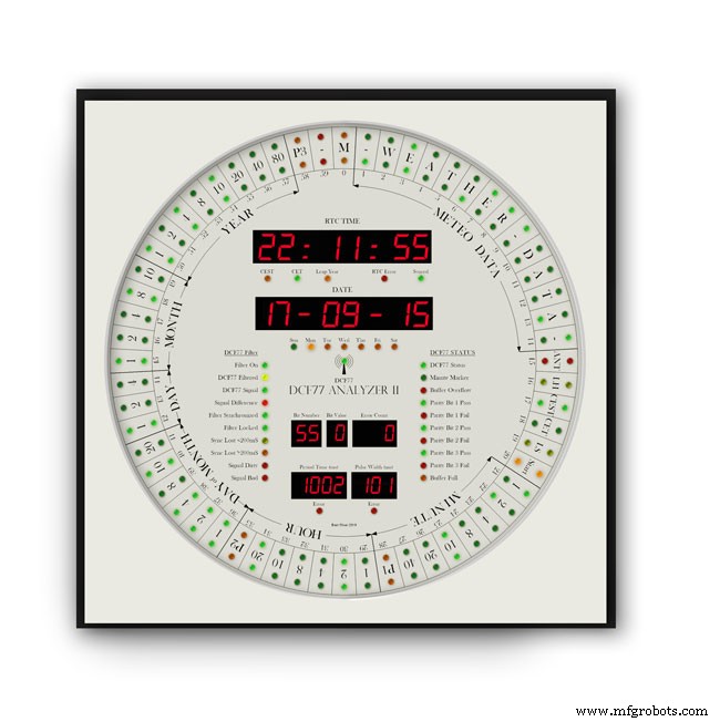
Outer frame and glass removed to reveal the thick photomount card over the dial (a thin ply or wood sheet can also be used with a routed edge)
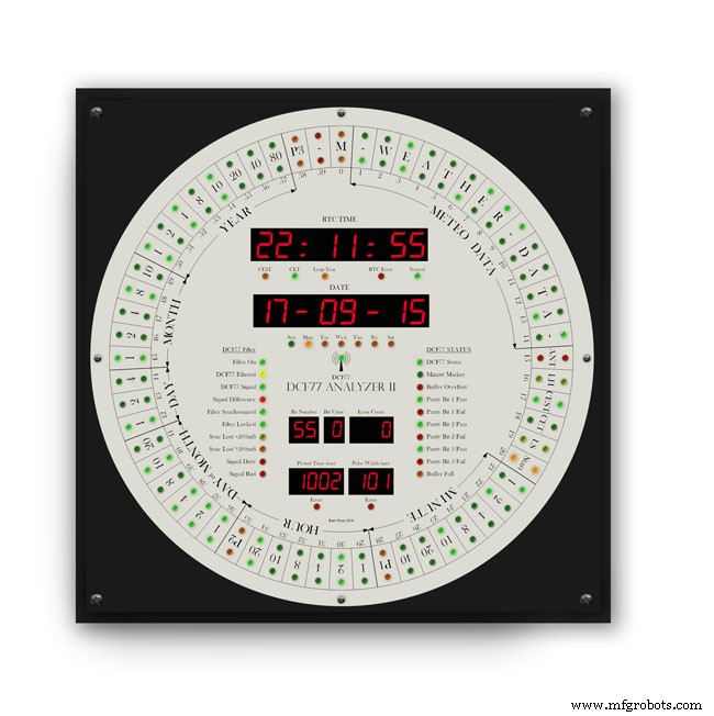
Photo mount removed to show how the dial is fixed to the back plate with 4 small screws.
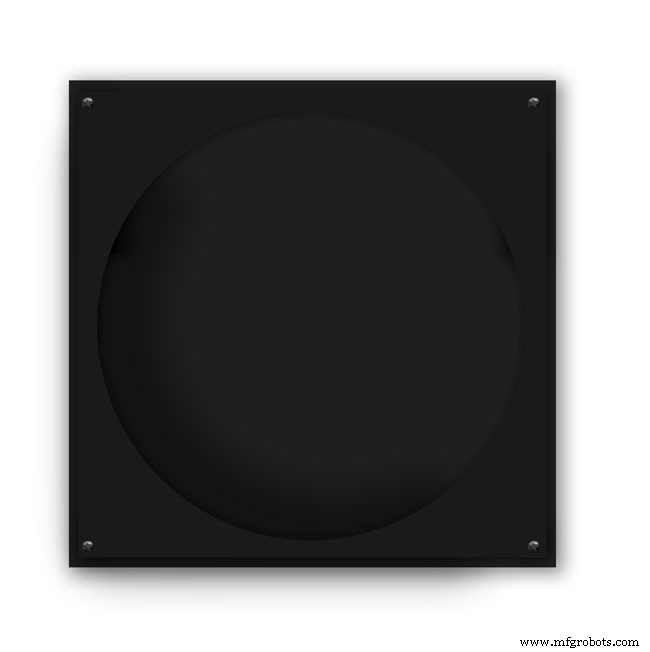
The backplate holds the dial and has a large circular cutout for the electronics.

It is hinged at one edge to the dial can swing out.
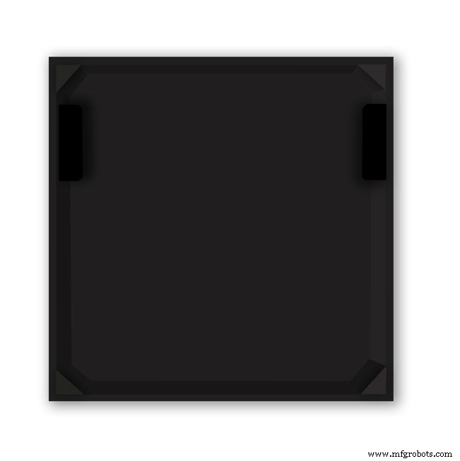
The speakers are mounted on both sides with holes and grills as per the other case.
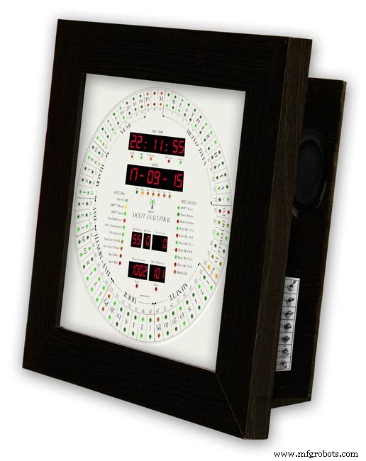
The switches are mounted on the side in a cutout with the speaker grill above.
Step 29:DCF77 Filter
DCF77 Filter
When switched on the Udo Klein's Super Filter actively processes the incoming DCF77 signal from the antenna/receiver. After a few minutes of sampling the DCF77 signal the Super Filter will predict the DCF77 signal and use this to determine if the incoming signal contains any errors. The Super Filter will then synthesize a corrected DCF77 signal even if the signal is absent.
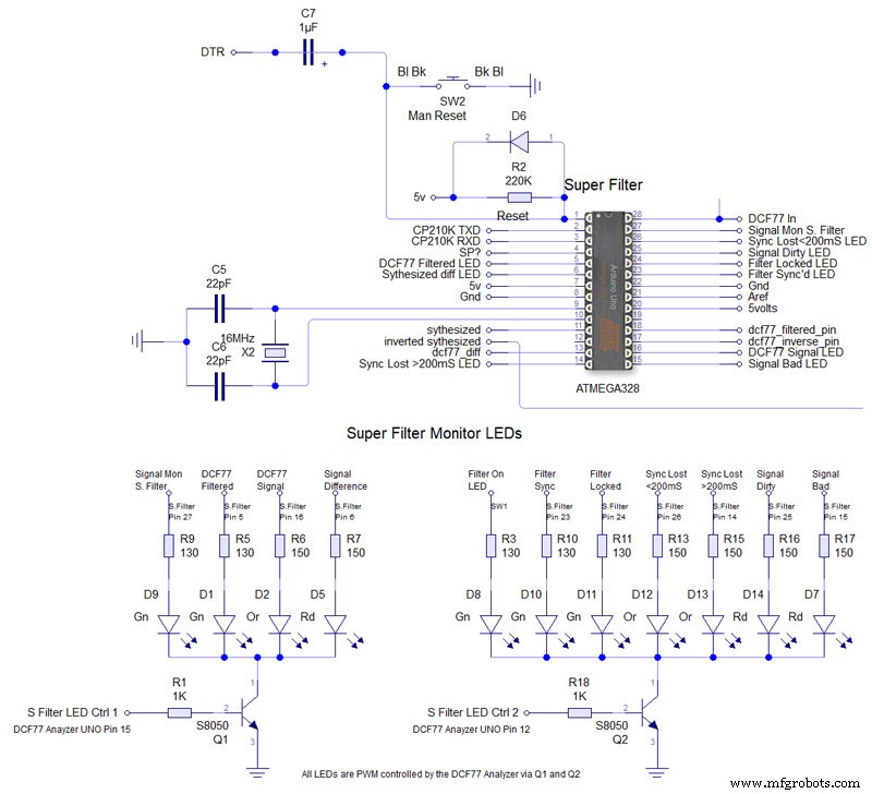
Super Filter Mod See the schematic. I have modified the Super Filter Code to add extra monitor LEDs. In order to do this I have removed 4 modes from the filter just leaving sythesized and inverted sythesized.
Note the PWM LED brightness control is via the Arduino controlling the DCF77 decoding not the Super Filter Arduino. I have also added an LED test to the Super Filter to Match the LED Test on the main clock. This activates on reset or power up. On power up the Supe Filter LED test starts and finishes then the main clock LED terst starts.
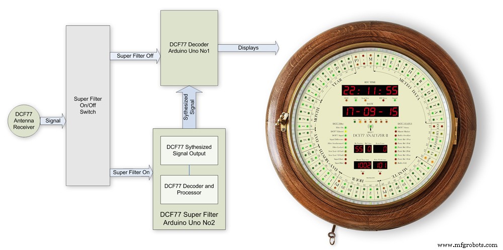
The filter will lock onto the DCF77 signal even if the signal is really noisy. As days progress the filter uses the incomming DCF77 signal to adjust the Arduino crystal frequncy.
This means the filter will stay in time even if the DCF77 signal is lost for many days. In my clock the DCF77 signal is alway fed to the Super Filter Arduino even if the DCF77 Source switch is set to off. This allows the Super Filter to stay in sync and keep adjusting the quartz crystal from the Arduino.
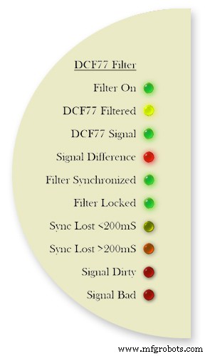
Filter On lights when the DCF77 Source switch is set to FILTER and means the Super Filter is decoding and synthesizing the DCF77 signal
DCF77 Filtered the DCF77 Synthesized signal comming out from the Super Filter
DCF77 Signal the DCF77 signal comming direct from the DCF77 receiver with no filter applied
Signal Difference the differnece between the incomming DCF77 signal and the Synthesized signal. In normal operation this will flash as the received signal shape is often slightly “wider” than the synthesized signal.
Filter Syncronized best possible quality, clock is 100% synced
Filter Locked clock driven by accurate phase, time is accurate but not all decoder stages have sufficient quality for sync
Sync Lost <200mS clock was once synced, inaccuracy below 200 ms, may re-lock if a valid phase is detected
Sync Lost>200mS clock was once synced but now may deviate more than 200 ms, must not re-lock if valid phase is detected Signal Dirtytime data available but unreliable Signal Bad waiting for good enough signal
More details on some of the above
Filter Syncronized - Timing is completely locked to DCF77 and the data is most up to date.
Filter Locked - If the quality factor of the decoder stages drops but the quality factor of the phase decoder stays high enough the clock will transition into the state locked. In this state it is still phase locked to DCF77 but it may become out of sync by a second but only if a leap second is transmitted.
Sync Lost <200mS - This indicates that the quality factor of the decoder stage and the quality factor of the phase decoder have dropped. In this state the timer relies on the quartz crystal timimgs and the clock will slowly drift out of phase with the DCF77 signal. This is a warning that the clock may be running slightly out of sync.
Sync Lost>200mS - Once the clock has started to drift out of phase for more than a set period of time (depending on the tuned accuracy of the quartz crystal) then this LED will light
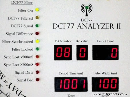
Animation showing filter synchronized
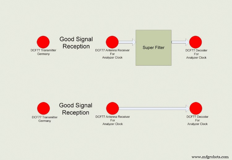
Super Filter example
The top row shows the Super Filter turned on. Once synchronized and tuned into the signal the Super Filter will synthesize a good signal even when the signal is completely lost. On a noisy signal the Super Filter will search for known signal bits and keep itself synchronized to the transmitter. The bottom row shows the Super Filter turned off. Whatever signal is received (good or bad) is sent to the decoder.
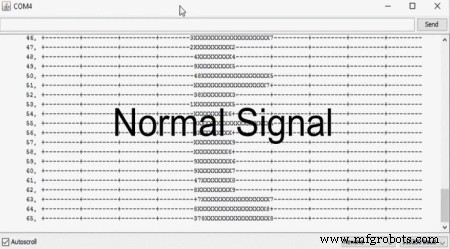
Super Filter correcting a noisy signal as displayed on the DCF77 Scope included with the DCF77 library.
Normal Signal No super filter - Normal signal from the DCF77 reciever Noisy
Signal No Super Filter - The aerial is moved near a LCD screen to generate noiseover the signal
No Signal- The aerial is disconnected and moved connected via the super filter
Noise On Superfilter On- The noise is filtered out leaving a perfect signal.
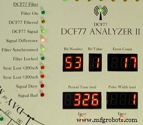
Super Filter turned Off and a bad signal the clock errors and will reject this minutes data.Note the DCF77 Filtered LED pulses as normal but as the Filter is turned off the filtered signal is not fed to the clock's decoder.
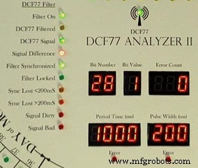
Super Filter turned On and a bad signal the clock has no errors and the clock is able to decode the data as normal.Note the DCF77 Filtered LED pulses as normal and is fed to the clock's decoder
Step 30:DCF77 Time Code
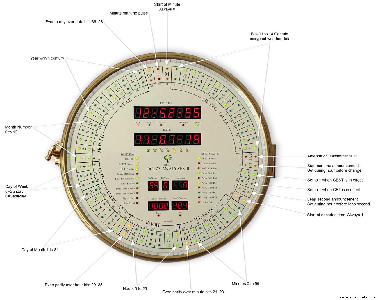
This picture shows the dial code as it is displayed on my dial and allows you to read the incomming DCF77 signal.
Step 31:Code
There are 2 seperates codes to download one for the Superfilter and one for the Analyzer part of the clock.
DCF_77_ANALYZER_CLOCK_Mk2_43.zip Superfilter07DCF77AnalyzerMK2.zip
Code
- DCF77 Decoder Code
- Super Filter Code
DCF77 Decoder CodeArduino
This is the code loaded onto DCF77 analyzer ArduinoNo preview (download only).
Super Filter CodeArduino
This is the code loaded onto DCF77 Super Filter ArduinoNo preview (download only).
Github
https://github.com/sleemanj/JQ6500_Serialhttps://github.com/sleemanj/JQ6500_SerialKundenspezifische Teile und Gehäuse
CAD files for the dial and dial template in CAD formats and also picture files turbocad_drawings_TESmpq119g.zipSound files for loading into the JQ6500 module for chimes bell_wYLvJG1pUl.zipSound files for loading into the JQ6500 module for tick tock sound tick_tock_FLj9XHTJoB.zipSchaltpläne
This is the main board schematic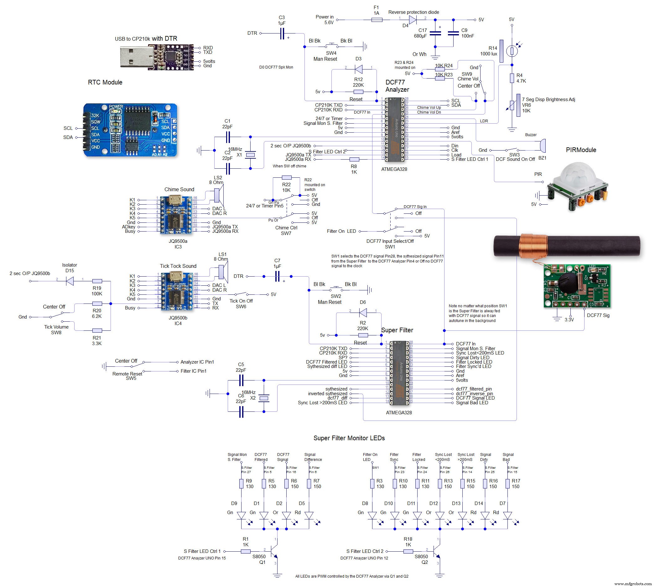 This is the schematic to show the MAX7219 dot matrix module wirng to the LEDs
  This shows the wiring for the MAX7219 7 segment display modules
Herstellungsprozess
- Kuckucksuhr
- Arduino-Pov-Vision-Uhr
- DIY einfachste IV9 Numitron-Uhr mit Arduino
- Einfache Wanduhr mit Adafruit 1/4 60 Ring Neopixel
- Einfache Wordclock (Arduino)
- Arduino-Uhr mit islamischen Gebetszeiten
- Arduino Spybot
- Hauptuhr
- Arduino-Temp. Monitor und Echtzeituhr mit 3.2 Display
- Einfacher Wecker mit DS1302 RTC


