


Arduino-Barometer
Komponenten und Verbrauchsmaterialien
 |
| × | 1 | |||
 |
| × | 1 |
Über dieses Projekt
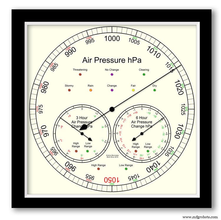
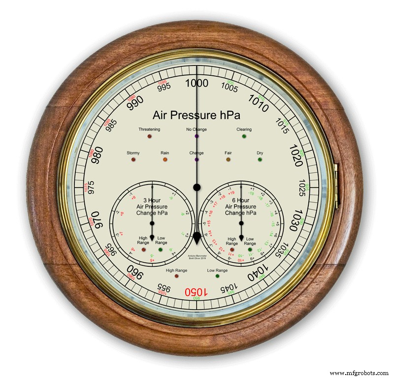
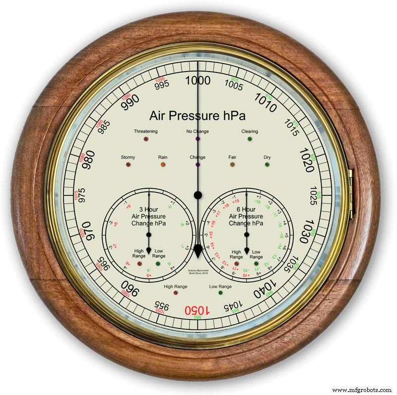
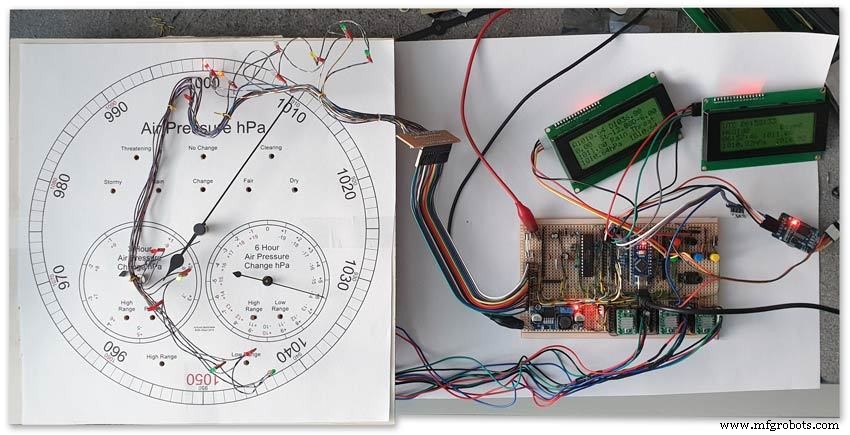
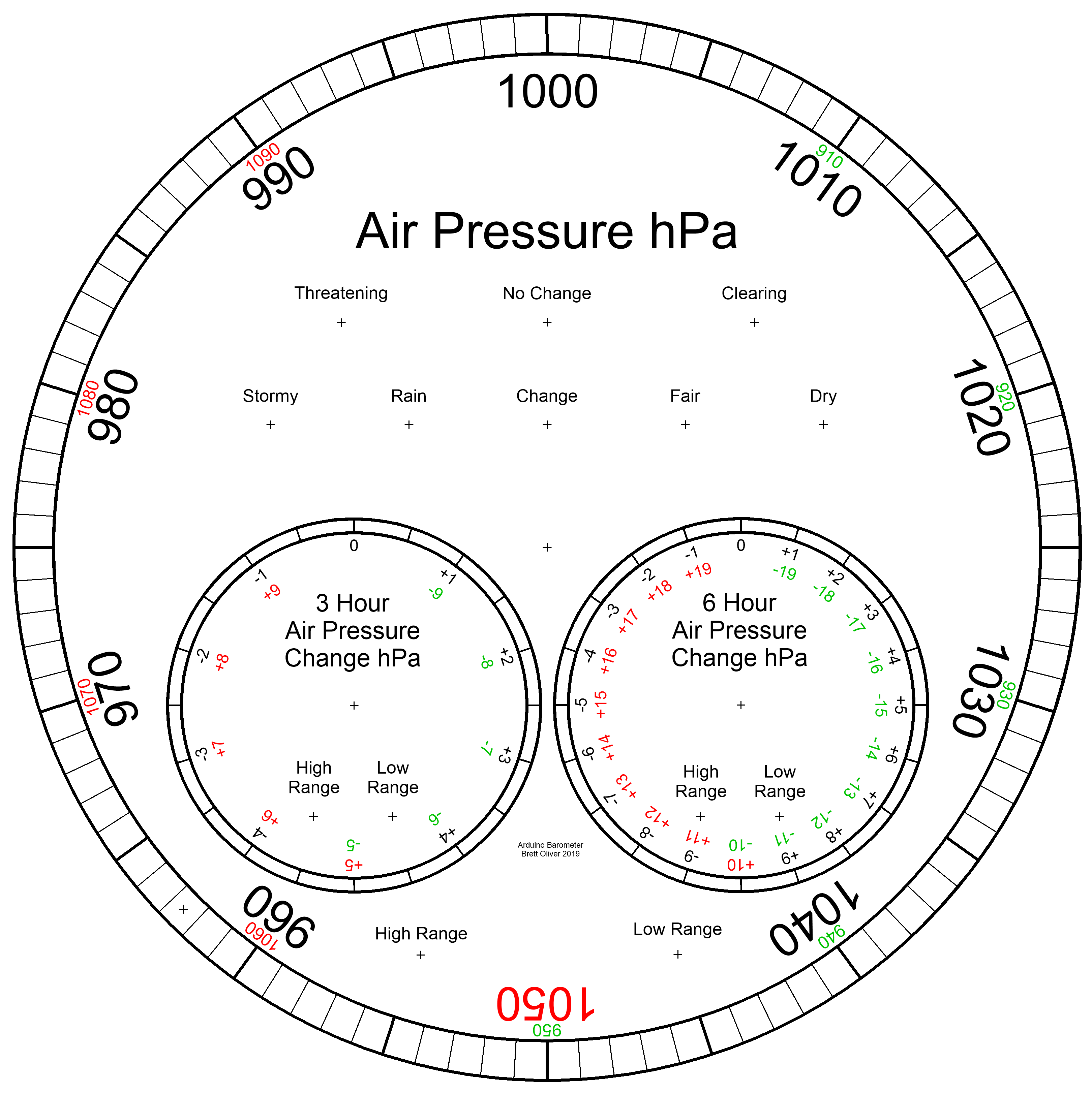
Verwenden eines Arduino UNO und Nano zur Anzeige des Luftdrucks auf einem 12" (300 m) analogen Display mit 3 Schrittmotoren.
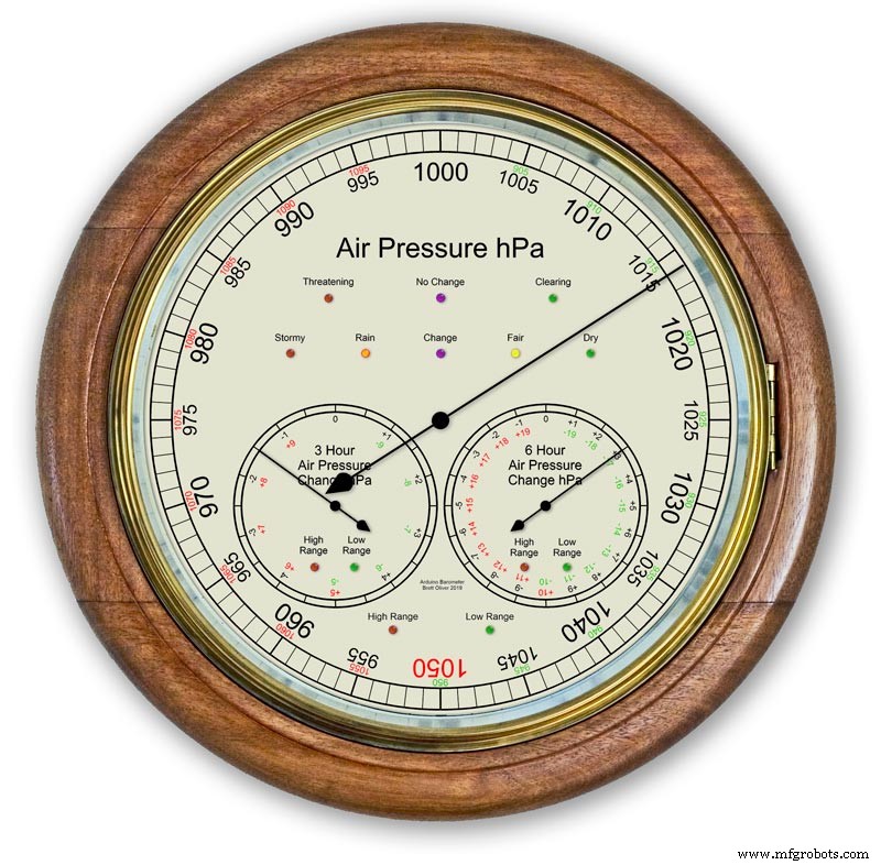
Zur Auswahl stehen 2 moderne und klassische Zifferblattdesigns.
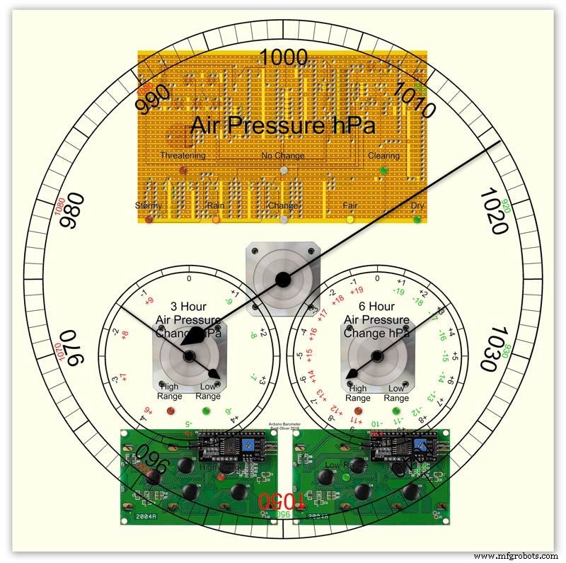
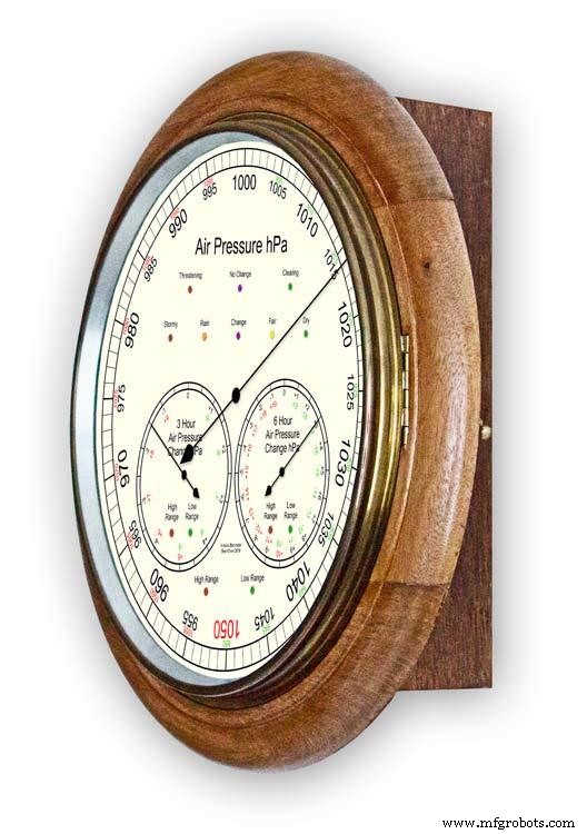
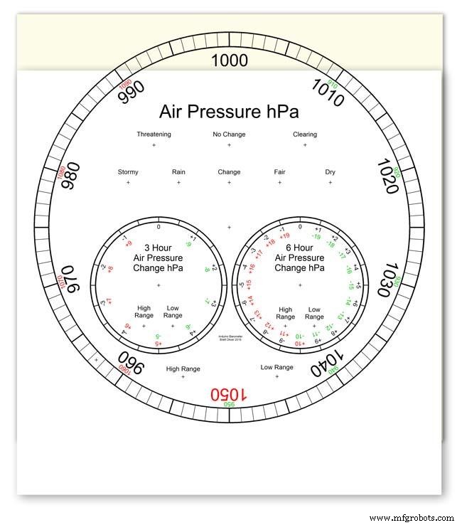
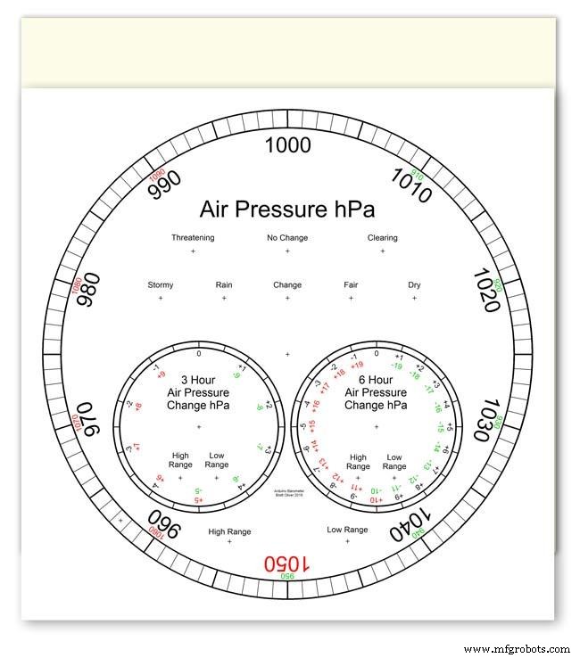
Der Luftdruck in hPa (Hektopascal) wird auf dem großen Hauptzifferblatt angezeigt und alle 10 Minuten aktualisiert.
Es gibt 2 sekundäre Zifferblätter, eines zeigt die Druckänderung der letzten 6 Stunden und das andere die Druckänderung der letzten 3 Stunden an.
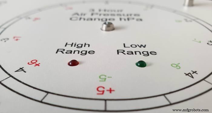
Das 3-Stunden-Zifferblatt hat eine erhöhte Auflösung von 0,5 hPa, da dies für die Wettervorhersage verwendet wird. Es gibt LEDs, die auf allen drei Displays anzeigen, wenn die erweiterte Reichweite verwendet wird, und auch LEDs, um die Wettervorhersage außerhalb des 3-Stunden-Displays anzuzeigen.
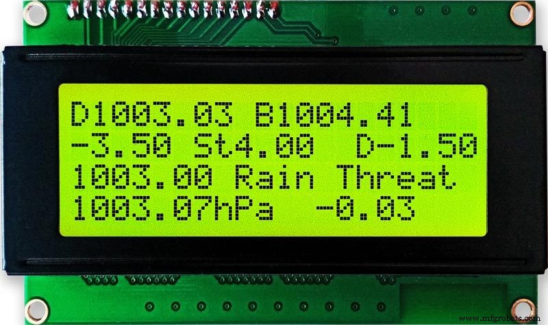
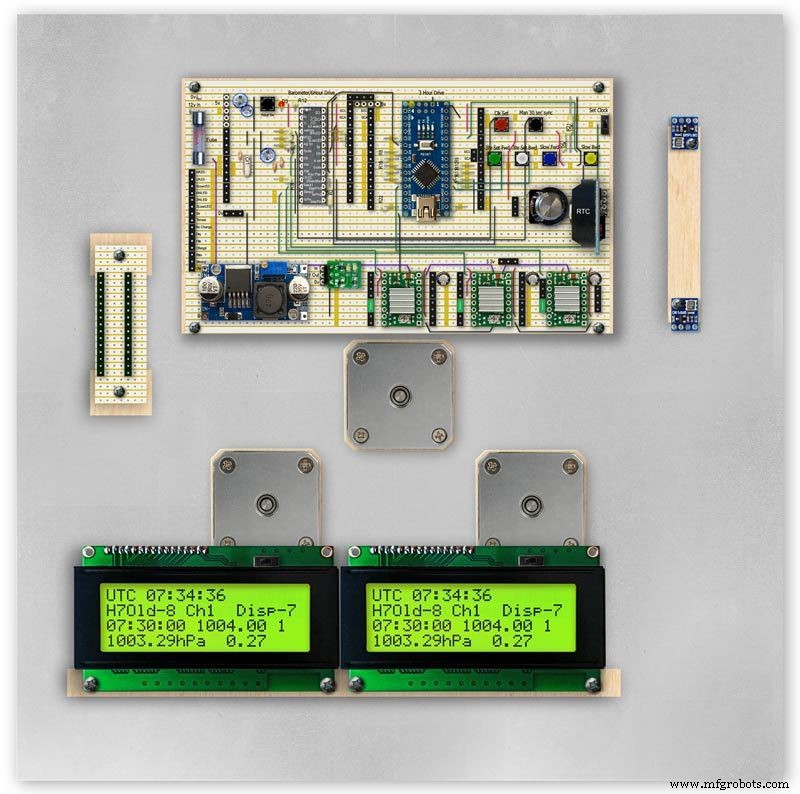
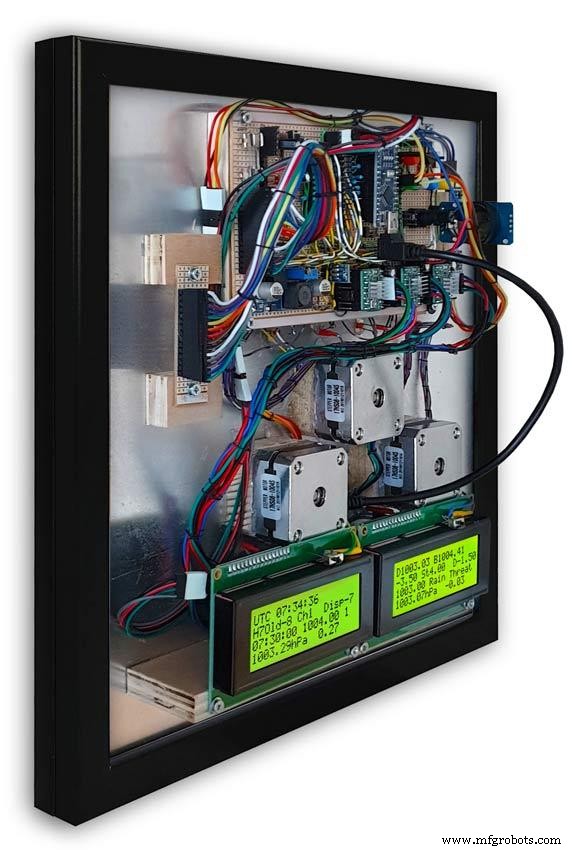
Im Inneren des Gehäuses zeigen zwei 20x4 LCD-Bildschirme Informationen von jedem der Mikroprozessoren.
Die Hauptluftdruckanzeige und die 6-Stunden-Anzeige werden von einer RTC gesteuert. Diese Uhr liefert auch einen 1-Stunden-Impuls für die 3-Stunden-Anzeige.
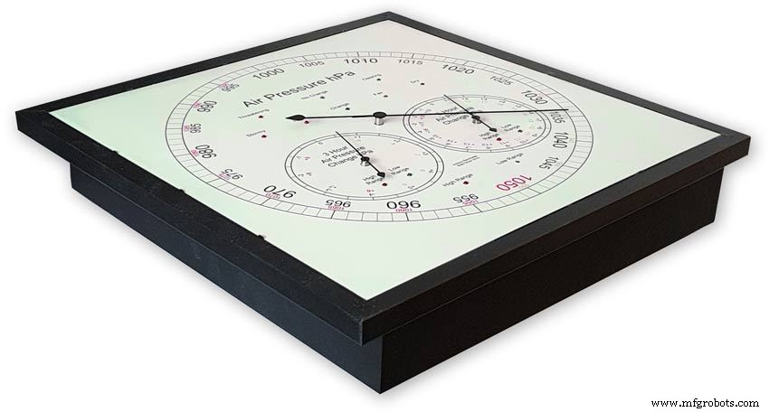
Schritt 1:Vergleich mit einem herkömmlichen analogen Barometer

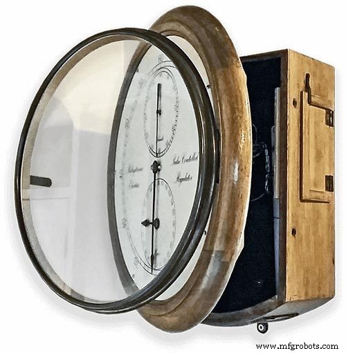
Die meisten analogen Barometer pic. 2 Verwenden Sie einfach den Luftdruck als Anhaltspunkt, um das Wetter vorherzusagen, und Sie müssen daran denken, den beweglichen Zeiger einzustellen und die Zeit zu notieren, um die Luftdruckänderung zu sehen.
Das Wetter wird einfach um das Zifferblatt geschrieben und am Zeiger abgelesen. Die Vorhersage ist etwas komplizierter, da Sie den 2. Zeiger verwenden und jede Änderung über einen Zeitraum von 3 Stunden notieren müssen. Sie müssen sich die Kombinationen aus aktuellem Druck und steigendem/fallendem Druck merken, um Ihre Vorhersage zu erhalten.
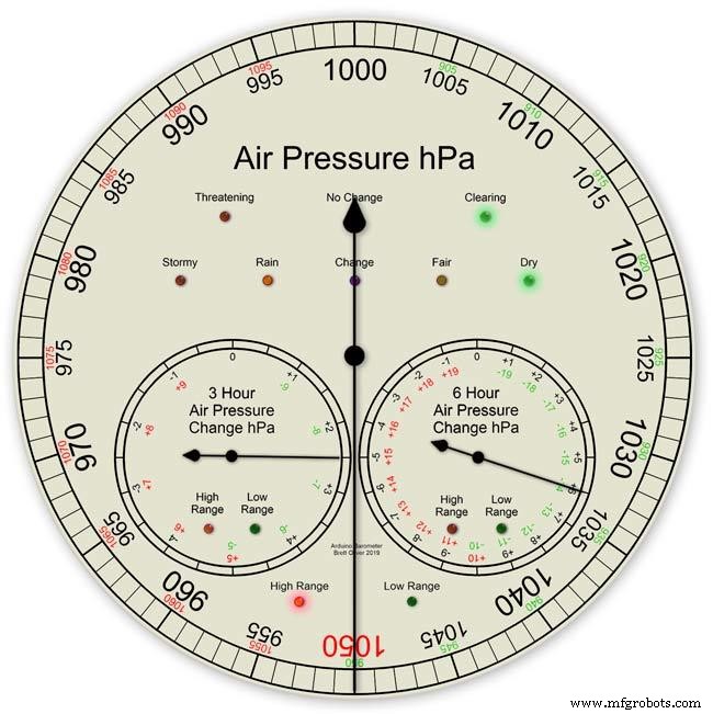
Mein Barometer überwacht kontinuierlich die Druckänderung über einen Zeitraum von 3 Stunden und 6 Stunden und zeigt diese Messwerte auf 2 separaten Zifferblättern an.
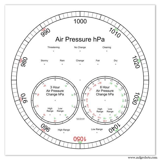
Bild 1 zeigt die Wettervorhersage meines Barometers.
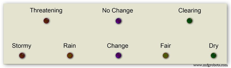
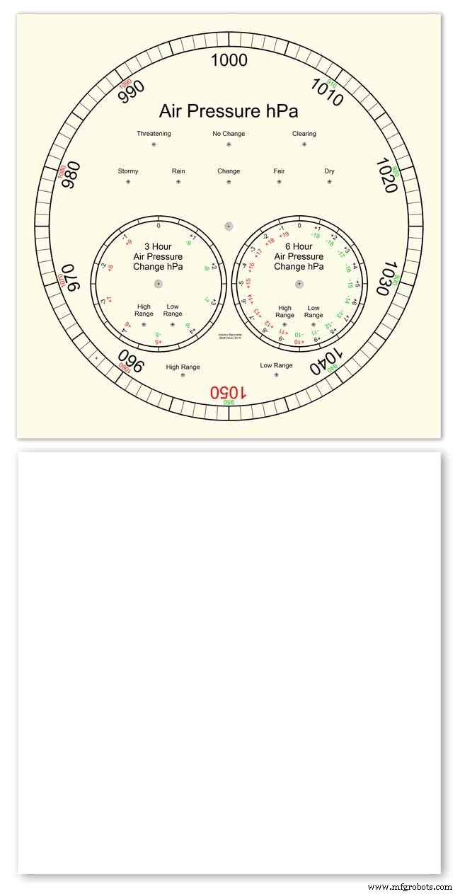
Bild 3 zeigt eine Nahaufnahme der Wettervorhersage-LEDs. Die Wettervorhersage basiert auf der Luftdruckänderung der letzten 3 Stunden.
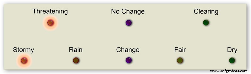
Schritt 2:Barometer-Demo zur Vorhersage eines Sturms

Diese Zeitraffer-Animation zeigt, wie die Barometer-Zeiger und die Vorhersage-LEDs auf einen kommenden Sturm reagieren.
Schritt 3:Wahlschalter mit erweiterter Reichweite

Alle drei Zifferblätter haben erweiterte Reichweiten. Dies ermöglicht eine größere Anzeigeauflösung auf den Zifferblättern für normales Wetter. Bei extremen Wetterbedingungen schalten die Zifferblätter auf erweiterten Bereich um.
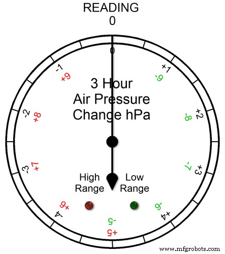
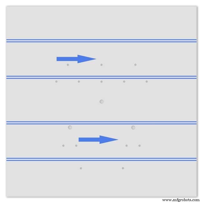
Das Animationsbild1. zeigt an, wie die LEDs leuchten, wenn die erweiterte Reichweite in Betrieb ist. Die rote LED zeigt an, wenn der Messwert +5 und mehr beträgt. Sie würden dann die rote Skalenbeschriftung lesen. Die grüne LED zeigt an, wenn der Messwert -5 und darunter beträgt. Sie würden dann die grüne Skalenbeschriftung lesen. Wenn der Messwert über den erweiterten Bereich hinausgeht, zB auf diesem Zifferblatt über +9 oder -9, leuchten beide LEDs, um dies anzuzeigen - siehe nächster Abschnitt.
Druckmesswerte über den erweiterten Bereich Abb.2 Wenn der Druckwert über dem erweiterten Bereich + oder - liegt, leuchten beide LEDs auf, um Sie zu warnen, dass extreme Messwerte oder Änderungen stattgefunden haben. Die Zifferblätter zeigen tatsächlich immer noch die Messwerte an, zB auf dem 3-Stunden-Zifferblatt, wenn der Messwert -10 war, dann würde das Zifferblatt auf 0 zeigen, wenn beide LEDs leuchten. Wenn die 3-Stunden-Anzeige -11 war, würde das Zifferblatt auf -1 zeigen, während beide LEDs leuchten. Sie addieren einfach 10 zum Messwert.
In der Animation unten beginnt die 3-Stunden-Druckdifferenz bei 0 und die Druckdifferenz nimmt ab. Bei -5 hPa leuchtet die grüne LED, um anzuzeigen, dass der negative erweiterte Bereich verwendet wird. Die Druckänderung nimmt weiter ab, bis sie -10 hPa erreicht. Dies ist jetzt über dem erweiterten Bereich, sodass die rote LED ebenfalls leuchtet. Der Druck sinkt dann wieder auf -11hPa und beide LEDs leuchten weiter. Die Druckänderung beginnt auf -10 hPa zu sinken und liegt wieder über dem erweiterten Bereich, sodass beide LEDs leuchten. Sobald die Druckänderung unter -10 sinkt, erlischt die rote LED und zeigt an, dass der erweiterte Bereich wieder verwendet wird.
Ich habe die erweiterte Reichweite in den Zifferblättern eingestellt, nachdem ich die Wetterextreme in Großbritannien überprüft hatte, und obwohl ich erwartet hatte, dass die erweiterten Reichweiten von 3 Stunden und 6 Stunden verwendet werden, dachte ich nicht, dass die erweiterte Reichweite jemals auf der Hauptbarometeranzeige verwendet werden würde.
Abb.3 Beim Prototyping des Barometers im Januar 2020 gab es einen Rekordwert von 1050 hPa. Im Süden Englands ging mein Hauptbarometer in den erweiterten Bereich, wobei der Zeiger auf der roten 1050 und die rote High Range LED leuchtete.
Schritt 4:LCD-Informationsanzeigen
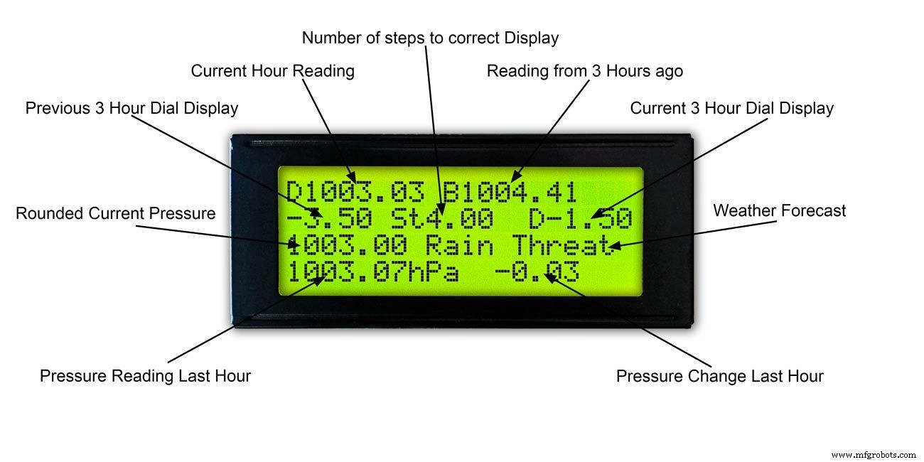
3 Stunden
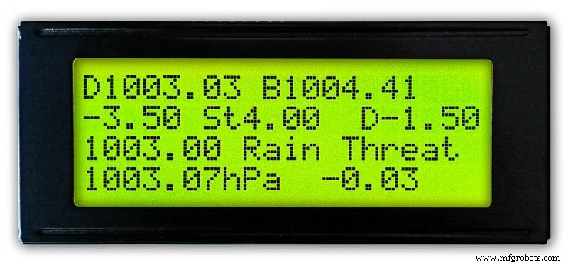
Abb. 1 &2 Dieses Display zeigt die 3-Stunden-Anzeige und Informationen auf dem 3-Stunden-Zifferblatt. Es zeigt auch die Wettervorhersage basierend auf der aktuellen und den letzten 3 Stunden an.
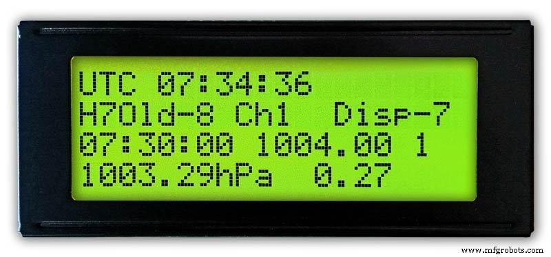
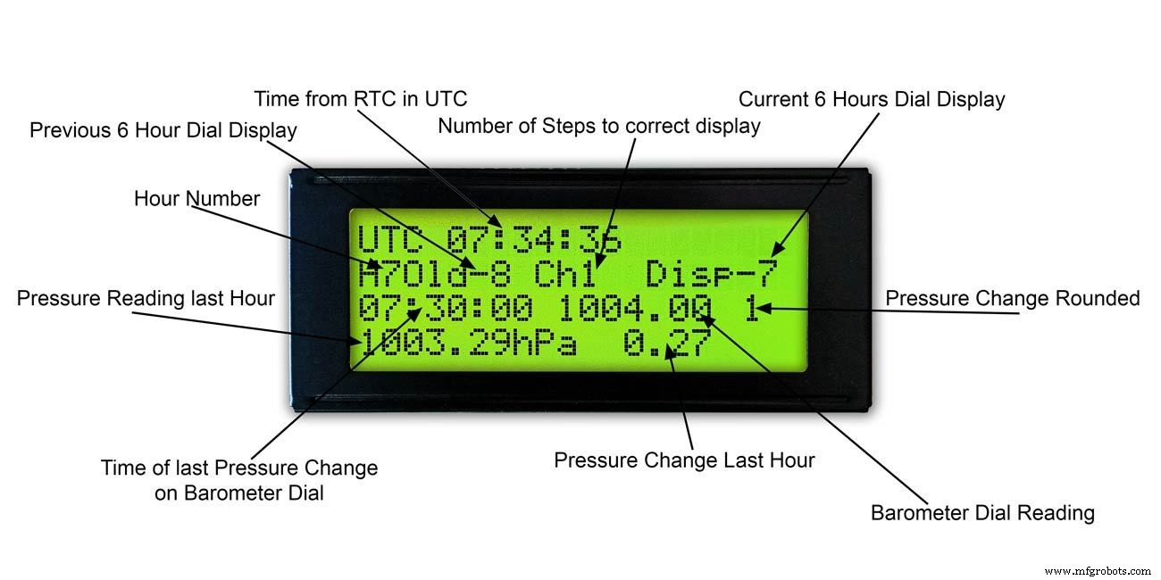
6 Stunden
Abb. 3 &4 Dieses Display zeigt die wichtigsten Barometeranzeigen und auch die 6-Stunden-Anzeigen an.
Schritt 5:Vorhersage des Wetters

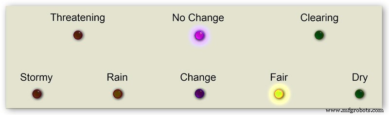


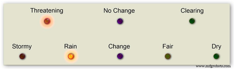
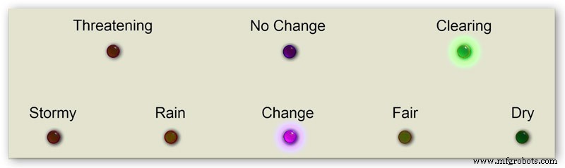
Die Wettervorhersage auf meinem Barometer verwendet 8 LEDs.
Anhand des aktuellen Luftdrucks und der Änderungsrate der letzten 3 Stunden wird das Wetter auf den LEDs vorhergesagt.
Animation 1 zeigt die verschiedenen Kombinationen von Vorhersage-LED-Kombinationen.
Ich habe eine Reihe von Wetterseiten besucht und die folgenden Informationen zur Vorhersage des Wetters mit einem Barometer gesammelt.
Das Wetter mit dem Barometer vorhersagen
Genauer gesagt kann ein Barometer mit Werten in hPa folgendermaßen interpretiert werden:
Wenn der Messwert über 1022 hPa liegt
Steigender oder konstanter Druck bedeutet anhaltend schönes Wetter. Langsam fallender Druck bedeutet schönes Wetter. Schnell fallender Druck bedeutet bewölkte und wärmere Bedingungen.
Wenn er zwischen 1009 und 1022 hPa liegt
Ein steigender oder konstanter Druck bedeutet, dass die gegenwärtigen Bedingungen anhalten. Ein langsam fallender Druck bedeutet eine geringe Änderung des Wetters. Ein schnell fallender Druck bedeutet, dass Regen wahrscheinlich ist oder Schnee, wenn es kalt genug ist.
Wenn der Messwert unter 1009 hPa liegt
Steigender oder stetiger Druck weist auf eine Aufhellung und kühleres Wetter hin. Langsam fallender Druck weist auf Regen hin.Schnell fallender Druck weist auf einen bevorstehenden Sturm hin.
Die Verwendung der Informationen über meinem Barometer wendet die folgende Logik an, um das Wetter vorherzusagen.
Die Logik wird in der folgenden Reihenfolge angewendet, wobei die resultierenden LEDs leuchten.
Abb.2 Luftdruck <1009 hPa
Steigender oder konstanter Druck weist auf Lichtung und kühleres Wetter hin
Luftdruck <1009.00 und 3 Stunden Änderung>=0
Abb.3 Luftdruck <1009 hPa
Langsam fallender Druck weist auf Regen hin
Luftdruck <1009,00 und 3-Stunden-Wechsel <0 und 3-Stunden-Wechsel>=-1,5
Abb.4 Luftdruck <1009 hPa
Ein schnell fallender Druck deutet auf einen bevorstehenden Sturm hin.
Luftdruck <1009.00 und 3-Stunden-Änderung <-1.5
Abb.5 Luftdruck liegt zwischen 1009 und 1022 hPa
Steigender oder stetiger Druck bedeutet, dass die gegenwärtigen Bedingungen anhalten.
Langsam fallender Druck bedeutet wenig Wetteränderung.
Luftdruck>=1009,00 und Luftdruck <=1022,00 und 3-Stunden-Wechsel>=-1,5 und 3-Stunden-Wechsel <=1,5
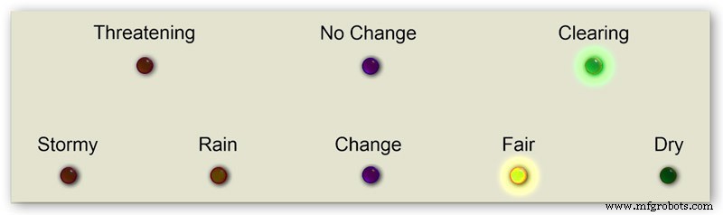
Abb.6 Luftdruck liegt zwischen 1009 und 1022 hPa
Schnell steigender Luftdruck bedeutet, dass das Wetter klarer wird
Luftdruck>=1009,00 und Luftdruck <=1022,00 und 3-Stunden-Änderung> 1,5
Abb.7 Luftdruck liegt zwischen 1009 und 1022 hPa
Schnell fallender Druck bedeutet, dass Regen wahrscheinlich ist oder Schnee, wenn es kalt genug ist.
Luftdruck>=1009.00 und Luftdruck <=1022.00 und 3-Stunden-Änderung <-1.5
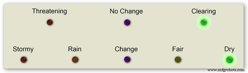
Abb.8 Luftdruck über 1022 hPa
Steigender oder konstanter Druck bedeutet trockenes Wetter.
Luftdruck> 1022,00 und 3 Stunden Änderung>=0
Abb.9 Luftdruck über 1022 hPa
Langsam fallender Druck bedeutet schönes Wetter.
Luftdruck> 1022,00 und 3-Stunden-Wechsel <0 und 3-Stunden-Wechsel>=-1,5
Abb.10 Luftdruck über 1022 hPa
Schnell fallender Druck bedeutet Veränderung
Luftdruck> 1022,00 &&3-Stunden-Änderung <-1,5
Schritt 6:Start des Barometers
Beim ersten Einschalten wird ein LED-Test durchgeführt.
Sobald dies abgeschlossen ist, gehen die Zeiger auf ihre Anfangseinstellungen zurück und können kalibriert werden.
Schritt 7:Erste Starteinstellungen RTC
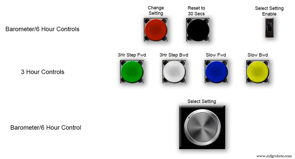


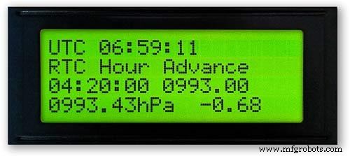
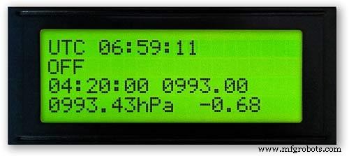
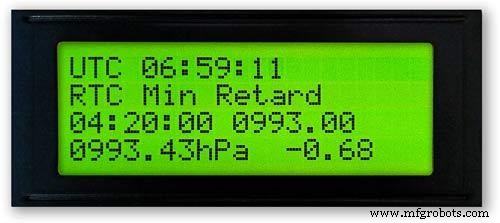

Abb.1 Beim ersten Einschalten muss das Barometer mit den Bedienelementen auf dem Vero Board eingerichtet werden.
RTC
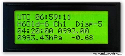
Abb.2 Die RTC muss auf die richtige Zeit eingestellt werden. Ich stelle sie auf UTC ein und kümmere mich nicht um die Umstellung auf Sommerzeit. Notieren Sie sich vor dem Einstellen der Uhrzeit den Wert "Disp" in diesem Fall -5. Dies ist der Wert des 6-Stunden-Zeigers und wird später im Setup benötigt. Schieben Sie den Schalter „Select Setting Enable“ auf die Position „On“. Die Anzeige ändert sich nicht.
Abb.3 Drehen Sie den "Select Setting"-Knopf langsam im Uhrzeigersinn und die zweite Zeile des Haupt-LCD-Displays ändert sich.
Stoppen, wenn das Display „RTC Hour Retard“ anzeigt Wenn Sie die RTC-Stunden verzögern möchten, drücken Sie die rote Taste „Change Setting“. Mit einem einzigen Klick werden die Stunden rückwärts geschaltet. Durch mehrere Klicks wird die Anzahl der gedrückten Klicks zurückgesetzt, es dauert jedoch eine Sekunde, bis die Echtzeituhr aktualisiert ist.
Abb.4 Durch weiteres Drehen des "Select Setting"-Knopfes ändert sich die Anzeige auf "RTC Hour Advance"
Wenn Sie die RTC-Stunden vorrücken möchten, drücken Sie die rote Taste "Einstellung ändern". Mit einem einzigen Klick werden die Stunden vorwärts geschaltet. Mehrere Klicks erhöhen die Anzahl der gedrückten Klicks, es dauert jedoch eine Sekunde, bis die Echtzeituhr aktualisiert wird.
Abb.5 Durch weiteres Drehen des "Select Setting"-Knopfes ändert sich die Anzeige auf "RTC Min Retard"
Wenn Sie die RTC-Minuten verzögern möchten, drücken Sie die rote Taste "Einstellung ändern". Mit einem einzigen Klick werden die Minuten rückwärts geschaltet. Durch mehrere Klicks wird die Anzahl der gedrückten Klicks zurückgesetzt, es dauert jedoch eine Sekunde, bis die Echtzeituhr aktualisiert ist.
Abb.6 Durch weiteres Drehen des "Select Setting"-Knopfes ändert sich die Anzeige auf "RTC Min Advance"
Wenn Sie die RTC-Minuten vorrücken möchten, drücken Sie die rote Taste "Einstellung ändern". Mit einem einzigen Klick werden die Minuten vorwärts geschaltet. Bei mehreren Klicks wird die Anzahl der gedrückten Klicks erhöht, es dauert jedoch eine Sekunde, bis die Echtzeituhr aktualisiert wird.
Abb.7 Wenn Sie die RTC-Einstellung oder eine andere Einstellung abgeschlossen haben, drehen Sie den "Select Setting"-Knopf ganz gegen den Uhrzeigersinn zurück, bis das Display "Off" anzeigt
Schieben Sie den Schalter "Select Setting Enable" auf die Position "Off".
Notiz. Die Sekunden können jederzeit durch Drücken der schwarzen "Reset to 30 Sekunden"-Taste auf 30 Sekunden synchronisiert werden. Die Zeit wird nun auf der RTC gespeichert, wenn der Strom ausgeschaltet wird.
Schritt 8:Erste Starteinstellungen 6-Stunden-Zeiger


Einstellen des 6-Stunden-Zeigers
Abb.1 Sobald die RTC eingestellt ist, müssen das Barometer und die 6-Stunden-Luftdruckzeiger eingestellt werden.
Schieben Sie den Schalter „Select Setting Enable“ auf die Position „On“. Die Anzeige ändert sich nicht.
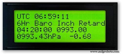
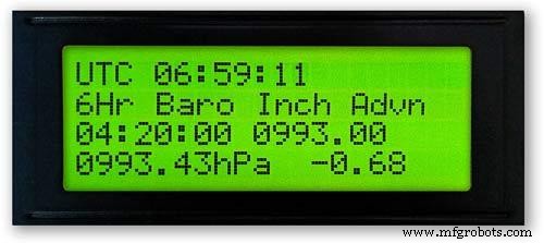
Drehen Sie den "Select Setting"-Knopf langsam im Uhrzeigersinn, bis "6Hr Baro Inch Retard" angezeigt wird.
Beim allerersten Einschalten muss der 6-Stunden-Zeiger auf die nächste Ziffer kalibriert werden.
Befindet sich die nächste Ziffer hinter der Hand, drücken Sie die rote Taste „Einstellung ändern“. Mit einem einzigen Klick wird die Hand Schritt für Schritt rückwärts bewegt. Wenn Sie die Taste gedrückt halten, bewegt sich die Hand wiederholt rückwärts. Sobald sich der Zeiger genau auf einer Ziffer befindet, lassen Sie den Knopf los.
Abb.2 Wenn die nächste Ziffer vor der Hand liegt oder wenn Sie die Hand mit den oben genannten Schritten zu sehr verzögert haben, drehen Sie den "Select Setting"-Knopf im Uhrzeigersinn, bis "6Hr Baro Inch Advn" angezeigt wird.
Drücken Sie die rote Taste „Einstellung ändern“. Mit einem einzigen Klick bewegt sich die Hand Schritt für Schritt vorwärts. Wenn Sie die Taste gedrückt halten, bewegt sich die Hand wiederholt vorwärts. Sobald sich der Zeiger genau auf einer Ziffer befindet, lassen Sie den Knopf los.
Abb.3 Nachdem der 6-Stundenzeiger genau auf eine Ziffer eingestellt wurde, muss der Stundenzeiger auf den richtigen Wert eingestellt werden.
Vor dem Einstellen der Echtzeituhr haben Sie sich diese Nummer -5 notiert.
Abb.4 Wenn der Zeiger der 6-Stunden-Anzeige zu weit fortgeschritten ist.
Drehen Sie den "Select Setting"-Knopf im Uhrzeigersinn, bis "6Hr Baro Retard" angezeigt wird. Drücken Sie die rote Taste „Einstellung ändern“ und lassen Sie sie wieder los. Diese Schwelle stellt den 6-Stunden-Zeiger um eine ganze Einheit zurück. Stoppen Sie, wenn der 6-Stunden-Zeiger Ihre notierte Zahl erreicht.
Abb.5 Wenn der Zeiger der 6-Stunden-Anzeige verzögert ist.
Drehen Sie den "Select Setting"-Knopf im Uhrzeigersinn, bis "6Hr Baro Advance" angezeigt wird. Drücken Sie die rote Taste „Einstellung ändern“ und lassen Sie sie wieder los. Diese Schwelle stellt den 6-Stunden-Zeiger um eine ganze Einheit vor. Stoppen Sie, wenn der 6-Stunden-Zeiger Ihre notierte Zahl erreicht.
Abb.6 Beachten Sie, dass die 6-Stunden-Anzeige 8 Stunden braucht, um richtig angezeigt zu werden, da die Messwerte über diesen Zeitraum im Speicher gespeichert werden müssen.
Sie können vor dem Laden jederzeit die vorherigen Luftdruckwerte in den Code einfügen, wenn Sie die 6-Stunden-Anzeige benötigen, um vom Start an zu funktionieren.
Der Code wandelt die Stunden in eine H-Zahl um, wie oben angezeigt H =6. In der Codezeile 128 bedeutet H6, dass die aktuelle Stundenanzeige unter Stunde steht6 die vorherige Anzeige in Stunde7 die Anzeige davor in Stunde0 usw.
int Stunde0 =1015;
int Stunde1 =1016
;int Stunde2 =1015;
int Stunde3 =1016;
int Stunde4 =1016
;int Stunde5 =1016;
int Stunde6 =1012;
int Stunde7 =1013;
Sie sollten Ihre lokalen Messwerte aus dem Internet abrufen können.
Ich habe von meiner Wetterstation aus eine Seite eingerichtet, damit ich dies beim Bau des Barometers überprüfen kann.
Klicken Sie auf diesen Link, um die stündlichen Änderungen in Kenley Surrey UK anzuzeigen.
Schritt 9:Erste Starteinstellungen Haupt-Barometerzeiger


Einstellen des Hauptbarometerzeigers
Abb.1 Jetzt ist die 6-Stunden-Anzeige korrekt, der Hauptbarometerzeiger muss auf den gerundeten Meeresspiegeldruck in der 3. Reihe unten auf dem Haupt-LCD eingestellt werden.
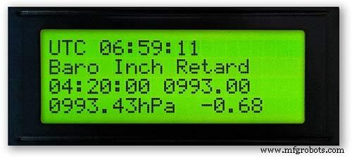
Beim ersten Einschalten muss der Hauptbarometerzeiger auf die nächste Ziffer kalibriert werden. Drehen Sie den "Select Setting"-Knopf im Uhrzeigersinn, bis "Baro Inch Retard" angezeigt wird.
Befindet sich die nächste Ziffer hinter der Hand, drücken Sie die rote Taste „Einstellung ändern“. Mit einem einzigen Klick wird die Hand Schritt für Schritt rückwärts bewegt. Wenn Sie die Taste gedrückt halten, bewegt sich die Hand wiederholt rückwärts. Sobald sich der Zeiger genau auf einer Ziffer befindet, lassen Sie den Knopf los.
Abb.2 Wenn die nächste Ziffer vor der Hand liegt oder wenn Sie die Hand mit den oben genannten Schritten zu stark verzögert haben, drehen Sie den "Select Setting"-Knopf im Uhrzeigersinn, bis "Baro Inch Advn" angezeigt wird.
Drücken Sie die rote Schaltfläche "Einstellung ändern".
Mit einem einzigen Klick bewegt sich die Hand Schritt für Schritt vorwärts. Wenn Sie die Taste gedrückt halten, bewegt sich der Zeiger wiederholt vorwärts. Sobald sich der Zeiger genau auf einer Ziffer befindet, lassen Sie die Taste los.
Abb.3 Wenn der Hauptbarometerzeiger zu weit vorgerückt ist.
Drehen Sie den "Select Setting"-Knopf im Uhrzeigersinn, bis "Barometer Retard" angezeigt wird.
Drücken Sie die rote Taste "Einstellung ändern" und lassen Sie sie wieder los.
Dadurch wird der Hauptbarometerzeiger um eine ganze Einheit zurückgestellt. Stoppen Sie, wenn der Stundenzeiger Ihren angezeigten gerundeten Meeresspiegeldruck erreicht.
Abb.4 Wenn der Hauptbarometerzeiger im Vergleich zum angezeigten gerundeten Meeresspiegeldruck verzögert ist.
Drehen Sie den "Select Setting"-Knopf im Uhrzeigersinn, bis "Barometer Advance" angezeigt wird.
Drücken Sie die rote Taste "Einstellung ändern" und lassen Sie sie wieder los.
Dadurch wird der Hauptbarometerzeiger um eine ganze Einheit nach vorne bewegt. Stoppen Sie, wenn die Hand Ihren angezeigten gerundeten Meeresspiegeldruck erreicht.
Schritt 10:Erste Starteinstellungen 3-Stunden-Zeiger


Einstellen des 3-Stunden-Zeigers.
Oic.1 Die Einstellung des 3-Stunden-Zeigers erfolgt über die vier Knöpfe Grün, Weiß, Blau und Gelb auf der Vero-Platine.
Beim ersten Einschalten muss der 3-Stunden-Zeiger auf die nächste Einheit oder halbe Einheit kalibriert werden.
Abb.2 Wenn der dem 3-Stunden-Zeiger am nächsten liegende Einheitswert vor dem 3-Stunden-Zeiger liegt, drücken Sie die gelbe Taste "Slow Bwd", um den Zeiger rückwärts zu bewegen. Wenn Sie die Taste gedrückt halten, wird die Hand wiederholt rückwärts bewegt.
Wenn der nächste Einheitswert des 3-Stunden-Zeigers hinter dem 3-Stunden-Zeiger liegt, drücken Sie die blaue Taste "Slow Fwd", um den Zeiger vorwärts zu bewegen. Wenn Sie die Taste gedrückt halten, bewegt sich die Hand wiederholt vorwärts.
Sobald sich der 3-Stunden-Zeiger genau auf einer Einheit/halben Einheit befindet, kann der Zeiger auf dem 3-Stunden-LCD-Display auf den Wert "D" eingestellt werden.
Wenn der Zeiger vor dem Wert "D" steht, drücken Sie die weiße Taste "3Hr Step Bwd", um den 3-Stunden-Zeiger in halben Einheiten rückwärts zu bewegen.
Wenn der Zeiger weniger als den Wert "D" hat, drücken Sie die grüne Taste "3Hr Step Fwd", um den 3-Stunden-Zeiger in halben Einheiten vorwärts zu bewegen.
Beachten Sie, dass es 4 Stunden dauert, bis die 3-Stunden-Anzeige korrekt angezeigt wird, da die Messwerte über diesen Zeitraum im Speicher gespeichert werden müssen.
Sie können vor dem Laden jederzeit die vorherigen Luftdruckwerte in den Code einfügen, wenn Sie die Vorhersage und die 3-Stunden-Anzeige benötigen, um vom Start an zu funktionieren.
3-Stunden-Anzeigecode in Zeile 124
float hour0 ist die aktuelle Stunde
float Stunde1 ist die vorherige Stunde usw usw.
Float Stunde0 =1036.00;
Float Stunde1 =1036.00;
Float Stunde2 =1036.00;
Float Stunde3 =1036.00;
Float Stunde4 =1036.00;
Sie sollten Ihre lokalen Messwerte aus dem Internet abrufen können.
Schritt 11:Module/Komponenten

Module
Wo möglich verwendet dieses Projekt vorgefertigte Module, um Bau- und Entwurfszeit zu sparen.
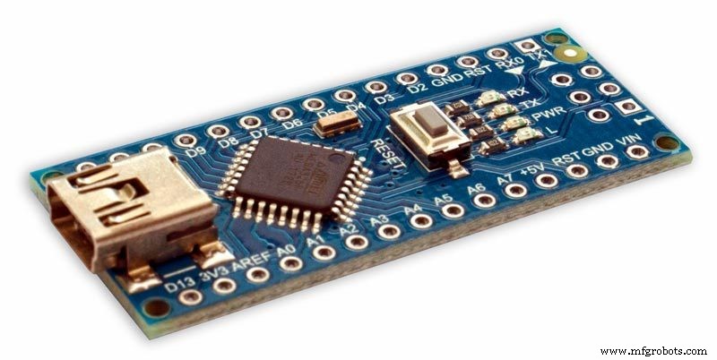
Mikroprozessoren
Dieses Projekt verwendet 2 Mikroprozessoren, einen Atmega 328 (UNO) pic.1 und einen Arduino Nano pic.2. Ich habe diese Kombination verwendet, da ich bereits eine 328 aus einem anderen Projekt gebaut hatte und aufgrund des begrenzten Platzes auf dem Vero Board auch den Nano hinzugefügt hatte.
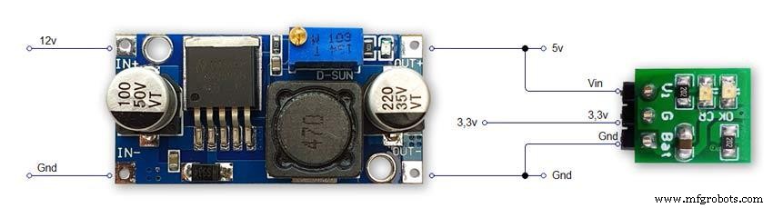
Kraft
Das Barometer verbraucht etwa 65 mA und dies wird ein wenig erhöht, wenn jeder Motor alle 10 Minuten bis und Stunde für einen Bruchteil einer Sekunde weiterschreitet
AMS117 Bild 3
Das Modul in diesem Projekt ist 3,3 V und wird verwendet, um das BMP180-Modul mit Strom zu versorgen.
Die einstellbaren und festen Spannungsregler der Serie AMS1117 sind so konzipiert, dass sie einen Ausgangsstrom von bis zu 1 A bereitstellen und bis zu 1 V Eingangs-Ausgangs-Differenz arbeiten. Die Dropout-Spannung des Geräts wird mit maximal 1,3 V garantiert und nimmt bei niedrigeren Lastströmen ab. Die On-Chip-Trimmung passt die Referenzspannung auf 1,5% an. Die Strombegrenzung wird eingestellt, um die Belastung unter Überlastbedingungen sowohl des Reglers als auch der Stromquellenschaltung zu minimieren. Das Modul in diesem Projekt ist 3,3 V und wird verwendet, um das BMP180-Modul mit Strom zu versorgen.
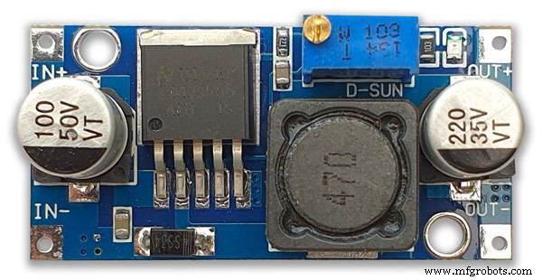
LM2596 Buck DC to DC Converter 3.0-40V to 1.5-35V pic.4Dieses Modul wandelt den 12V Eingang in 5V um
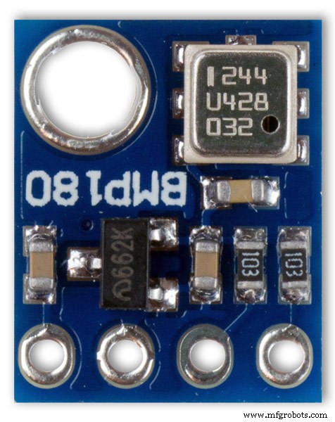
BMP180 Drucksensormodul 2 aus Bild 5 Der BMP180 Breakout ist ein Luftdrucksensor mit einer I2C ("Wire") Schnittstelle. Luftdrucksensoren messen den absoluten Druck der sie umgebenden Luft. Dieser Druck variiert sowohl mit dem Wetter als auch mit der Höhe. Je nachdem, wie Sie die Daten interpretieren, können Sie Wetteränderungen überwachen, die Höhe messen oder andere Aufgaben ausführen, die eine genaue Druckmessung erfordern.
Verbinden Sie die Pins +, -, CL und DA mit Ihrem Arduino.
CL geht zu SCL und DA geht zu SDA.
WICHTIG:Schließen Sie die Stromstifte (+ und -) NUR an eine 3,3 V-Versorgung an. Höhere Spannungen beschädigen das Teil dauerhaft. Beachten Sie, dass es sicher ist, die I2C-Pins (DA und CL) an einen I2C-Port eines 5 V-Mikroprozessors anzuschließen, da I2C Open-Drain-Treiber verwendet.
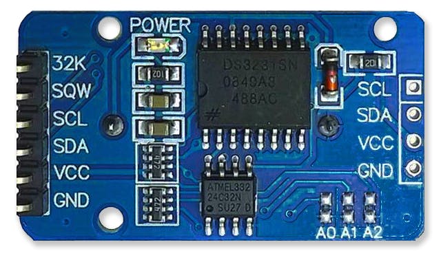
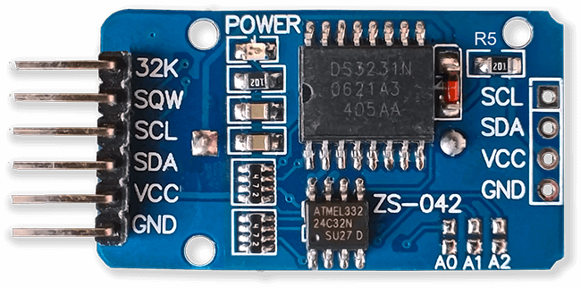
RTC-Echtzeituhr Bild 6
Dieses Brometer verwendet ein DS3231 AT24C32 I2C Precision Real Time Clock Module.
Dieses Modul dient hauptsächlich der Zeitmessung, liefert aber auch Zeitstempel auf dem LCD-Display. Die Uhrzeit ist auf UTC eingestellt und wird nicht für die Sommerzeit geändert. Das Modul wird mit einem Lithium-Ionen-Akku geliefert, siehe Abbildung oben. Ich verwende eine nicht wiederaufladbare Batterie, daher habe ich den Widerstand R5 aus dem Modul entfernt, siehe Abschnitt RTC-Modifikation für Details.
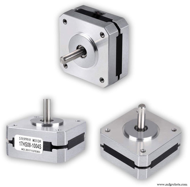
Schrittmotoren 3 Stück Das Barometer verwendet 3 Nema 17-Schrittmotoren 1A, 13N.cm Haltemoment, 4-Leiter, 1,8° Ich habe 1,8°-Motoren verwendet, da die Schritte 200 Mal genau in 360° passen. Sie können Nema 8-Motoren verwenden, wenn Sie möchten, verwenden Sie jedoch keine 28BYJ-48-5V-Motoren, da sie nicht den erforderlichen Schrittwinkel von 1,8 ° haben.
Der Schrittwinkel von 1,8° ist erforderlich, da er sich für meine Barometer-Zifferblätter genau in 360° teilt.
LCD zeigt 2 aus
Ich habe 2 20x4 LCD-Displays verwendet, eines für das Barometer, die Uhr und die 6-Stunden-Anzeige und das andere für die 3-Stunden-Anzeige und die Vorhersage.
Schritt 12:Module/Komponenten A4988 Schrittmotortreiber
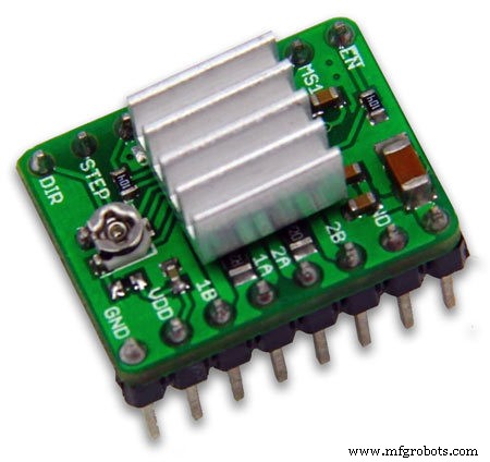
A4988 Mikroschritt-Bipolar-Schrittmotortreiber 3 aus
Wichtig diesen Abschnitt sorgfältig lesen
Mein Barometer ist auf 1/16-Schritt-Rotation eingestellt und der Code wird entsprechend angepasst.
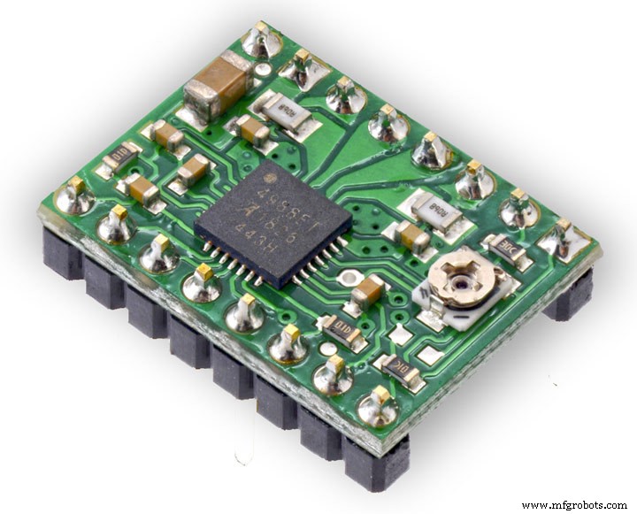
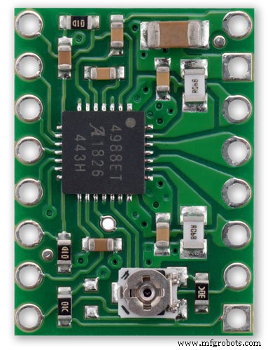
A4988 Mikroschritt-Bipolar-Schrittmotortreiber Bild 1 mit und Bild 2 ohne Kühlkörper
Dieses Breakout-Board für den bipolaren Mikroschritt-Schrittmotortreiber A4988 von Allegro bietet eine einstellbare Strombegrenzung, einen Überstrom- und Übertemperaturschutz sowie fünf verschiedene Mikroschritt-Auflösungen (bis zu 1/16-Schritt).
Er arbeitet von 8 V bis 35 V und kann bis zu ca. 1 A pro Phase ohne Kühlkörper oder forcierten Luftstrom liefern (er ist für 2 A pro Spule mit ausreichender zusätzlicher Kühlung ausgelegt).
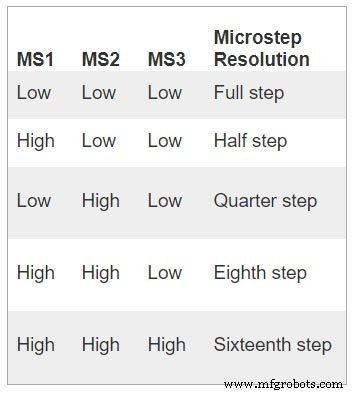
Hier sind einige der wichtigsten Funktionen des Treibers:Einfache Schritt- und Richtungssteuerungsschnittstelle Fünf verschiedene Schrittauflösungen:Vollschritt, Halbschritt, Viertelschritt, Achtelschritt und Sechzehntelschritt Mit der einstellbaren Stromsteuerung können Sie die maximale Stromabgabe einstellen mit einem Potentiometer, mit dem Sie Spannungen über der Nennspannung Ihres Schrittmotors verwenden können, um höhere Schrittraten zu erreichen Intelligente Chopping-Steuerung, die automatisch den richtigen Stromabklingmodus (schneller Abfall oder langsamer Abfall) auswählt Übertemperatur-Thermoabschaltung, Unterspannungssperre und Querstromschutz Erdschluss- und Lastkurzschlussschutz
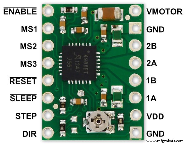
Stromanschlüsse Der Treiber benötigt eine Logikversorgungsspannung (3 – 5,5 V) über die VDD- und GND-Pins und eine Motorversorgungsspannung (8 – 35 V) über VMOT und GND. Diese Netzteile sollten über geeignete Entkopplungskondensatoren in der Nähe der Platine verfügen und die erwarteten Ströme liefern können (Spitzen bis zu 4 A für die Motorversorgung).
Warnung:Dieses Trägerboard verwendet Keramikkondensatoren mit niedrigem ESR, was es anfällig für destruktive LC-Spannungsspitzen macht, insbesondere bei Verwendung von Stromkabeln, die länger als ein paar Zoll sind. Unter den richtigen Bedingungen können diese Spitzen die maximale Nennspannung von 35 V für den A4988 überschreiten und die Platine dauerhaft beschädigen, selbst wenn die Motorversorgungsspannung nur 12 V beträgt. Eine Möglichkeit, den Treiber vor . zu schützen Bei solchen Spitzen muss ein großer (mindestens 47 µF) Elektrolytkondensator über die Motorleistung (VMOT) und irgendwo in der Nähe der Platine geerdet werden.
Motoranschlüsse
Vier-, sechs- und achtdrahtige Schrittmotoren können vom A4988 angesteuert werden, wenn sie richtig angeschlossen sind. Warning:Connecting or disconnecting a stepper motor while the driver is powered can destroy the driver. (More generally, rewiring anything while it is powered is asking for trouble.)
Step (and microstep) size
see table pic. 3Stepper motors typically have a step size specification (e.g. 1.8° or 200 steps per revolution), which applies to full steps. A microstepping driver such as the A4988 allows higher resolutions by allowing intermediate step locations, which are achieved by energizing the coils with intermediate current levels. For instance, driving a motor in quarter-step mode will give the 200-step-per-revolution motor 800 microsteps per revolution by using four different current levels.
The resolution (step size) selector inputs (MS1, MS2, and MS3) enable selection from the five step resolutions according to the table below. MS1 and MS3 have internal 100kΩ pull-down resistors and MS2 has an internal 50kΩ pull-down resistor, so leaving these three microstep selection pins disconnected results in full-step mode. For the microstep modes to function correctly, the current limit must be set low enough (see below) so that current limiting gets engaged. Otherwise, the intermediate current levels will not be correctly maintained, and the motor will skip microsteps.
Control inputs
pics 4 &5Each pulse to the STEP input corresponds to one microstep of the stepper motor in the direction selected by the DIR pin. Note that the STEP and DIR pins are not pulled to any particular voltage internally, so you should not leave either of these pins floating in your application.
If you just want rotation in a single direction, you can tie DIR directly to VCC or GND. The chip has three different inputs for controlling its many power states:RST, SLP, and EN. For details about these power states, see the datasheet.
Please note that the RST pin is floating; if you are not using the pin, you can connect it to the adjacent SLP pin on the PCB to bring it high and enable the board.
Current LImiting Before connecting the motor we should adjust the current limiting of the driver so that we are sure that the current is within the current limits of the motor. We can do that by adjusting the reference voltage using the potentiometer on the module to set the VRef.
See details on the video link pic. 6
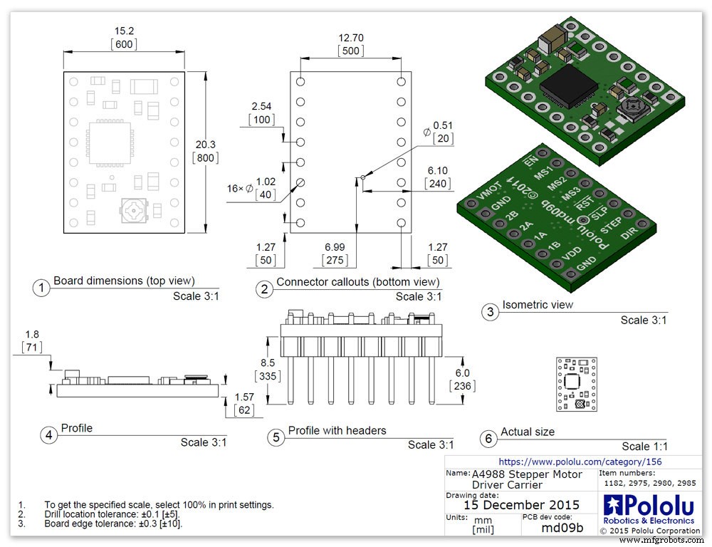
Manufacturers Drawing sheet pic.7
Step 13:Construction Prototyping
The circuit was prototyped using a hardboard dial with holes drilled for the motor spindles and LEDs.
Various dial designs were then printed on normal paper and Sellotaped over the top. The LED wiring loom was made with the LEDs in position on the temporary dial.
If you are using the round dial design this will allow you to check if the board etc will be mounted on the dial or in the back box.
Step 14:Construction RTC Modification
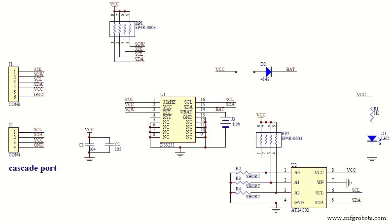
The module comes supplied with a Lithium-Ion rechargeable battery see diagram pic. 2.
I use a non rechargeable battery (I am not happy with the circuit design with a lithium-iron battery and associated fire risk) of the so have removed resistor R5 from the module as below. This stops any charge current to the battery.
Pic.3 shows the module without the resistor (just break it off) and pic.4 the modified circuit.
Step 15:Construction Mounting Modules &Boards
On the modern square dial design all the modules and boards are mounted on the dial. The classic round dial desgn will need some parts mounted in the back box as there is less space on the dial.
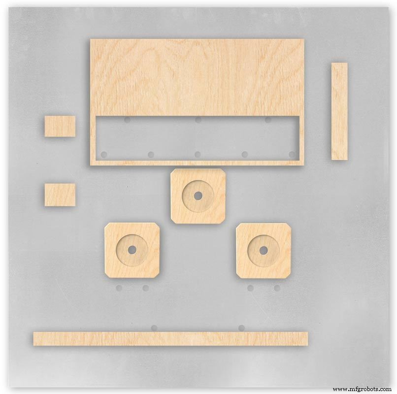
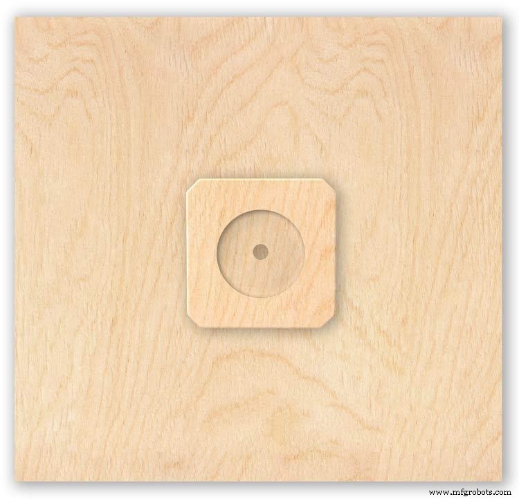
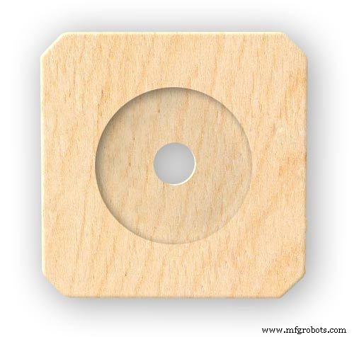
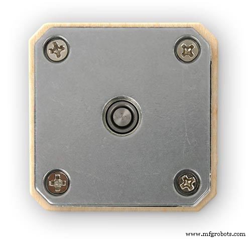
Motors are hot melt glued to wooden mounting blocks pic.1&2. The wooded blocks are cut fron a sheet of plywood pic.3. The mounting blocks depths are set to allow the correct protrusion of the spindles through the dial. I have hot melt glued the blocls to the dial.
The Vero Boards and LCD displays are also screwed to wooden blocks which have been glued to the dial using impact adhesive.
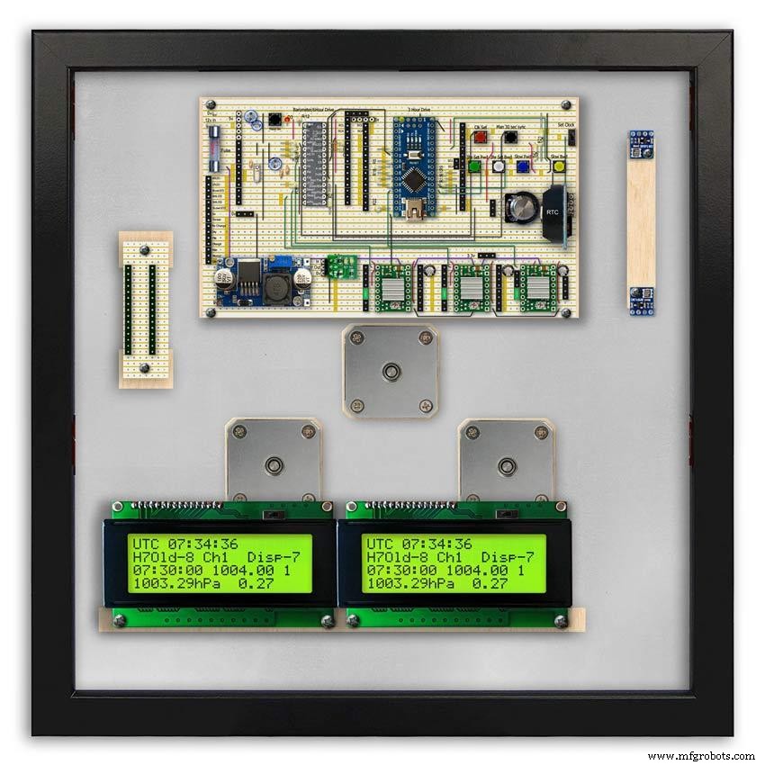
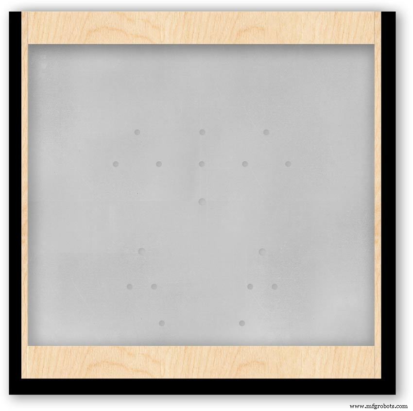
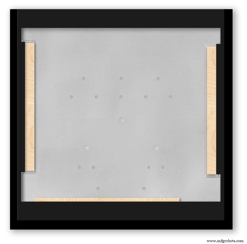
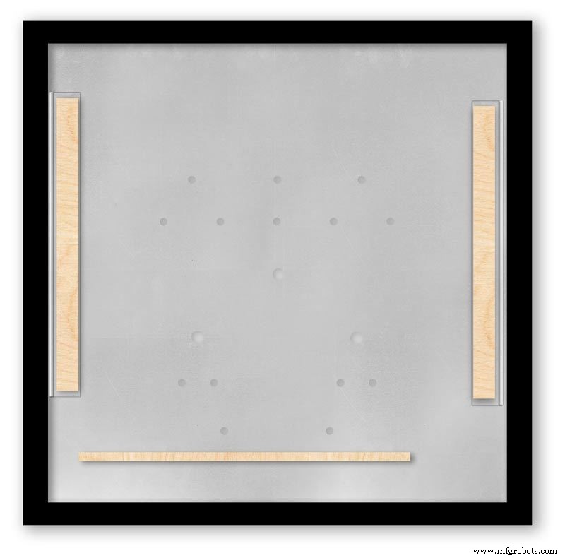
Pic.4 shows the front view with a transparent dial showing mounting locations.
Pic. 5 shows the same but the rear view.
Pic.6 shows the wooden mounting blocks locations and layout.
Pic.7 shows the modules and motors mounted on the blocks.
Step 16:Construction LED Fixing

The 3mm LEDs are mounted so they just show above the surface of the dial pic.1.
3mm holes are drilled and hot melt glue holds them in place.
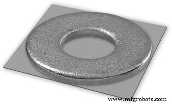
To get a uniform depth I made a jig using a washer and piece of card glued to it pic.2.When fixing the LEDs the jig is pressed against the dial with the depth of the washer setting the protrusion of the LED through the dial.
Step 17:Construction Classic Style English Dial Clock Case
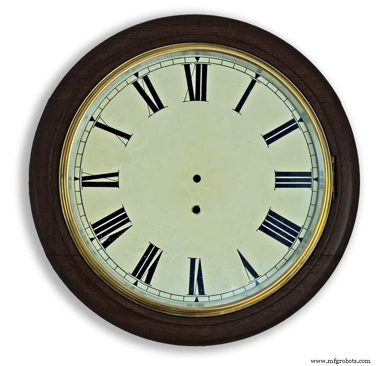
The classic 12" Dial Clock case can be purchased from Ebay as "case only" pic.1.
Various styles are available this one is oak and has a dial surround that hinges away from the back box pic.2.
This makes for a very easy build as all the hard work has been done. The dial is mounted by 3 small wood screws hidden behind the brass dial bezel.
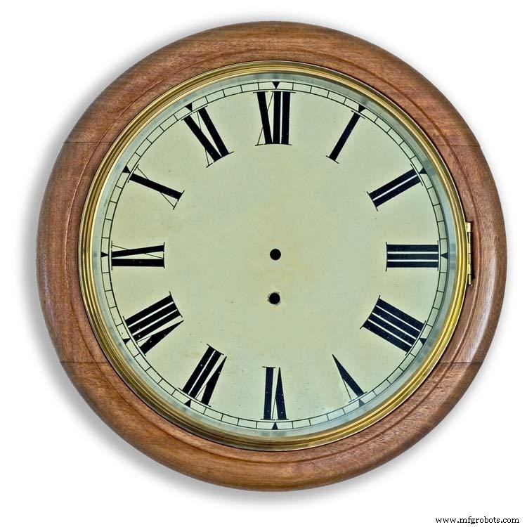
This dial surround has been stripped and bleached to bring out the original light colour of the wood pic.3.The dial was removed as it had a winding hole off center.
A new dial was cut from a sheet of alluminium pic.4.
Pic.5 side view of the Barometer showing the back box.
Pic.6 shows my regulator clock case with original curved back box, hinged dial bezel and pegged dial surround.
Many of these clock cases were held in place by four wooden pegs. If your case is constructed like this add a pair of hinges to one side and use the remaining two pegs to lock the dial surround in place.
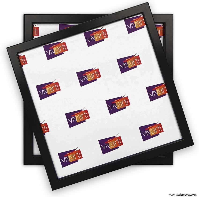
Step 18:Construction Modern Case


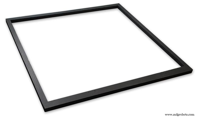
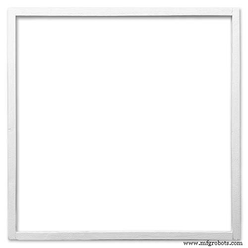
Picture Frame Version
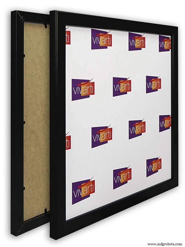
I have used two identical picture frames mounted back to back. These frames are 30cm x 30cm approx. 12"x12" pic.1.
pic.2 Frames are joined back to back.
pic.3 This gives a double depth frame.
pic.4 Rear side view showing wired boards and modules.
pic.5 The dial viewed through the rear frame.
pic.6 Rear half of the frame with all wiring in place.
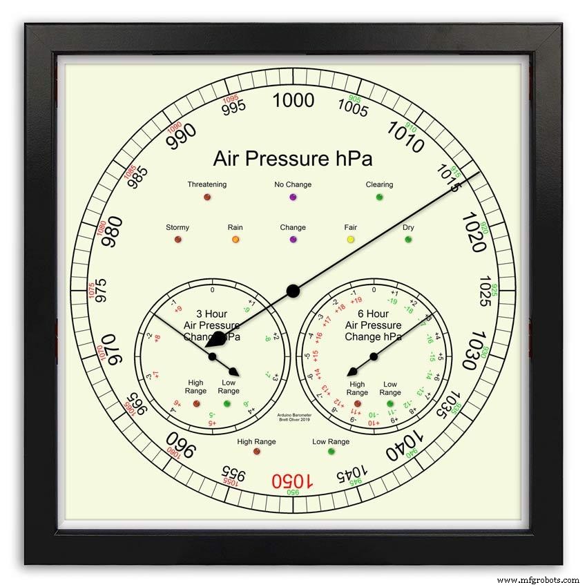
pic.7 The front of the dial now shows through the front half of the frame. Wooden bevels hide the space behind the front half of the frame.
Step 19:Construction Modern Case Backbox
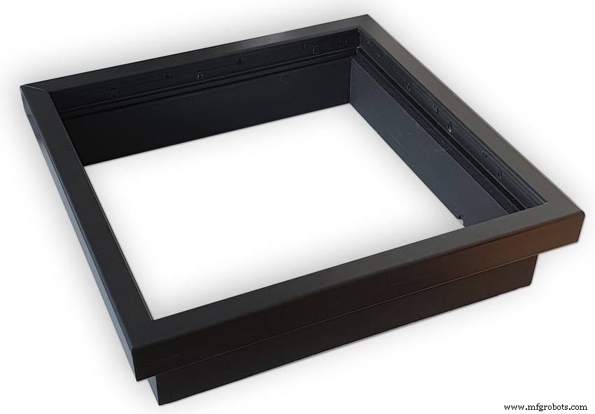
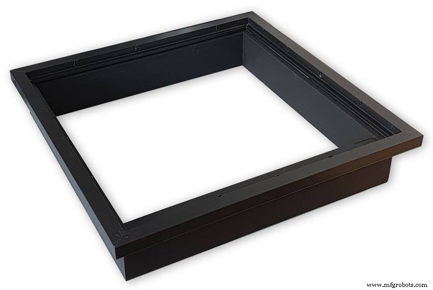


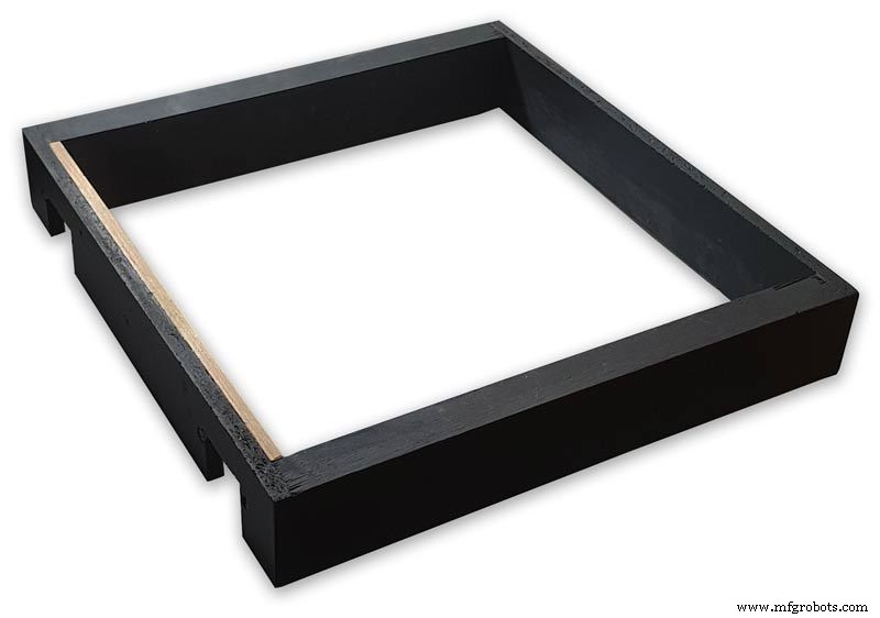
Back Box
Pic.1 The barometer is housed in a back box that is smaller than the dial frame on all side apart from the top. The fram overlap helps hide the back box and adds a shadow effect to the case on the wall.
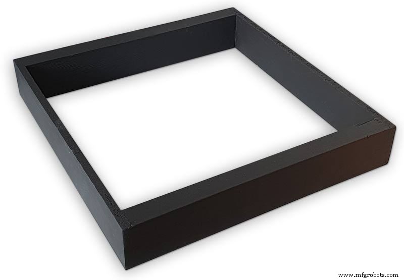
Pic.2 The back box is 50mm deep and is simply constructed of glued and screwed wood.
Pic.3 Rear view of back box in position behind rear dial frame showing the frame overlap.
Pic.4 The screw holes are filled then a coat of matt black is applied to the back box.
Pic.5 Back box with rear picture frame in place this holds the dial.Note the rear frame is placed upside down.
Pic.6 A spacer is cut the same size and depth as the recess of the picture frame.
Pic.7 The spacer is set under the dial.
Pic.8 This will raise the dial level with the top edge of the rear frame.
Pic.9 Back box with front picture frame in place on top of the rear frame.This frame holds the glass.
Step 20:Construction Modern Case Wall Mounting


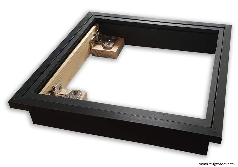
Mounting the Barometer
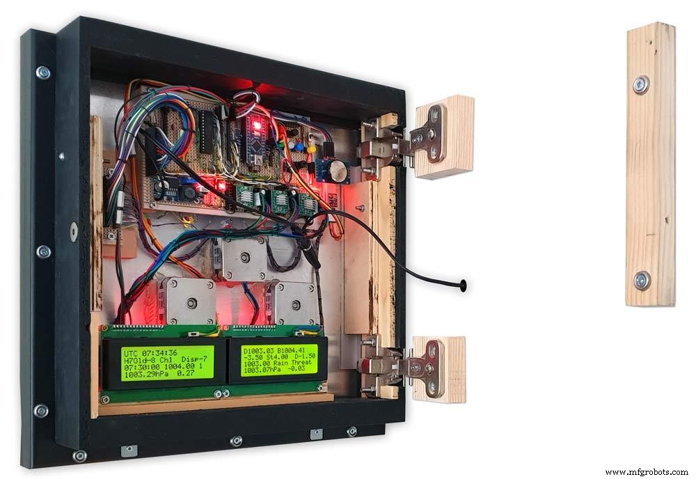
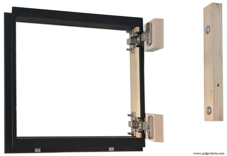
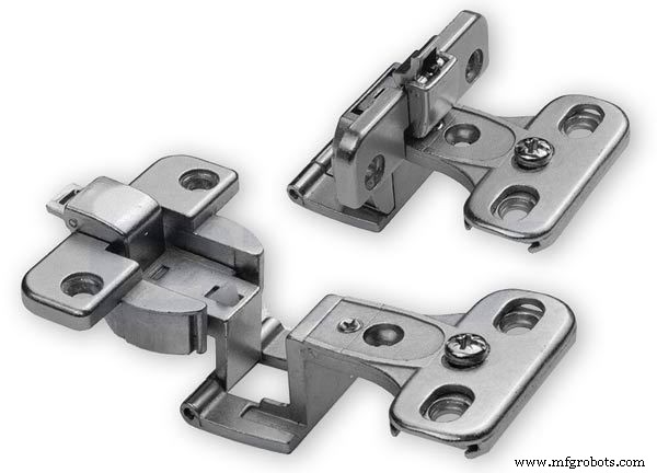
Pic.1 To allow access to the rear of the Barometer I have mounted it on a pair of GTV 270° inset hinges. The hinges are mounted on a block of wood fixed to the wall and allow the barometer to be swung out for access. The hinges also have a quick release function if the Barometer needs to be taken down for maintenance at any time. The hinge pivot is set back which also allows the top of the case to clear the wall when hinged out.
Pic.2 The hinges are mounted on wooden blocks screwed to the wall.
Pic.3 I have screwed and glued an extra piece of timber to the left hand side where the hinges will mount.This will add strength as all the weight of the clock will be on this side when the clock case is open. Two aluminium plates will cover the hinge holes.
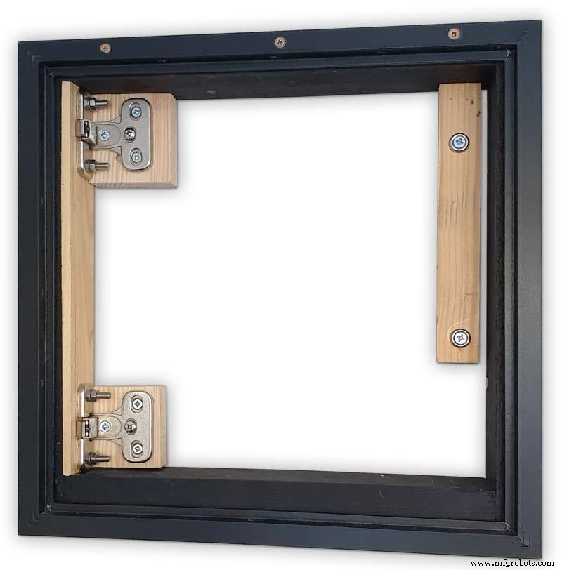
Pic.4 Hinge blocks in place. Note these are bolted through the case rather than screwed.
Pic.5 Back Box mounted on the wall. The fixing screws also hold the hinge to the wooden mounting blocks The wooden baton on the right is also fixed to the wall and supports the top right hand corner of the back box. It also serves as a fixing point for the wall mount locking pins that holds the back box shut against the wall.
Pic.6 The back box is shown open with the wooden mounting blocks and batons fixed to the wall. The hole in the front edge of the baton aligns with a hole in the side of the back box. A steel pin is inserted here to lock the barometer shut against the wall.
Pic.7 Back box open allowing access to the LCD displays and setting switches.
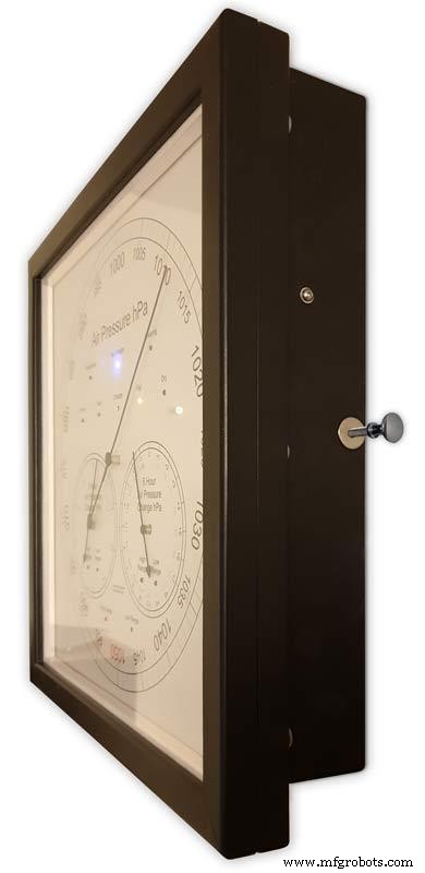
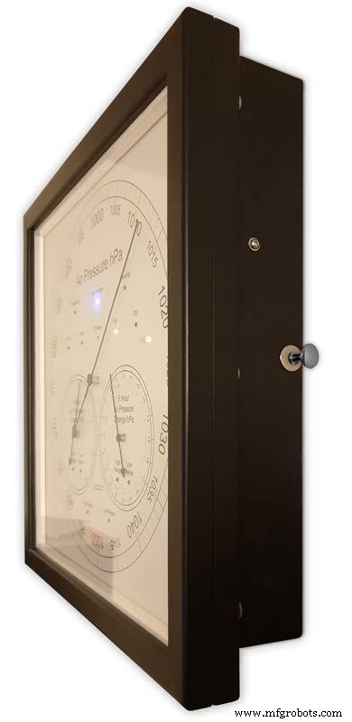
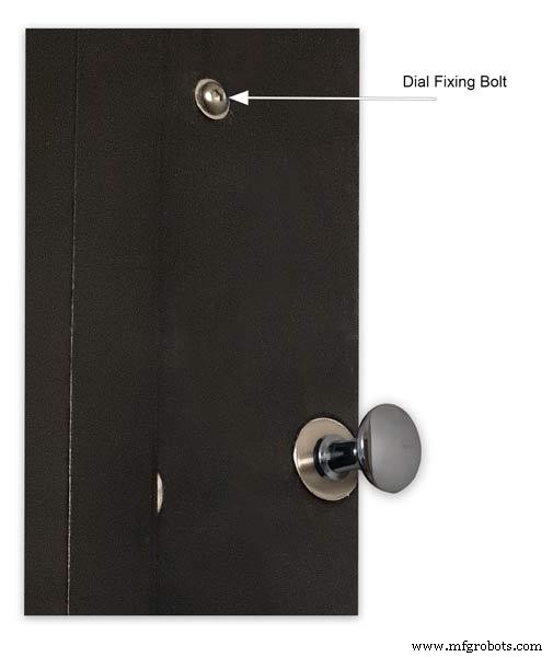
Pic.8 Steel Locking Pin This is a small cabinet knob with a length of treaded bar screwed into the thread.
Pic.9 &10 The locking pin when pushed fully in lock the barometer against the wall. When pulled out the barometer is able to swing out to allow access to the control switched and LCD displays.
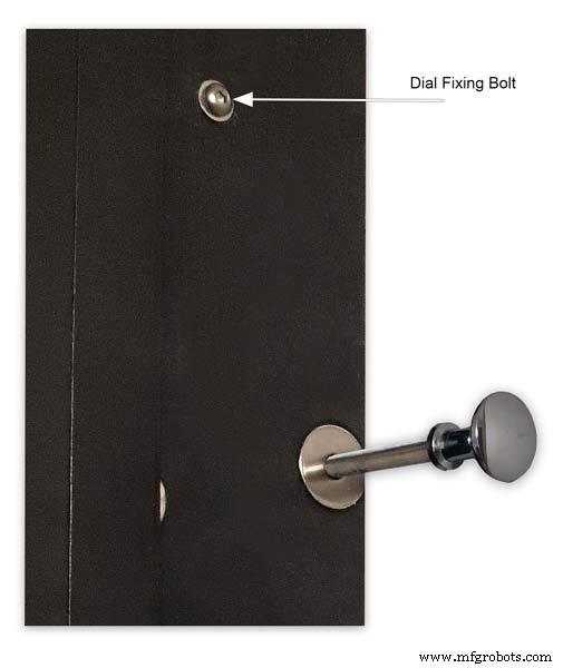
Pic.11 Detail of Locking Pin and location of right side dial fixing bolt. I have glued a washer in place over the hole as an escutcheon plate.
Step 21:Construction Modern Case Dial Mounting

The dial and all the boards etc are removable for maintenance and is held to the backbox by 2 bolts.
Mounting the Dial in the Back Box
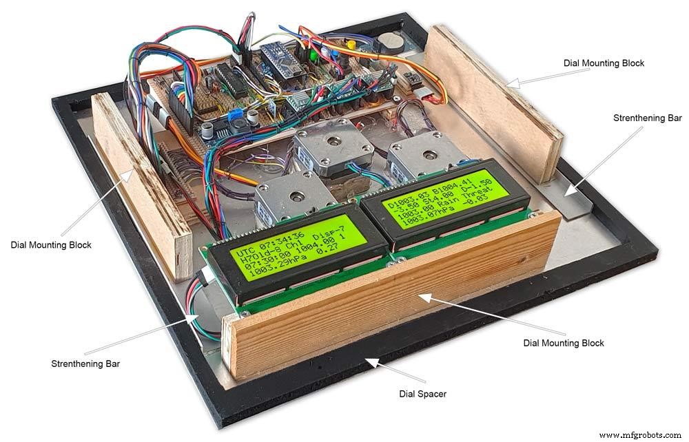
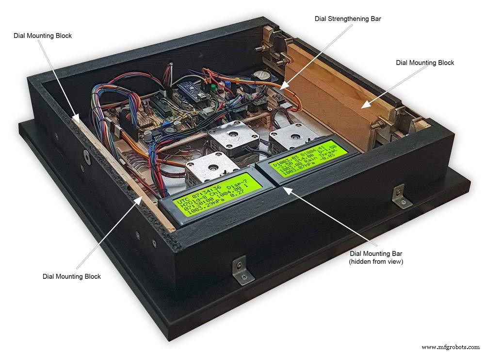
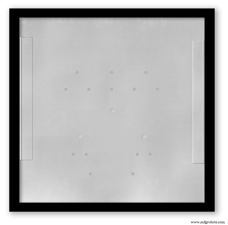
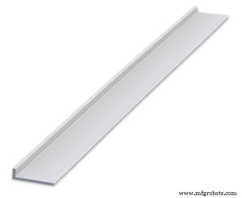
The dial holds the combined weight of all the stepper motors, boards and modules and is stiffened by impact gluing two strips of unequal aluminium angle to it's rear surface.Two blocks of wood are then glued to these bars and small screws then hold these wooden blocks through the side of the back box. A further thin strip of wood is glued to the dial below the LCD mounting block. This is not screwed to the case but sits on the back box to support the dial.
Pic.1 Strengthening bar of alluminium unequal angle.
Pic.2 Strengthening bar locations.
Pic.3 Glued wooden fixing/support blocks for dial fixing bolts left and right and glued dial support lower.
Pic.4 Shows contact/fixing points between the back box and dial. Back box in black with dial fixings/support in wood.
Pic.5 Rear view showing mounting block and bar locations.
Pic.6 Dial with Back Box Removed showing mounting blocks and strengthening bars glued to the rear of the dial.
The dial spacer allows the dial to sit flush with the top of the rear picture frame.
Pic.7 Right side of clock showing dial fixing bolt location.
Pic.8 A mount is constructed from 4 thin strips of wood and is placed in the recess of the front picture frame. This fills the gap between the picture frame and dial, holds the Perspex sheet in place and also adds a photo mount effect to the dial.
Pic.9 Mount in place behind the front picture frame.
Step 22:Contruction Dial
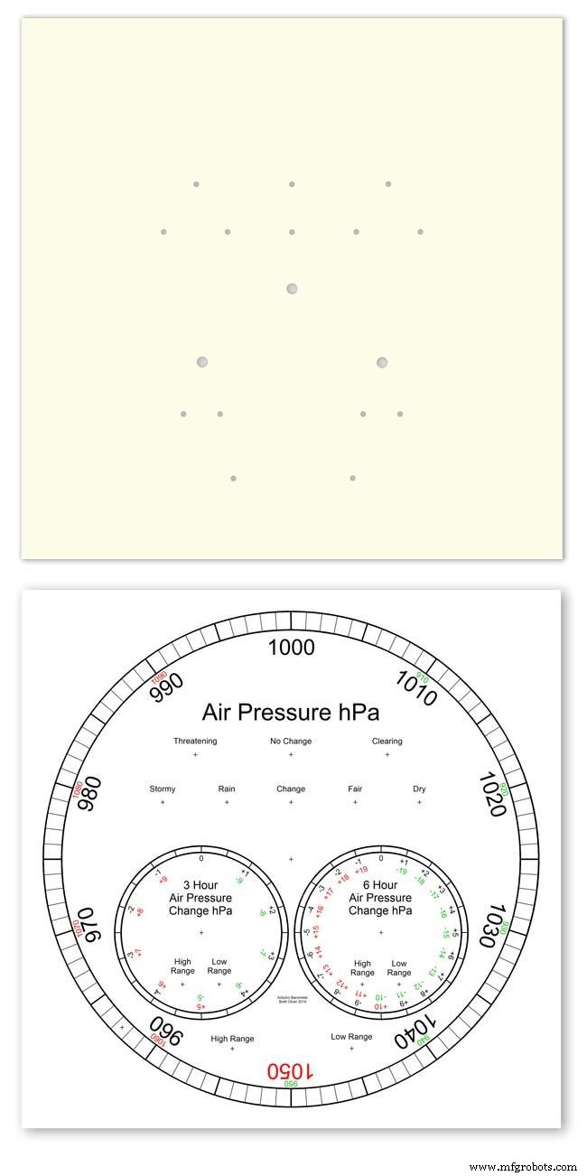
Pic.1 The dial is made from 1.5mm thick alluminium sheet and comes covered with a protective plastic film.
Pic.2 From your cad program print out the dial on A3 paper and include center marks for all the LED and stepper motor shaft holes.This will be your drill template.Lay the paper of the alluminium dial blank and tape the edges to stop it moving.Center punch all the holes through the paper.
Pic.3 Remove the paper template and drill out the holes 3mm for the LEDs and 3 larger holes for your stepper motor spindle.
Start with a small pilot hole and increase the drill size in 3 stages. If you are using a round dial mark it out on the projective film with a market pen and cut it out at this stage.
Pic.4 The protective plastic film can now be removed. Rub down the dial back and front to remove any burrs and to provide a key for the paint.
Pic.5 Spray a coat of acrylic primer and then your choice of top coat - I have used antique white.
I then give a final coat of matt clear acrylic. Leave to dry over night.
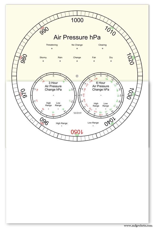
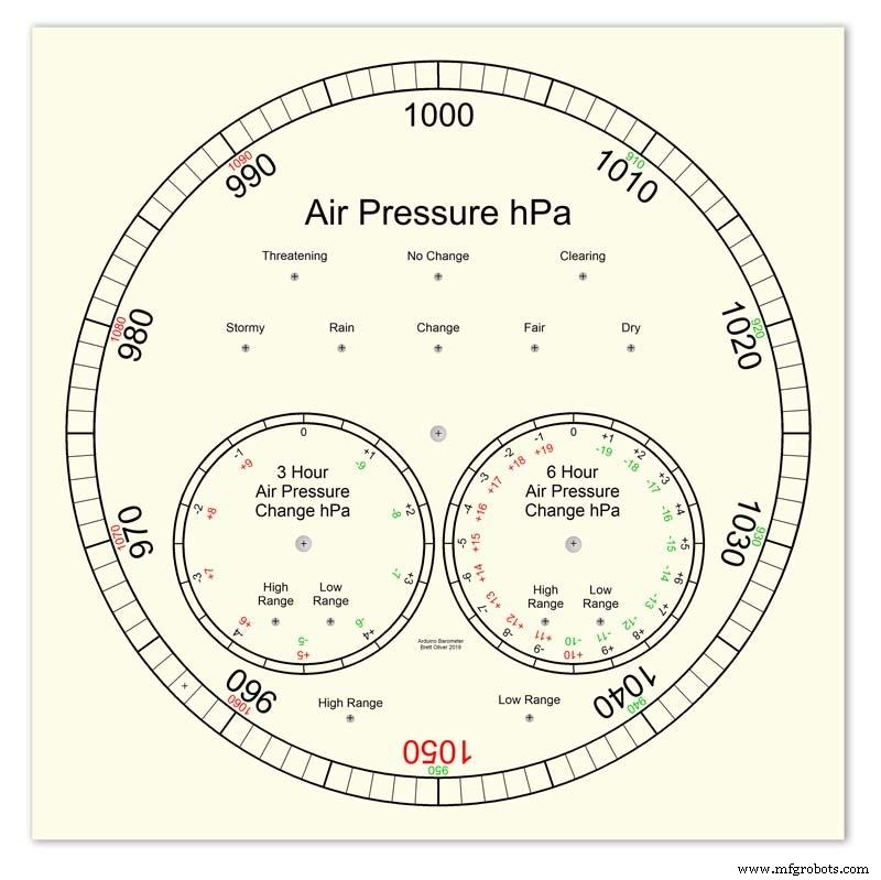
I have included a high res pic of the dial pic.6. Contact me if you need it in another format. My CAD format is TurboCad.
Step 23:Construction Dial Decal
Apply the water slide decal transfer.
I use Water Slide Decal paper from BIGBITE Studio They have some good tutorials on their site. https://www.bigbitestudio.co.uk/tutorials/water-decal-tutorials/
Pic.1 Water slide decals are printed out on an inkjet printer soaked in water then slid into place. They give a very detailed print and once given a coat of varnish are tough.
Don't forget to order transparent transfers so the dial colour can be seen through the transfer.Follow the instructions with the pack as they do vary.
Pic.2 On my transfers I print out the dial on transfer paper let it dry and then cut it out to just under the size of the dial. I then give it a coat of acrylic varnish.
I set my printer as follows:Plain Paper, Photo &High Speed Off This stops my printer from over inking the paper When the varnish is dry the transfer is soaked in water until the transparent transfer comes away from the white backing sheet.
Pic.3 Move the soaked transfer over the dial.
Pic.4 Slide the transfer into position.
Pic.5 Gently pull the white backing paper backward while holding the transfer down.
Make sure the crosses line up with the center of all the holes.
Pic.6 Get rid of any air bubbles.
Pic.7 Then leave it to dry before adding a coat of matt varnish.
After the coat of varnish break through the layer of transfer over the holes using the back of a drill bit jus smaller than the holes. Then give a final coat of varnish to seal the edges around the holes.
Step 24:Construction Hands
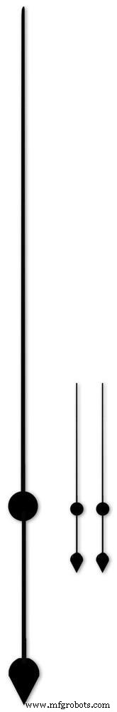
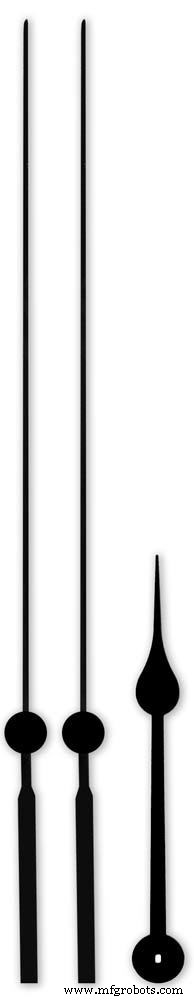

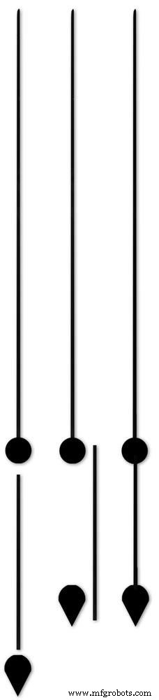


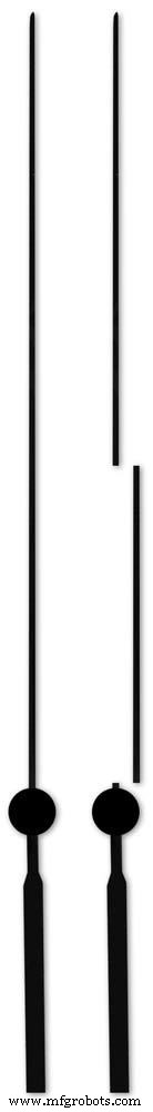
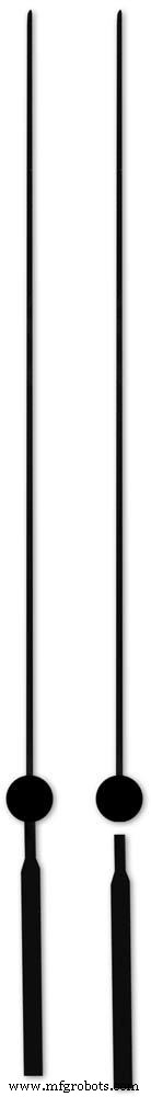
Hands are a very personnal choice and there are many diffent styles to choose from. The hardest part is finding hands that match each other. I found a perfect set of small hands but was unable to find a matching longhand for the main barometer. In the end I made my own from 3 donor hands.
All my hands were quartz second hands so I hand to file the mounting spindle off the back for mounting on the stepper motor spindle.
On some stepper motors the spindle can be drilled out to take the hand spindle but my spindles were too hard to drill.
Pic.1 my completed hands.
Pic.2 The long barometer hand was constructed from 3 different hands
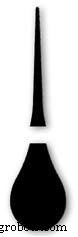
Pic.3 To get the lower spade balance part of the hand I used a spade hand.
Pic.4 First I cut off the top using sharp scissors.
Pic.5 The top was then trimmed by cutting the point off.
Pic.6 The remaining part was then filed away to match the shape of the 2 smaller hands.
Pic.7 The completed balance for the hand.
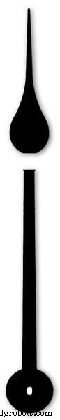
Pic.8 To make the front pointer and center I cut the end off one off my donor hands.
Pic.9 To make the rear balance shaft I cut a section out of the 3rd donor hand.
Pic.10 Left the 3 parts of the new hand. Middle shows the overlap of the balance shaft to allow for bonding. Right pic shows the balance shaft bonded with impact adhesive to the underside of the balance and center shaft.
To fix the hands to the stepper motor spindle I did not want to use impact adhesive as the hands are fragile and would be damaged if I hand to remove them. In the end I went for a tiny bit of Blu Tack on each hand. Blu Tack is putty like and is non setting but seems to hold very well!
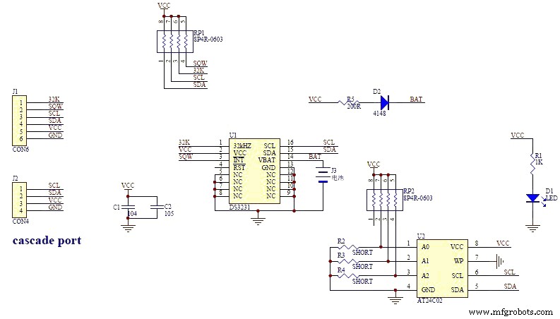
Step 25:Construction Schematic
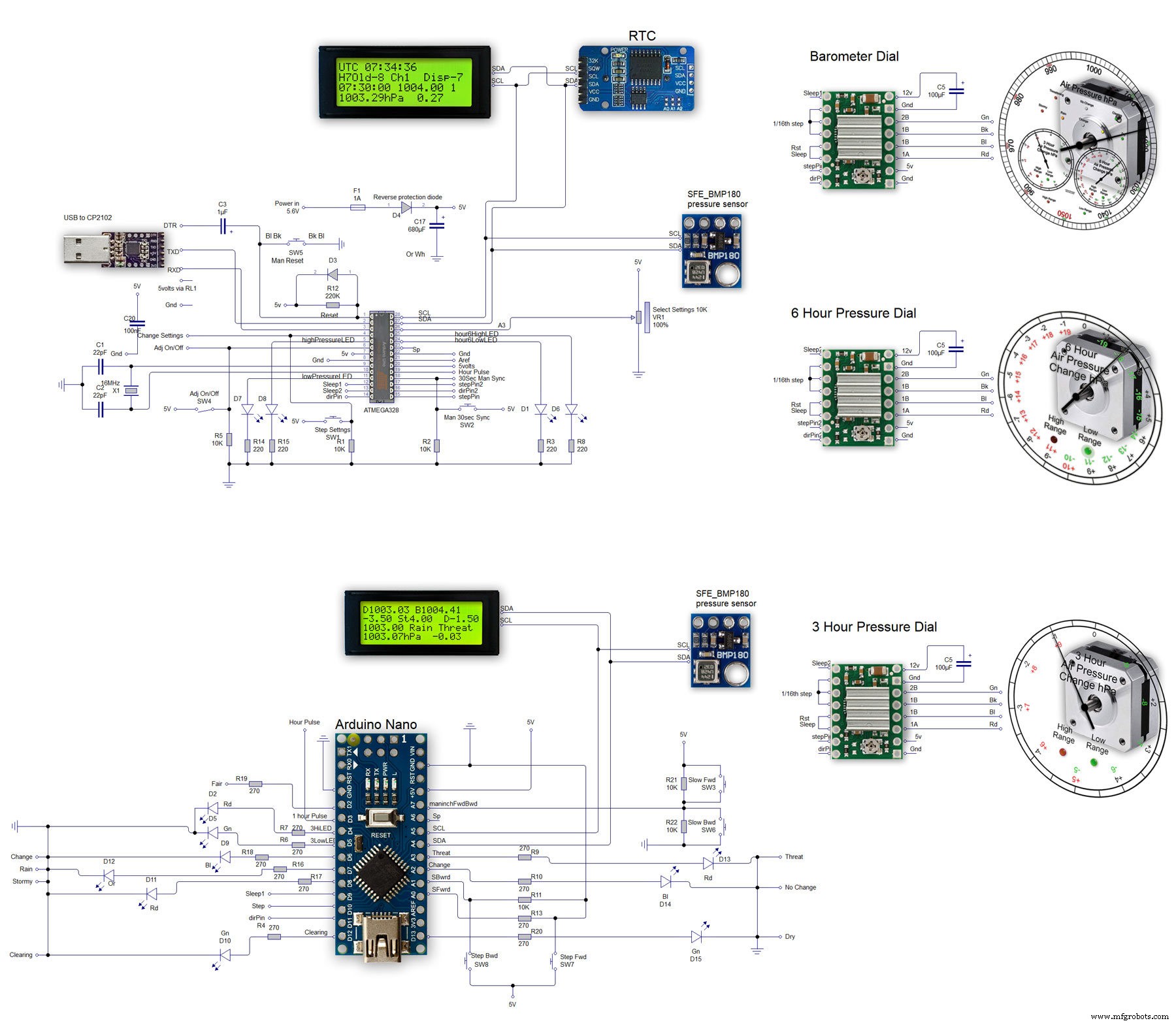
The main shematic is shown in Pic. 1 with the power supply in Pic.2.
You will also need a regulated plug in 12v supply adaptor of around 1amp.
Note I have fitted switches on the LCD displays to turn the backlight LEDs On and Off. This is optional but as the displays are not visible for 99.99% of the time it will save power.
Note larger schematics can be found on my web site here
Step 26:Construction Vero Board
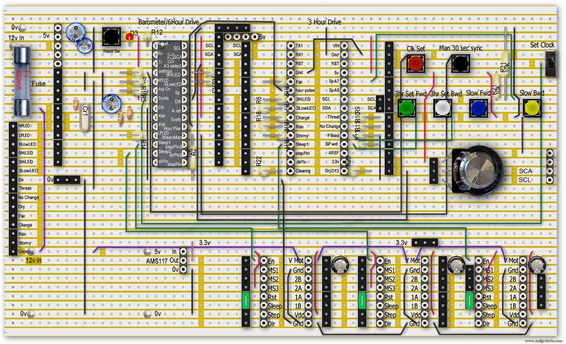
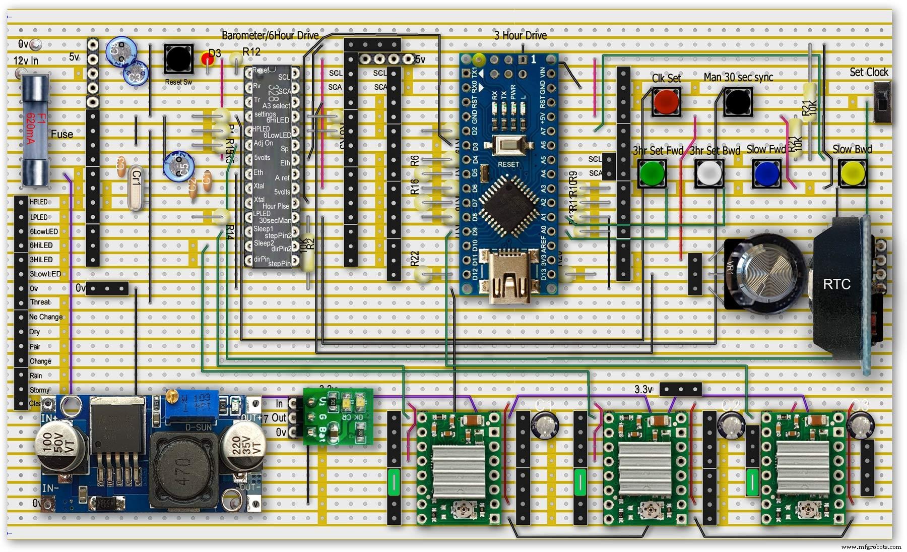
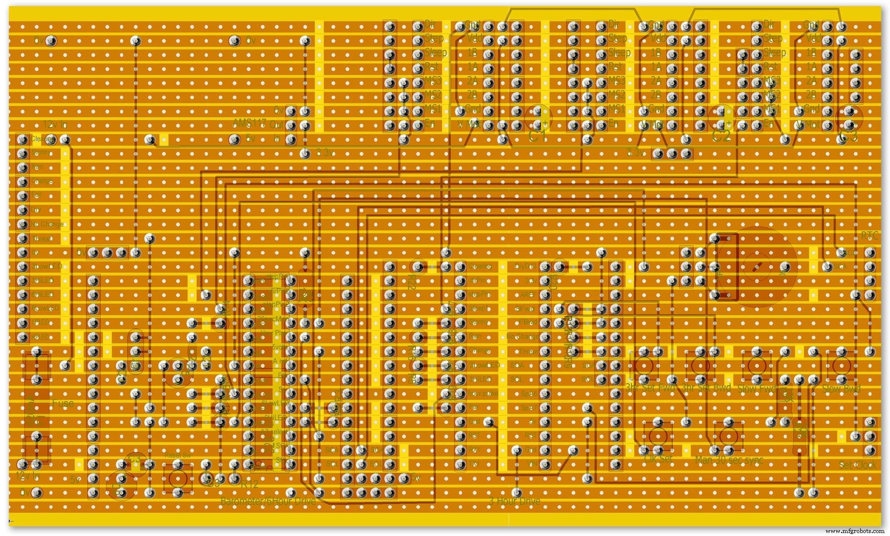
Vero Board Layouts
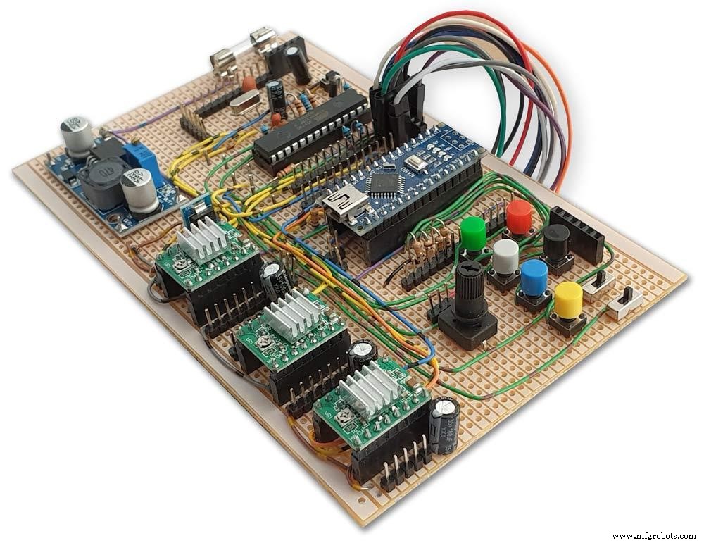
Pic.1 Vero Board with all modules removed.
Pic.2 Vero Board with modules in place.
Pic.3 Vero Board rear view (flipped down from top).
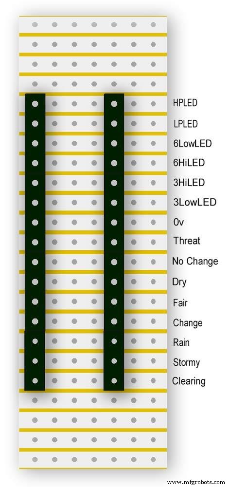
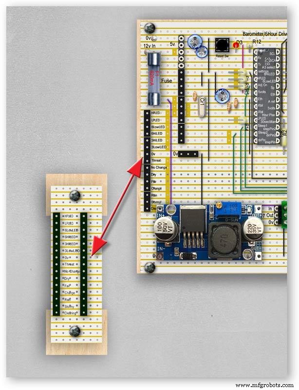
Pic.4 LED Vero Board
This board is used as a connection point for the dial LEDs. This allows the dial to be disconnected from the main board if required for maintenance.
Pic.5 The LED Vero Board connects to the main board with Dupont sockets and male Dupont cable
Pic.6 Vero Board wiring in progress.
Pic.7 Vero Boards and module location on the rear of the dial.
Step 27:Code
Code
There are 2 parts to the code 1 for the Main Barometer Code and 6 hour display and 1 for the 3 hour display and weather forecast.
Step 28:Time-Lapse Video
Time-Lapse Video showing rain radar and the Barometer predicting rain and a storm.
This is a 4K video so you should be able to see full details of the dial and forecast LEDs.
Code
- BarometerA4988_23.ino
- BarometerA4988_3hour__21.ino
BarometerA4988_23.inoArduino
Main file for Barometer and 6 hour display/* Example sketch to control a 28BYJ-48 stepper motor with ULN2003 driver board, AccelStepper and Arduino UNO:number of steps/revolutions. More info:https://www.makerguides.com v4 moved step 6 hour pressure step from void getpressure 1523 to main loop check every hour 365v5 remove unwamted step elementsv6 convert to diff display on 6 hr motorv8 modified hour change formula 1486v9 sleepv10 chnged high/low for EN control v11 chenge calc for hour change 1380v12 added calcCurrentDisp (); to calc current time from line 1384v13 removed 30 sec syncv14 air pressure extremes LEDsv15 add hour diff hour calc etc to row 1 when not on settingsv16 adding 16th stepsv17 errorv18 change min pulse to hour pulse on the hour + 1minv19 check enable and sleepsv20 added DAC to NANO so pins changed on 328 to match (analogue and digital swapped A6 D3 - deleted v20 also changed Low range hi range to both light above 19 or -19v21 same as 20 with serial print removedv23 notes added LCD display info added to startup */#include//SFE_BMP180 pressure sensor#include #include #include // ######## You will need to create an SFE_BMP180 object, here called "pressure":SFE_BMP180 pressure;#define ALTITUDE 118.0 // Altitude of Kenley Surrey in meters// also used to adjust/sync/calibrate to nearby weather station/3 hour display//#########//**********************// set the LCD address to 0x27 for a 20 chars 4 line display// Set the pins on the I2C chip us ed for LCD connections:// addr, en,rw,rs,d4,d5,d6,d7,bl,blpolLiquidCrystal_I2C lcd(0x27, 2, 1, 0, 4, 5, 6, 7, 3, POSITIVE); // Set the LCD I2C address#define DS3231_I2C_ADDRESS 0x68// Convert normal decimal numbers to binary coded decimalbyte decToBcd(byte val){ return( (val/10*16) + (val%10) );}// Convert binary coded decimal to normal decimal numbersbyte bcdToDec(byte val){ return( (val/16*10) + (val%16) );}// Include the AccelStepper library:#include // Define stepper motor connections and motor interface type. Motor interface type must be set to 1 when using a driver:#define dirPin 8#define stepPin 9#define dirPin2 10#define stepPin2 11#define motorInterfaceType 1// Create a new instance of the AccelStepper class:AccelStepper stepper =AccelStepper(motorInterfaceType, stepPin, dirPin);//barometer motorAccelStepper stepper2 =AccelStepper(motorInterfaceType, stepPin2, dirPin2);// 6 hour motorfloat seaPressure =0;float pressureNow =0;float pressurePrevious =0;float pressureDiff =0;int checkStop =0;int pressureRndDiff =0;int pressureRndNow =0;int pressureRndPrevious =0;int adjustOn =4; // allows adjustment of barometer// int test =0; // test mode 0 off 1 is onchar status; double T,P,a;//int h =0;//int m =0;//int j =0;int stepcount =0;int time =0;int resetmins =1;int secondNow =0;int secondPrevious=0;int minuteNow =0;int minutePrevious=0;int hourNow =0;int hourPrevious=0;int hourNow1=0;int hourPrevious1=0;int initial =0;int initial1 =0;int initial3 =0;int highPressureLED =3;int lowPressureLED =5;int hour6LowLED =15;int hour6HighLED =16;int manSync =12; // resets seconds to 30 secondsint changeSetting =2;int syncStop =0;int sync30Stop =0;int stepoffHour =0;int stepoffHourbkw =0;int stepoffMin =0;int stepoffMinbwd =0;int stepoffRTCminfwd =0;int stepoffRTCminbwd =0;int stepoffRTChourfwd =0;int stepoffRTChourbwd =0;int settingreadPin =A3; //Pin for sensing analogue value from potint settingVal =0; // Analogue value 0-1023int LCDstop =0; // stops settings on LCD display refreshing until they changeint hourPulse =13; //min pulse for seconds display was 14int adjustLock =0; // turns off adjust lockint hourcalc =0; // number from 0 to 7 representing the 8 hours of stored pressure readings int hourDiff =0; // used to check if 6hour previous motor should be stepped.int hourChange =0; // the amount of 6 hour to stepint currentDisplay =0; //current 6hour change readingint hour0 =1013; // you can set last 8 hours pressure here or leave at 0 and theint hour1 =1014; // readings will catch up over the next 8 hoursint hour2 =1015;int hour3 =1016;int hour4 =1016;int hour5 =1016;int hour6 =1012;int hour7 =1013;int sleep1 =6;int sleep2 =7;// check air pressure here https://www.meteoplug.com/cgi-bin/meteochart.cgi?draw=a3aeaaa1acbdf9f1fcfed4fedbc2c094c0d6d6d1d2c5edcebbfee9ffeff1fbf9//int Disp3hrIn =A3;//int Disp3hrVal =0;void setup() { pinMode(adjustOn, INPUT); pinMode(hourPulse, OUTPUT); pinMode(highPressureLED, OUTPUT); pinMode(lowPressureLED, OUTPUT); pinMode(hour6LowLED, OUTPUT); pinMode(hour6HighLED, OUTPUT); pinMode(manSync, INPUT); pinMode(sleep1, OUTPUT); pinMode(sleep2, OUTPUT); pinMode(settingreadPin, INPUT); // Set the maximum steps per second:stepper.setMaxSpeed(1000); stepper2.setMaxSpeed(1000); lcd.begin(20,4); // initialize the lcd for 20 chars 4 lines, turn on backlight lcd.backlight(); // backlight on not needed as man controlled lcd.setCursor(0,0); //Start at character 0 on line 0 lcd.print("Barometer A988"); //@@@@@@@@@@@@@@@@@@@@@@@@@@@@@@@@@@@@@@@@@@@@@@@@@@@@@@@@@@@@@@@@@@@@@@@@@@@@@@@@@@@@@@@@@@@@@@@@@@@@@@@@@@@@@@@@@@@@@@@@@@@@@@@@ lcd.setCursor(0,1); //Start at character 0 on line 1 lcd.print(" Version 23"); //@@@@@@@@@@@@@@@@@@@@@@@@@@@@@@@@@@@@@@@@@@@@@@@@@@@@@@@@@@@@@@@@@@@@@@@@@@@@@@@@@@@@@@@@@@@@@@@@@@@@@@@@@@@@@@@@@@@@@@@@@@@@@@@@ { Wire.begin(); Serial.begin (9600); // set the initial time here:// DS3231 seconds, minutes, hours, day, date, month, year // setDS3231time(10,42,9,5,18,12,19);//delay(2000);lcd.clear();}Serial.println("REBOOT");// serial removed // Initialize the sensor (it is important to get calibration values stored on the device). if (pressure.begin()) Serial.println("BMP180 init success");// serial removed else { // Oops, something went wrong, this is usually a connection problem, // see the comments at the top of this sketch for the proper connections. Serial.println("BMP180 init fail\n\n");// serial removed while(1); // Pause forever. } //LED TestdigitalWrite(hour6HighLED, HIGH);delay (500);digitalWrite(hour6HighLED, LOW);digitalWrite(hour6LowLED, HIGH);delay (500);digitalWrite(hour6LowLED, LOW);digitalWrite(highPressureLED, HIGH);delay (500);digitalWrite(highPressureLED, LOW);digitalWrite(lowPressureLED, HIGH);delay (500);digitalWrite(lowPressureLED, LOW);delay (500);lcd.clear();getPressure ();// gets all pressure readings// Disp readings on startup so hands can be set lcd.setCursor(0,1); lcd.print(" "); lcd.setCursor(0,1); lcd.print("H"); lcd.print(hourcalc); lcd.setCursor(2,1); lcd.print(" "); lcd.setCursor(2,1); lcd.print("Old"); lcd.print(currentDisplay); lcd.setCursor(13,1); lcd.print(" "); lcd.setCursor(13,1); lcd.print("Disp"); lcd.print(hourDiff); //disable motors on startupdigitalWrite(sleep1, HIGH);digitalWrite(sleep2, HIGH);stepper.disableOutputs();stepper2.disableOutputs();// test =1; // test set to 0 off 1 on}void loop() { if( digitalRead(adjustOn) ==HIGH || adjustLock ==1)// only alow settings when change settings switch is ON{ //digitalWrite(sleep1, LOW);//enable on //digitalWrite(sleep2, LOW);//enable on only enable outputs for 2 mins Settings(); //set what function the setiing switches have adjustLock =1; //hold on adjustment if( digitalRead(adjustOn) ==LOW){//digitalWrite(sleep1, HIGH);//disable on//digitalWrite(sleep2, HIGH);//enable on only enable outputs for 2 minsadjustLock =0; //hold on adjustment } }// only allow settings change when setting switch is on // displayTime(); // display the real-time clock data on the Serial Monitor, byte second, minute, hour, dayOfWeek, dayOfMonth, month, year; // retrieve data from DS3231 readDS3231time(&second, &minute, &hour, &dayOfWeek, &dayOfMonth, &month, &year);//@@@@@@@@@@@@@@@@@@@@@@@@@@@@@@@@@@@@@@@@@@@@@@@@@@@@@@@@@@@@@@@@@@@@@@@@@@@@@@@@@@@@@@@@@@@@@@@@@@@@@@@@@@@@@@@@@ //enable air pressure readings if (minute ==9 || minute ==19 || minute ==29 || minute ==39 || minute ==49 || minute ==59 &&second ==59) { checkStop =0;// resets checkstop to allow air pressure readings every 10 mins }//check air pressure every 10 mins if (checkStop ==0) { if ( minute ==0 || minute ==10 || minute ==20 || minute ==30 || minute ==40 || minute ==50 ) { //digitalWrite(sleep1, LOW);//enable on -only enable outputs for 1 min // only sleep1 needs activation getPressure ();// gets all pressure readings checkStop =1;// stops multiple readings of air pressure }// else //digitalWrite(sleep1, HIGH);//enable off // Serial.print("Sleep 1 HIGH (off) "); // Serial.println(hourChange); } //@@@@@@@@@@@@@@@@@@@@@@@@@@@@@@@@@@@@@@@@@@@@@@@@@@@@@@@@@@@@@@@@@@@@@@@@@@@@@@@@@@@@@@@@@@@@@@@@@@@@@@@@@@@@@@@@if(digitalRead(manSync)==HIGH)// resets seconds to 30{ setDS3231time(30, minute, hour, dayOfWeek, dayOfMonth, month, year); //Set seconds to 30 on RTC } // counts seconds secondNow =second; if(secondNow!=secondPrevious || initial) { lcd.setCursor(0,0); lcd.print("UTC "); if(hour<10) { lcd.print(0); } lcd.print(hour); lcd.print(":"); if(minute<10) { lcd.print(0); } lcd.print(minute); lcd.print(":"); if(second<10) { lcd.print(0); } lcd.print(second); lcd.print(" "); // Serial.print("-1*0 ");// Serial.println(-1*0); initial =0; secondPrevious =secondNow; } // count minutes minuteNow =minute; if(minuteNow!=minutePrevious || initial) //settingVal <690 stops clock motors operating when setting RTC { initial =0; minutePrevious =minuteNow; // digitalWrite(minPulse,HIGH);//1 min pulse for seconds display sync syncStop =0;// clock will not sync again untill a new minute has started. // digitalWrite(minPulse,LOW);//1 min pulse for seconds display sync } // counts hours + 1min for hourPulse at 15 seconds past the hour this allows barometer and 6 hour dial to step first if ( minute ==0 &&second ==15) // send hour pulse 15 seconds past the hour to 3 hour circuit allows other motors to stop { digitalWrite(hourPulse,HIGH); digitalWrite(highPressureLED,HIGH); // Serial.println("hourPulse Hi "); } else if (minute !=1 || second !=0) { digitalWrite(hourPulse,LOW);digitalWrite(highPressureLED,LOW); }// counts hours hourNow =hour; if ((minute ==59 &&second> 50) || (minute ==0 &&second <10) )// allows change on the hour only {// digitalWrite(sleep2, LOW);// enable 6hr motor if(hourNow!=hourPrevious || initial) //settingVal <690 stops clock motors operating when setting RTC { initial =0; hourPrevious =hourNow;//print hour stores every hour // serial removed /* Serial.print("hour0 "); Serial.println(hour0); Serial.print("hour1 "); Serial.println(hour1); Serial.print("hour2 "); Serial.println(hour2); Serial.print("hour3 "); Serial.println(hour3); Serial.print("hour4 "); Serial.println(hour4); Serial.print("hour5 "); Serial.println(hour5); Serial.print("hour6 "); Serial.println(hour6); Serial.print("hour7 "); Serial.println(hour7); */ //##############################################################################//step 6 hour motorif (hourChange> 0 &&hourChange <40) // 6 hour motor will not step if diff> 10 { stephourFwd(); //Serial.print("Step 6 hour Forward ");// serial removed // Serial.println(hourChange);// serial removed hourChange =0; } else if (hourChange <0 &&hourChange> -40) // else if (hourDiff ==-1 || test ==1) { stephourBwd(); // Serial.print("Step 6 Hour Backward ");// serial removed // Serial.println(hourChange);// serial removed hourChange =0; } // hourChange =0; //############################################################################## } // digitalWrite(sleep2, HIGH);// disable 6hr motor// add LCD stop if(second==0) { // lcd.setCursor(0,1); //lcd.print(" "); lcd.setCursor(0,1); lcd.print(" "); lcd.setCursor(0,1); lcd.print("H"); lcd.print(hourcalc); lcd.setCursor(2,1); lcd.print(" "); lcd.setCursor(2,1); lcd.print("Old"); lcd.print(currentDisplay); lcd.setCursor(13,1); lcd.print(" "); lcd.setCursor(13,1); lcd.print("Disp"); lcd.print(hourDiff); } } } // Set Clock/Motors###################################################################################################//gets advance retard settings from potvoid Settings(){ settingVal =analogRead(settingreadPin); // read the value from the pot if ( settingVal>=0 &&settingVal <85 ) { setMinsfwd(); } if ( settingVal>=85 &&settingVal <170 ) { setMinsbwd(); } if ( settingVal>=170 &&settingVal <255 ) { setMinsslowfwd(); } if ( settingVal>=255 &&settingVal <340 ) { setMinsslowbkd(); } if ( settingVal>=340 &&settingVal <425 ) { setHoursfwd(); } if ( settingVal>=425 &&settingVal <510 ) { setHoursbwd(); } if ( settingVal>=510 &&settingVal <595 ) { setHoursslowfwd(); } if ( settingVal>=595 &&settingVal <690 ) { setHourslowbkd(); } if ( settingVal>=690 &&settingVal <765 ) { setRTCfwdmin(); } if ( settingVal>=765 &&settingVal <850 ) { setRTCbwdmin(); } if ( settingVal>=850 &&settingVal <900 ) { setRTCfwd(); } if ( settingVal>=900 &&settingVal <970 ) { setRTCbwd(); }if ( settingVal>=970 &&settingVal <1025 ) { } if ( settingVal>=0 &&settingVal <85 &&LCDstop==0)// LCDstop prevents the LCD from freshing until another item is selected { lcd.setCursor(0,1); lcd.print(" "); lcd.setCursor(0,1); lcd.print("Barometer Advance"); LCDstop=1; } if ( settingVal>=85 &&settingVal <170 &&LCDstop==1) { lcd.setCursor(0,1); lcd.print(" "); lcd.setCursor(0,1); lcd.print("Barometer Retard"); LCDstop=0; } if ( settingVal>=170 &&settingVal <255 &&LCDstop==0 ) { lcd.setCursor(0,1); lcd.print(" "); lcd.setCursor(0,1); lcd.print("Baro Inch Advance"); LCDstop=1; } if ( settingVal>=255 &&settingVal <340 &&LCDstop==1 ) { lcd.setCursor(0,1); lcd.print(" "); lcd.setCursor(0,1); lcd.print("Baro Inch Retard"); LCDstop=0; } if ( settingVal>=340 &&settingVal <425 &&LCDstop==0 ) { lcd.setCursor(0,1); lcd.print(" "); lcd.setCursor(0,1); lcd.print("6Hr Baro Advance"); LCDstop=1; } if ( settingVal>=425 &&settingVal <510 &&LCDstop==1 ) { lcd.setCursor(0,1); lcd.print(" "); lcd.setCursor(0,1); lcd.print("6Hr Baro Retard"); LCDstop=0; } if ( settingVal>=510 &&settingVal <595 &&LCDstop==0 ) { lcd.setCursor(0,1); lcd.print(" "); lcd.setCursor(0,1); lcd.print("6Hr Baro Inch Advn"); LCDstop=1; } if ( settingVal>=595 &&settingVal <690 &&LCDstop==1 ) { lcd.setCursor(0,1); lcd.print(" "); lcd.setCursor(0,1); lcd.print("6Hr Baro Inch Retard"); LCDstop=0; } if ( settingVal>=690 &&settingVal <765 &&LCDstop==0) { lcd.setCursor(0,1); lcd.print(" "); lcd.setCursor(0,1); lcd.print("RTC Min Advance"); LCDstop=1; } if ( settingVal>=765 &&settingVal <850 &&LCDstop==1 ) { lcd.setCursor(0,1); lcd.print(" "); lcd.setCursor(0,1); lcd.print("RTC Min Retard"); LCDstop=0; } if ( settingVal>=850 &&settingVal <900 &&LCDstop==0 ) { lcd.setCursor(0,1); lcd.print(" "); lcd.setCursor(0,1); lcd.print("RTC Hour Advance"); LCDstop=1; } if ( settingVal>=900 &&settingVal <970 &&LCDstop==1 ) { lcd.setCursor(0,1); lcd.print(" "); lcd.setCursor(0,1); lcd.print("RTC Hour Retard"); LCDstop=0; } if ( settingVal>=970 &&settingVal <1025 &&LCDstop==0 ) { lcd.setCursor(0,1); lcd.print(" "); lcd.setCursor(0,1); lcd.print("OFF"); LCDstop=1; } }// END of Loop// set RTC min forward 1 min per press ##################################################################################void setRTCfwdmin(){ if( digitalRead(changeSetting) ==HIGH &&stepoffRTCminfwd ==0 ) { byte second, minute, hour, dayOfWeek, dayOfMonth, month, year; // retrieve data from DS3231 readDS3231time(&second, &minute, &hour, &dayOfWeek, &dayOfMonth, &month, &year); minute =minute+1; if (minute ==60) { minute =0; } setDS3231time(second, minute, hour, dayOfWeek, dayOfMonth, month, year); //Set seconds to 30 on RTC stepoffRTCminfwd =1; } if( digitalRead(changeSetting) ==LOW ) { stepoffRTCminfwd =0; }}//##################################################################################// set RTC min backward 1 min per press ##################################################################################void setRTCbwdmin(){ if( digitalRead(changeSetting) ==HIGH &&stepoffRTCminbwd ==0 ) { byte second, minute, hour, dayOfWeek, dayOfMonth, month, year; // retrieve data from DS3231 readDS3231time(&second, &minute, &hour, &dayOfWeek, &dayOfMonth, &month, &year); minute =minute-1; if (minute <1) { minute =59; } setDS3231time(second, minute, hour, dayOfWeek, dayOfMonth, month, year); //Set seconds to 30 on RTC stepoffRTCminbwd =1; } if( digitalRead(changeSetting) ==LOW ) { stepoffRTCminbwd =0; }}//##################################################################################//###################################################################################################// set RTC hour forward 1 hour per press ##################################################################################void setRTCfwd(){ if( digitalRead(changeSetting) ==HIGH &&stepoffRTChourfwd ==0 ) { byte second, minute, hour, dayOfWeek, dayOfMonth, month, year; // retrieve data from DS3231 readDS3231time(&second, &minute, &hour, &dayOfWeek, &dayOfMonth, &month, &year); hour =hour+1; setDS3231time(second, minute, hour, dayOfWeek, dayOfMonth, month, year); //Set seconds to 30 on RTC stepoffRTChourfwd =1; } if( digitalRead(changeSetting) ==LOW ) { stepoffRTChourfwd =0; }}//##################################################################################// set RTC hour backward 1 hour per press ##################################################################################void setRTCbwd(){ if( digitalRead(changeSetting) ==HIGH &&stepoffRTChourbwd ==0 ) { byte second, minute, hour, dayOfWeek, dayOfMonth, month, year; // retrieve data from DS3231 readDS3231time(&second, &minute, &hour, &dayOfWeek, &dayOfMonth, &month, &year); hour =hour-1; setDS3231time(second, minute, hour, dayOfWeek, dayOfMonth, month, year); //Set seconds to 30 on RTC stepoffRTChourbwd =1; } if( digitalRead(changeSetting) ==LOW ) { stepoffRTChourbwd =0; }}//##################################################################################// set Minutes Motor forward 1 min per press ##################################################################################void setMinsfwd(){ //digitalWrite(sleep1, LOW); //stepper.enableOutputs();// step minutes 1 min per press if( digitalRead(changeSetting) ==HIGH &&stepoffMin ==0 ) { //Serial.println("Step Forward Man");// serial removed stepoffMin =1; stepminsFwd(); } if( digitalRead(changeSetting) ==LOW ) { stepoffMin =0; }//digitalWrite(sleep1, HIGH); //stepper.disableOutputs();}//##################################################################################// set Minutes Motor backward 1 min per press ##################################################################################void setMinsbwd(){ //digitalWrite(sleep1, LOW); // stepper.enableOutputs(); if( digitalRead(changeSetting) ==HIGH &&stepoffMinbwd ==0 ) { // Serial.println("Step Backward Man");// serial removed stepoffMinbwd =1; stepminsBwd(); } if( digitalRead(changeSetting) ==LOW ) { stepoffMinbwd =0; }//digitalWrite(sleep1, HIGH); // stepper.disableOutputs();}//##################################################################################// step minutes slow forward const press ##################################################################################void setMinsslowfwd(){ stepper.enableOutputs(); digitalWrite(sleep1, LOW); if( digitalRead(changeSetting) ==HIGH ) { // Serial.println("Step Baro Inch Forward Man");// serial removed stepper.setCurrentPosition(0); // Run the motor forward at 500 steps/second until the motor reaches 4096 steps (1 revolution):while (stepper.currentPosition() !=1) { //was 52 52x60 =3120 stepper.setSpeed(50); stepper.runSpeed(); } /* digitalWrite(motorPin1, LOW); digitalWrite(motorPin2, LOW); digitalWrite(motorPin3, LOW); digitalWrite(motorPin4, LOW);*/ } digitalWrite(sleep1, HIGH); stepper.disableOutputs();}//##################################################################################// step minutes slow backward const press ##################################################################################void setMinsslowbkd(){ stepper.enableOutputs(); digitalWrite(sleep1, LOW); if( digitalRead(changeSetting) ==HIGH ) { // Serial.println("Step Baro Inch Backward Man");// serial removed stepper.setCurrentPosition(0); // Run the motor forward at 500 steps/second until the motor reaches 4096 steps (1 revolution):while (stepper.currentPosition() !=-1) { //was 52 52x60 =3120 stepper.setSpeed(-50); stepper.runSpeed(); } /* digitalWrite(motorPin1, LOW); digitalWrite(motorPin2, LOW); digitalWrite(motorPin3, LOW); digitalWrite(motorPin4, LOW);*/ } digitalWrite(sleep1, HIGH); stepper.disableOutputs();}//##################################################################################// set Hour Motor forward 1 hour per press ##################################################################################void setHoursfwd(){ // stepper2.enableOutputs(); // digitalWrite(sleep2, LOW); // step hours 1 hour per press if( digitalRead(changeSetting) ==HIGH &&stepoffHour ==0 ) { // Serial.println("Step 6hr Forward Man");// serial removed stepoffHour =1; stephourmanFwd(); } // stepper2.disableOutputs(); // digitalWrite(sleep2, HIGH);if( digitalRead(changeSetting) ==LOW ) { stepoffHour =0; }...This file has been truncated, please download it to see its full contents.
BarometerA4988_3hour__21.inoArduino
File for 3 hour display and forecasting/* Example sketch to control a 28BYJ-48 stepper motor with ULN2003 driver board, AccelStepper and Arduino UNO:number of steps/revolutions. More info:https://www.makerguides.com v4 added presure extreme LEDsv5 add forcast LEDs and calcv6 sorted enable and sleep orderv7 remove adjust on and test replace it with Clearing and threatening LEDs PIN 12 and 13 v8 add dac driver-deletedv9 added LCDv10 added weather forecast usingLEDs v12 LEds test addedv13 add 1 dp point to 3 hour displayv14 void 1026 add slow set buttonsv18 voided v19last reading not included in number of stepsv20 change led test orderv20a serial.print removed indicated by // serial removedv21 as 20a identical to v20 that includes serial print*/#include//SFE_BMP180 pressure sensor#include #include // ######## You will need to create an SFE_BMP180 object, here called "pressure":SFE_BMP180 pressure;#define ALTITUDE 125.0 // Altitude of Kenley Surrey in meters//#########//**********************// set the LCD address to 0x27 for a 20 chars 4 line display// Set the pins on the I2C chip used for LCD connections:// addr, en,r w,rs,d4,d5,d6,d7,bl,blpolLiquidCrystal_I2C lcd(0x27, 2, 1, 0, 4, 5, 6, 7, 3, POSITIVE); // Set the LCD I2C address//#define DS3231_I2C_ADDRESS 0x68// Convert normal decimal numbers to binary coded decimalbyte decToBcd(byte val){ return( (val/10*16) + (val%10) );}// Convert binary coded decimal to normal decimal numbersbyte bcdToDec(byte val){ return( (val/16*10) + (val%16) );}// Include the AccelStepper library:#include // Define stepper motor connections and motor interface type. Motor interface type must be set to 1 when using a driver:#define dirPin 11#define stepPin 10#define motorInterfaceType 1// Create a new instance of the AccelStepper class:AccelStepper stepper =AccelStepper(motorInterfaceType, stepPin, dirPin);float seaPressure =0;float pressureNow =0;float pressurePrevious =0;float pressureDiff =0;int checkStop =0;//int pressureRndDiff =0;int pressureRndNow =0;int pressureRndPrevious =0;int adjustOn =12; // allows adjustment of barometer// int test =0; // test mode 0 off 1 is onchar status; double T,P,a;//int h =0;//int m =0;//int j =0;int stepcount =0;//int time =0;//int resetmins =1;//int secondNow =0;//int secondPrevious=0;//int minuteNow =0;//int minutePrevious=0;//int hourNow =0;//int hourPrevious=0;int initial =0;int initial1 =0;int initial3 =0;//int sync30 =3;//30sec sync on pin18//int syncLED =15;//int manSync =12;//int adjustOn =12;//int syncStop =0;//int sync30Stop =0;int stepoffHour =0;int stepoffHourbkw =0;int stepoffMin =0;int stepoffMinbwd =0;//int stepoffRTCminfwd =0;//int stepoffRTCminbwd =0;//int stepoffRTChourfwd =0;//int stepoffRTChourbwd =0;//int settingreadPin =A3; //Pin for sensing analogue value from pot//int settingVal =0; // Analogue value 0-1023int LCDstop =0; // stops settings on LCD display refreshing until they changeint hourPulse =3; //hour pulse from main Barometer Arduinoint adjustLock =0; // turns off adjust lockint hourcalc =0;float hourDiff =0.50; // used to check if 3hour previous motor should be stepped.float hourChange =0.00; // the amount of 3 hour to step float valueint hourStep =0; //the amount of 3 hour to stepint hourStepdigit1 =0; // gets the 1st digit from hourstepint hourStepdigit2 =0; // gets the 2nd digit from hourstepint stepTotal =0; // tptal amount of steps for 3 hour motorint hourChangeNeg =0;// if hour change is -ve this stores the value to chenge stepTotal laterfloat currentDisplay =0.50; //current 3hour change readingfloat hour0 =1036.00; // you can set last 3 hours pressure here or leave at 0 and thefloat hour1 =1036.00; // readings will catch up over the next 4 hoursfloat hour2 =1036.00;float hour3 =1036.00;float hour4 =1036.00;//check readings https://www.meteoplug.com/cgi-bin/meteochart.cgi?draw=a3aeaaa1acbdf9f1fcfed4fedbc2c094c0d6d6d1d2c5edcebbfee9ffeff1fbf9int sleep =9;int hourPulseOff =0;//int testinput =17;int testpulse =0;int hourPlus1min =0;int stepFwd1 =14;int manstepFwd1 =0;int maninchFwdBwd =A7;int stepBwd1 =15;int manstepBwd1 =0;int hour3LowLED =5;// Green low range LEDint hour3HighLED =4;//Red high range LEDint ledStormy =8;int ledRain =7;int ledChange =6;int ledFair =2;int ledDry =13;int ledClear =12;int ledThreat =17;int ledNoChange =16;//Testint n =0;int n1 =0;int n2 =0;void setup() { pinMode(ledStormy, OUTPUT); pinMode(ledRain, OUTPUT); pinMode(ledChange, OUTPUT); pinMode(ledFair, OUTPUT); pinMode(ledDry, OUTPUT); pinMode(ledClear, OUTPUT); pinMode(ledThreat, OUTPUT); pinMode(ledNoChange, OUTPUT); pinMode(stepFwd1, INPUT); pinMode(stepBwd1, INPUT); // pinMode(adjustOn, INPUT); pinMode(hourPulse, INPUT); pinMode(hour3LowLED, OUTPUT); pinMode(hour3HighLED, OUTPUT); pinMode(sleep, OUTPUT); // pinMode(settingreadPin, INPUT); // Set the maximum steps per second:stepper.setMaxSpeed(1000); lcd.begin(20,4); // initialize the lcd for 20 chars 4 lines, turn on backlight lcd.backlight(); // backlight on not needed as controlled by 7 MAX2719 lcd.setCursor(0,0); //Start at character 0 on line 0 lcd.print("Barometer A988 3 Hr"); //@@@@@@@@@@@@@@@@@@@@@@@@@@@@@@@@@@@@@@@@@@@@@@@@@@@@@@@@@@@@@@@@@@@@@@@@@@@@@@@@@@@@@@@@@@@@@@@@@@@@@@@@@@@@@@@@@@@@@@@@@@@@@@@@ lcd.setCursor(0,1); //Start at character 0 on line 0 lcd.print(" Version 20"); //@@@@@@@@@@@@@@@@@@@@@@@@@@@@@@@@@@@@@@@@@@@@@@@@@@@@@@@@@@@@@@@@@@@@@@@@@@@@@@@@@@@@@@@@@@@@@@@@@@@@@@@@@@@@@@@@@@@@@@@@@@@@@@@@ { // Wire.begin(); Serial.begin (9600); delay(2000);lcd.setCursor(0,2); //Start at character 0 on line 0 lcd.print("##### LED TEST #####"); //@@@@@@@@}//#############################################################Serial.println("REBOOT v08");//############################################################ // Initialize the sensor (it is important to get calibration values stored on the device). if (pressure.begin()) Serial.println("BMP180 init success"); else { // Oops, something went wrong, this is usually a connection problem, // see the comments at the top of this sketch for the proper connections. Serial.println("BMP180 init fail\n\n"); while(1); // Pause forever. }// test =1; // test set to 0 off 1 on//LED Testdelay (2000);digitalWrite(ledThreat, HIGH);delay (500);digitalWrite(ledThreat, LOW);digitalWrite(ledNoChange, HIGH);delay (500);digitalWrite(ledNoChange, LOW);digitalWrite(ledClear, HIGH);delay (500);digitalWrite(ledClear, LOW);digitalWrite(ledStormy, HIGH);delay (500);digitalWrite(ledStormy, LOW);digitalWrite(ledRain, HIGH);delay (500);digitalWrite(ledRain, LOW);digitalWrite(ledChange, HIGH);delay (500);digitalWrite(ledChange, LOW);digitalWrite(ledFair, HIGH);delay (500);digitalWrite(ledFair, LOW);digitalWrite(ledDry, HIGH);delay (500);digitalWrite(ledDry, LOW);digitalWrite(hour3HighLED, HIGH);delay (500);digitalWrite(hour3HighLED, LOW);digitalWrite(hour3LowLED, HIGH);delay (500);digitalWrite(hour3LowLED, LOW); lcd.clear(); getPressure ();// gets all pressure readings showLCD(); // load display to LCD getForecast(); //get forcast and set LEDs for weather //disable motors on startupdigitalWrite(sleep, HIGH);stepper.disableOutputs(); }void loop() { hourPlus1min =(digitalRead(hourPulse));//checks for pulse at 1min past the hour from the barometer if (hourPlus1min ==HIGH &&hourPulseOff ==0 || initial1 ) { initial1 =0; hourcalc++; if (hourcalc> 4) { hourcalc =0; } //Serial.print("hourcalc ");// serial removed // Serial.println(hourcalc);// serial removed getPressure ();// gets all pressure readings getForecast(); //get forcast and set LEDs for weather showLCD(); // load display to LCD hourPulseOff =1; //turns off } else if (hourPlus1min ==LOW) { hourPulseOff =0; } adjustLock =0; //hold on adjustment// Step forward/back man~~~~~~~~~~~~~~~~~~~~~~~~~~~~~~~ // step hours 1 hour per press manstepFwd1 =digitalRead(stepFwd1); if( manstepFwd1 ==HIGH &&stepoffHour ==0 ) { stepoffHour =1; stephourmanFwd(); } manstepFwd1 =digitalRead(stepFwd1);if( manstepFwd1 ==LOW ) { stepoffHour =0; } // step hours 1 hour per press manstepBwd1 =digitalRead(stepBwd1); if( manstepBwd1 ==HIGH &&stepoffHour ==0 ) { stepoffHour =1; stephourmanBwd(); } manstepBwd1 =digitalRead(stepBwd1); if( manstepBwd1 ==LOW) { stepoffHour =0; } //~~~~~~~~~~~~~~~~~~~~~~~~~~~~~~~~~~~~~~~~~~~~~~~~ //Inch 3hr forward/backwardsmaninchFwdBwd=analogRead(A7);if (maninchFwdBwd>800 ){// Serial.print(" maninchFwdBwd=");// serial removed // Serial.println(maninchFwdBwd);// serial removed maninchFwd(); } else if (maninchFwdBwd <200) { // Serial.print(" maninchFwdBwd=");// serial removed// Serial.println(maninchFwdBwd);// serial removed maninchBwd(); } //##############################################################################//step 3 hour motorif (hourChange> 0 &&hourChange <20) // 3 hour motor will not step if diff> 40 { stephourFwd(); // Serial.print("Step 3 hour Forward ");// serial removed // Serial.println(hourChange);// serial removed hourChange =0; } else if(hourChange <0 &&hourChange> -20) { stephourBwd(); // Serial.print("Step 3 Hour Backward ");// serial removed // Serial.println(hourChange);// serial removed hourChange =0; } //############################################################################## } //##################################################################################// set Hour Motor backward 1 hour per press ##################################################################################void setHoursbwd(){ // digitalWrite(sleep, LOW);// stepper.enableOutputs(); // step hours 1 hour per press if( digitalRead(adjustOn) ==HIGH &&stepoffHourbkw ==0 ) { // Serial.println("Step 3hr Backward Man"); stepoffHourbkw =1; stephourmanBwd(); }// stepper.disableOutputs();// digitalWrite(sleep, HIGH);if( digitalRead(adjustOn) ==LOW ) { stepoffHourbkw =0; }// End step hours 1 hour per press}//##################################################################################// step hours slow forward const press ##################################################################################void maninchFwd(){ stepper.enableOutputs(); digitalWrite(sleep, LOW); if( digitalRead(adjustOn) ==HIGH ) { // Serial.println("Step 3hr Inch Forward Man");// serial removed stepper.setCurrentPosition(0); // Run the motor forward at 500 steps/second until the motor reaches 8 steps (1 revolution):while (stepper.currentPosition() !=1) { //was 52 52x60 =3120 stepper.setSpeed(10); stepper.runSpeed(); } } digitalWrite(sleep, HIGH);stepper.disableOutputs();}//##################################################################################// step hours slow backward const press ##################################################################################void maninchBwd(){ stepper.enableOutputs(); digitalWrite(sleep, LOW); if( digitalRead(adjustOn) ==HIGH ) { // Serial.println("Step 3hr Inch backward Man");// serial removed stepper.setCurrentPosition(0); // Run the motor forward at 500 steps/second until the motor reaches 8 steps (1 revolution):while (stepper.currentPosition() !=-1) { //was 52 52x60 =3120 stepper.setSpeed(-10); stepper.runSpeed(); } } digitalWrite(sleep, HIGH);stepper.disableOutputs();}//################################################################################## //Hour Motor #####################################################################################################void stephourFwd() // steps hour hand forward 1 hour{ stepper.enableOutputs(); // Serial.println("Step 3 hrs forward auto");// serial removed digitalWrite(sleep, LOW); stepper.setCurrentPosition(0); // Run the motor forward at 500 steps/second until the motor reaches 4096 steps (1 revolution):while (stepper.currentPosition() !=hourChange*160) { //hourDiff gives the nuber of steps to take stepper.setSpeed(400); stepper.runSpeed(); } digitalWrite(sleep, HIGH); stepper.disableOutputs(); }//###############################################################################################################//Hour Motor #####################################################################################################void stephourBwd() // steps hour hand backward 1 hour{ stepper.enableOutputs(); //Serial.println("Step 3hrs backward auto");// serial removed digitalWrite(sleep, LOW); stepper.setCurrentPosition(0);while ( stepper.currentPosition() !=hourChange*160) { stepper.setSpeed(-400); stepper.runSpeed(); }digitalWrite(sleep, HIGH); stepper.disableOutputs(); }//###############################################################################################################//Hour Motor Man Step forward#####################################################################################################void stephourmanFwd() // steps hour hand forward 1 hour{ stepper.enableOutputs(); digitalWrite(sleep, LOW); //Serial.println("Step 3hr forward man");// serial removed stepper.setCurrentPosition(0); // Run the motor forward at 500 steps/second until the motor reaches 4096 steps (1 revolution):while ( stepper.currentPosition() !=160) { stepper.setSpeed(400); stepper.runSpeed(); } digitalWrite(sleep, HIGH); stepper.disableOutputs(); }//###############################################################################################################//Hour Motor Man Step back ward #####################################################################################################void stephourmanBwd() // steps hour hand backward 1 hour{ stepper.enableOutputs(); digitalWrite(sleep, LOW); // Serial.println("Step 3hr backward man");// serial removed stepper.setCurrentPosition(0);while ( stepper.currentPosition() !=-160) { stepper.setSpeed(-400); stepper.runSpeed(); }digitalWrite(sleep, HIGH); stepper.disableOutputs(); }//###############################################################################################################void getPressure ()//get all pressure readings checked every 10 mins eg 0 10 20 etc{ if (checkStop ==0){ // If you want sea-level-compensated pressure, as used in weather reports, // you will need to know the altitude at which your measurements are taken. // We're using a constant called ALTITUDE in this sketch:// Serial.println(); // Serial.print("provided altitude:"); // Serial.print(ALTITUDE,0);// Serial.print(" meters, "); // Serial.print(ALTITUDE*3.28084,0);// Serial.println(" feet"); // If you want to measure altitude, and not pressure, you will instead need // to provide a known baseline pressure. This is shown at the end of the sketch. // You must first get a temperature measurement to perform a pressure reading. // Start a temperature measurement:// If request is successful, the number of ms to wait is returned. // If request is unsuccessful, 0 is returned. status =pressure.startTemperature(); if (status !=0) { // Wait for the measurement to complete:delay(status); // Retrieve the completed temperature measurement:// Note that the measurement is stored in the variable T. // Function returns 1 if successful, 0 if failure. status =pressure.getTemperature(T); if (status !=0) { // Print out the measurement:// Serial.print("temperature:"); // Serial.print(T,2); // Serial.print(" deg C, "); // Serial.print((9.0/5.0)*T+32.0,2); // Serial.println(" deg F"); // Start a pressure measurement:// The parameter is the oversampling setting, from 0 to 3 (highest res, longest wait). // If request is successful, the number of ms to wait is returned. // If request is unsuccessful, 0 is returned. status =pressure.startPressure(3); if (status !=0) { // Wait for the measurement to complete:delay(status); // Retrieve the completed pressure measurement:// Note that the measurement is stored in the variable P. // Note also that the function requires the previous temperature measurement (T). // (If temperature is stable, you can do one temperature measurement for a number of pressure measurements.) // Function returns 1 if successful, 0 if failure. status =pressure.getPressure(P,T); if (status !=0) { // Print out the measurement:// Serial.print("absolute pressure:"); // Serial.print(P,2); // Serial.print(" mb, "); // Serial.print(P*0.0295333727,2); // Serial.println(" inHg"); // The pressure sensor returns abolute pressure, which varies with altitude. // To remove the effects of altitude, use the sealevel function and your current altitude. // This number is commonly used in weather reports. // Parameters:P =absolute pressure in mb, ALTITUDE =current altitude in m. // Result:p0 =sea-level compensated pressure in mb seaPressure =pressure.sealevel(P,ALTITUDE); // we're at 160 meters (Kenley, Surrey UK) // serial removed /* Serial.print("relative (sea-level) pressure:"); Serial.print(seaPressure,2); Serial.print(" mb, "); Serial.print(seaPressure*0.0295333727,2); Serial.println(" inHg"); */ // On the other hand, if you want to determine your altitude from the pressure reading, // use the altitude function along with a baseline pressure (sea-level or other). // Parameters:P =absolute pressure in mb, p0 =baseline pressure in mb. // Result:a =altitude in m. a =pressure.altitude(P,seaPressure); // Serial.print("computed altitude:"); // Serial.print(a,0); // Serial.print(" meters, "); // Serial.print(a*3.28084,0); // Serial.println(" feet"); } else Serial.println("error retrieving pressure measurement\n"); } else Serial.println("error starting pressure measurement\n"); } else Serial.println("error retrieving temperature measurement\n"); } else Serial.println("error starting temperature measurement\n");}//Serial.print("hourscalc "); // Serial.println(hourcalc);if (hourcalc ==0){ hour0 =seaPressure;//was rnd sea pressure currentDisplay =hourDiff; // the last display reading becomes the old reading called currentDisplay hourDiff =hour0 - hour3; // this is the air pressure difference from now to the reading 3 hours ago and wil be displayed onthe 3 hour dial calcCurrentDisp (); // calculates 3 hour Air pressure display }else if (hourcalc ==1){ hour1 =seaPressure; currentDisplay =hourDiff; hourDiff =hour1 - hour4; calcCurrentDisp (); }else if (hourcalc ==2 ){ hour2 =seaPressure; currentDisplay =hourDiff;hourDiff =hour2 - hour0; calcCurrentDisp (); }else if (hourcalc ==3 ){ hour3 =seaPressure; currentDisplay =hourDiff; hourDiff =hour3 - hour1; calcCurrentDisp (); }else if (hourcalc ==4 ){ hour4 =seaPressure; currentDisplay =hourDiff; hourDiff =hour4 - hour2; calcCurrentDisp (); }//show 3 hour pressure scale hi/low LEDsif(hourDiff> 9 || hourDiff <-9) // if 3 hour pressure is outside of extended range both hi and low range leds light{digitalWrite( hour3HighLED, HIGH); digitalWrite( hour3LowLED, HIGH);}else if(hourDiff>=4.80) { digitalWrite( hour3HighLED, HIGH); digitalWrite( hour3LowLED, LOW); } else if (hourDiff <=-4.80) { digitalWrite( hour3LowLED, HIGH); digitalWrite( hour3HighLED, LOW); } else if ( hourDiff <4.80 &&hourDiff>-4.80 ) { digitalWrite( hour3LowLED, LOW); digitalWrite( hour3HighLED, LOW); } // Serial.print("currentDisplay (old) ");// serial removed // Serial.println(currentDisplay);// serial removed// Serial.print("3 hour display to show ");// serial removed// Serial.println(hourDiff);// serial removed//Serial.print("RND seaPressure ");//Serial.println(round(seaPressure));//get pressure change and show change over 1 hour on LCD bottom row pressureNow =seaPressure; if ( pressureNow !=pressurePrevious || initial ) { initial =0; pressureDiff =pressureNow - pressurePrevious; //Print pressure and diff on LCD lcd.setCursor(0,3); if (pressurePrevious ==0.00) { pressurePrevious =pressureNow;// shows previous pressure at startup } if(pressurePrevious<1000) { lcd.print(0); } lcd.print(pressurePrevious);// shows previous pressure until 1hPa change lcd.print("hPa "); // pressurePrevious =pressureNow; lcd.setCursor(12,3); lcd.print(" ");//blank section lcd.setCursor(12,3); lcd.print(pressureDiff); // show rounded pressure reading on display updayes every hour lcd.setCursor(0,2); lcd.print(" "); // show rounded pressure on lcd lcd.setCursor(0,2); if(pressureNow<1000) { lcd.print(0); } lcd.print(round(pressureNow)); } pressureRndPrevious =pressureRndNow; pressurePrevious =pressureNow;//resets pressure change//################################################################################# } //####################################################################// show forecast on LEDs/* Predicting the Weather With the BarometerMore specifically, a barometer with readings in hPa can be interpreted in this manner:If the reading is over 1022 hPa Rising or steady pressure means continued fair weather.Slowly falling pressure means fair weather.Rapidly falling pressure means cloudy and warmer conditions.If it falls between 1009–1022 hPa Rising or steady pressure means present conditions will continue.Slowly falling pressure means little change in the weather.Rapidly falling pressure means that rain is likely, or snow if it is cold enough.If the reading is under (1009 hPaRising or steady pressure indicates clearing and cooler weather.Slowly falling pressure indicates rainRapidly falling pressure indicates a storm is coming.Rising or Fallin g slowlyPressure change of 0.1 to 1 mb in the preceding three hoursRising or FallingPressure change of 1 to 3 mb in the preceding three hoursRising or Falling quicklyPressure change of 3 to 6 mb in the preceding three hoursRising or Falling very rapidlyPressure change of more than 6.0 mb in the preceding three hours */void getForecast(){ //reading is under (1009 hPa //Rising or steady pressure indicates clearing and cooler weather if(seaPressure <1009.00 &&hourDiff>=0 ) { ClearforecastLED();// clear all forecast LEDs before changing digitalWrite( ledChange, HIGH); digitalWrite( ledClear, HIGH); lcd.setCursor(8,2); lcd.print(" "); lcd.setCursor(8,2); lcd.print("Chg Clearing"); } //reading is under (1009 hPa //Slowly falling pressure indicates rain else if(seaPressure <1009.00 &&hourDiff <0 &&hourDiff>=-1.5 ) { ClearforecastLED(); digitalWrite( ledRain, HIGH); digitalWrite( ledThreat, HIGH); lcd.setCursor(8,2); lcd.print(" "); lcd.setCursor(8,2); lcd.print("Rain Threat"); } //reading is under (1009 hPa //Rapidly falling pressure indicates a storm is coming. else if(seaPressure <1009.00 &&hourDiff <-1.5 ) { ClearforecastLED(); digitalWrite( ledStormy, HIGH); digitalWrite( ledThreat, HIGH); lcd.setCursor(8,2); lcd.print(" "); lcd.setCursor(8,2); lcd.print("Storm Threat"); } //1009–1022 hPa //Rising or steady pressure means present conditions will continue. //Slowly falling pressure means little change in the weather. else if(seaPressure>=1009.00 &&seaPressure <=1022.00 &&hourDiff>=-1.5 &&hourDiff <=1.5 ) { ClearforecastLED(); digitalWrite( ledNoChange, HIGH); digitalWrite( ledFair, HIGH); lcd.setCursor(8,2); lcd.print(" "); lcd.setCursor(8 ,2); lcd.print("Fair No Chge"); }//1009–1022 hPa //Rising rapidly //Clearing else if(seaPressure>=1009.00 &&seaPressure <=1022.00 &&hourDiff>1.5 )...This file has been truncated, please download it to see its full contents.
Schaltpläne

Herstellungsprozess