


Spectrino:TinyML Arduino- und IoT-basierte berührungslose Lösungen
Komponenten und Verbrauchsmaterialien
 |
| × | 1 | |||
 |
| × | 1 | |||
| × | 1 | ||||
| × | 1 | ||||
 |
| × | 1 | |||
 |
| × | 2 | |||
| × | 1 | ||||
| × | 1 | ||||
 |
| × | 1 | |||
 |
| × | 1 | |||
 |
| × | 1 |
Notwendige Werkzeuge und Maschinen
 |
|
Apps und Onlinedienste
 |
| |||
 |
| |||
 |
| |||
 |
|
Über dieses Projekt
Übersicht
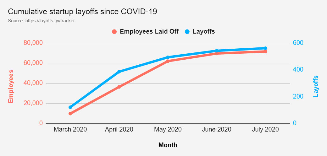
Die Pandemie hat die soziale Interaktion eingeschränkt:die Distanz. In Anbetracht dieses Risikofaktors befanden sich Länder auf der ganzen Welt in unterschiedlichen Quarantänen und viele Einkaufszentren mussten aufgrund deutlich gesunkener Verbraucherzahlen schließen . Dies hat zu sehr, sehr hohen Entlassungen geführt des Einkaufszentrumpersonals , sowie ähnliche wirtschaftliche Herausforderungen für Geschäftsinhaber .
Dies hat zum 2. Juli 2020 in den USA aufgrund von COVID-19 zu relativ niedrigem Einkommen (weniger als 40.000 US-Dollar Jahreseinkommen) zum Verlust von Arbeitsplätzen geführt. Unterkunft und Gastronomie sowie Einzelhandel und Unterhaltung machen zusammen etwa 4.000.000 der geschätzten verlorenen Arbeitsplätze aus.
Die wirtschaftliche Herausforderung, mit der verschiedene Branchen konfrontiert sind, in denen Lebensmittel, Konsumgüter und Einzelhandel in den Top-6-Branchen mit der höchsten Zahl an entlassenen Mitarbeitern (in Höhe von geschätzten über 20.000 Arbeitsplätzen) auftauchen. Unter der Annahme, dass „International“ alle in dieser Studie berücksichtigten Gebiete außerhalb der USA umfasst, erreicht die Gesamtzahl der weltweiten Entlassungen schätzungsweise 103.000+ Arbeitsplätze.
KOMPLIKATION
Angesichts der vorliegenden Daten hat das Team eine große Herausforderung darin gesehen, dass für die noch geöffneten Malls eine Risikounsicherheit hinsichtlich der Bevölkerungsdichte in verschiedenen Geschäften besteht. Abgesehen davon, obwohl das Tragen von Gesichtsmasken und das Vermeiden von Berührungen vielerorts Pflicht sind, kommt es immer noch zu Verstößen. Dies erschwert es den Mitarbeitern von Einkaufszentren und Geschäftsinhabern, die es sich nicht leisten können, aus der Ferne zu arbeiten, sich in diesem neuen normalen Arbeitsbereich sicher zurechtzufinden. Dies wirft die Frage auf:Wie können wir mit einer angemessenen Sicherheit garantieren, dass ein bestimmter Laden in der Mall zu jedem Zeitpunkt sicher ist?
Wir alle kämpfen jetzt gegen die vorherrschende COVID-19-Pandemie. Und außerdem sind wir jetzt in einer Situation, in der wir uns mit mehr Sicherheitsmaßnahmen an die vorherrschenden Bedingungen anpassen müssen. Während sich das Leben mit mehr Sicherheitsmaßnahmen zur Vermeidung einer Virusinfektion wieder normalisiert, herrscht auch in den Städten mehr Sicherheit auf öffentlichen Plätzen und in überfüllten Bereichen. Aber es gab viele Situationen, in denen wir die Sicherheitsmaßnahmen durchbrechen und mit einem unsicheren Element interagieren mussten, um den Bedürftigen zu helfen. Hier befasst sich das Projekt mit der Verhinderung der Verbreitung von COVID-19 durch Berührungsinteraktionen oder Berührungen.
Ein Experiment war durchgeführt worden, um die Ausbreitung eines Virus durch Berührung zu sehen. Die Ergebnisse wurden wie folgt ausgewertet:
Daher habe ich mich entschieden, die am häufigsten verwendeten Geräte in Wohnungen und Gesellschaften zu automatisieren, um eine freihändige Kommunikation mit Geräten zu gewährleisten.
Die folgenden Lösungen wurden bei der Herstellung dieses Prototyps entwickelt
- Intelligentes Intercom-System mit TinyML, das auf Arduino33 BLE Sense bereitgestellt wird: Das Folgende ist eine berührungslose Lösung, die Computer Vision und ein TinyML-Modell verwendet, um eine Person außerhalb der Tür zu erkennen und ein Klingeln durchzuführen, ohne dass die Person die Klingel berührt.
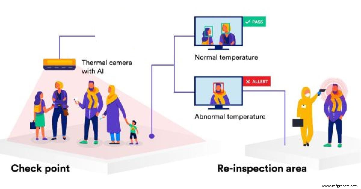
- Temperaturüberwachungssystem mit IoT und Warnsystem : Inmitten der Pandemie ist Sicherheit zu einem wichtigen Aspekt geworden. Daher verwendet das Temperaturüberwachungssystem das IoT-Thingspeak-Dashboard und erkennt Personen beim Betreten und misst deren Temperatur. Diese Temperatur wird für zeitnahe Trends und Datenanalysen in einem IoT-Dashboard angezeigt. Bei Erkennung einer abnormalen Temperatur werden Warnungen generiert, bei denen die Person einer zweiten Inspektion unterzogen wird.
- Berührungsfreies Aufzugssystem mit Spracherkennung TinyML-Modell auf Arduino BLE 33 sense: Wir fahren mehrmals täglich mit Aufzügen in einem Gebäude nach oben oder unten, und ich habe immer Angst, kontaminierte Schalter zu berühren, die von anderen Pendlern berührt wurden. Daher erkennt dieses Spracherkennungsmodell, wann eine Person nach oben oder unten gehen möchte, und führt die Aktion auf ähnliche Weise aus.
- MaskModel Detection System basierend auf TinyML und IoT-Überwachungssystem : Diese Methode verwendet ein Computer-Vision-Modell, das auf Arduino BLE 33 Sense bereitgestellt wird, um zu erkennen, ob eine Person eine Maske getragen hat oder nicht. Auf ähnliche Weise werden diese Daten an ein IoT-Dashboard gesendet, um sie zu überwachen und in unsicheren Zeiten Einschränkungen aufzuerlegen.
- Smart Queue-Überwachungs- und Einrichtungssystem in einem Supermarkt oder einem Einkaufszentrum mit TinyML, IoT und Computer Vision: Dieses Modell erkennt eine Person, die außerhalb des Supermarkts steht, und ermöglicht den gleichzeitigen Eintritt von 50 Personen in den Supermarkt. Es wird weitere 15 Minuten warten, bis die Leute im Inneren ihre Einkäufe erledigen und die nächsten 50 Personen wieder in die Mall dürfen. Dies geschieht mit Computer Vision und TinyML, die auf einem Arduino 33 BLE Sense bereitgestellt werden. Diese Daten werden dann an ein IoT-Dashboard projiziert, wo Echtzeitdaten verfolgt werden können.
- Personenüberwachungssystem in einem Gang in einem Einkaufszentrum und auf Kontamination basierendes Desinfektionssystem :Diese Lösung verwendet einen Personenerkennungsalgorithmus, der in einem Bereich in einem Einkaufszentrum oder einem Supermarkt eingesetzt wird, und wenn die Personenkontamination in einem Bereich den Schwellenwert überschritten hat, desinfiziert sie den Bereich selbst mit UV-Licht. Der Zeitraum und die Zeiten der Desinfektion werden auf einem IoT-Dashboard für das Supermarktpersonal zur Analyse projiziert.
Einrichten (Voraussetzungen für das Projekt):
Erforderliche Hardware:
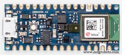
1)Arduino33BLE Sinn
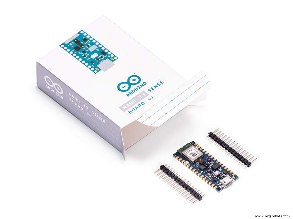
Der Arduino Nano 33 BLE Sense ist eine Weiterentwicklung des traditionellen Arduino Nano, verfügt jedoch über einen viel leistungsstärkeren Prozessor, den nRF52840 von Nordic Semiconductors, eine 32-Bit-ARM® Cortex™-M4-CPU mit 64 MHz. Auf diese Weise können Sie größere Programme als mit dem Arduino Uno (er hat 1 MB Programmspeicher, 32-mal größer) und mit viel mehr Variablen (der RAM ist 128-mal größer) erstellen. Der Hauptprozessor bietet weitere erstaunliche Funktionen wie Bluetooth®-Kopplung über NFC und Modi mit extrem niedrigem Stromverbrauch.
Eingebettete künstliche Intelligenz
Das Hauptmerkmal dieses Boards ist neben der beeindruckenden Auswahl an Sensoren die Möglichkeit, mit TinyML Edge-Computing-Anwendungen (KI) darauf auszuführen. Sie können Ihre Machine-Learning-Modelle mit TensorFlow™ Lite erstellen und sie mit der Arduino IDE auf Ihr Board hochladen.
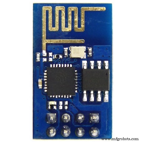
2)ESP8266 ESP-01
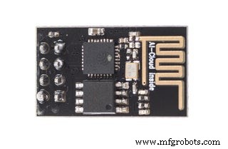
Der ESP8266 ESP-01 ist ein Wi-Fi-Modul, das Mikrocontroller ermöglicht Zugriff auf ein WLAN-Netzwerk . Dieses Modul ist ein in sich geschlossenes SOC (System On a Chip), das nicht unbedingt einen Mikrocontroller benötigt, um Ein- und Ausgänge zu manipulieren, wie Sie es normalerweise mit einem Arduino tun würden , zum Beispiel, weil der ESP-01 als kleiner Computer fungiert. Je nach Version des ESP8266 sind bis zu 9 GPIOs (General Purpose Input Output) möglich. So können wir einem Mikrocontroller einen Internetzugang geben, wie es der Wi-Fi-Schild dem Arduino tut, oder wir können den ESP8266 einfach so programmieren, dass er nicht nur Zugriff auf ein Wi-Fi-Netzwerk hat, sondern auch als Mikrocontroller agiert. Das macht den ESP8266 sehr vielseitig.
3)Arducam Mini 2MP plus
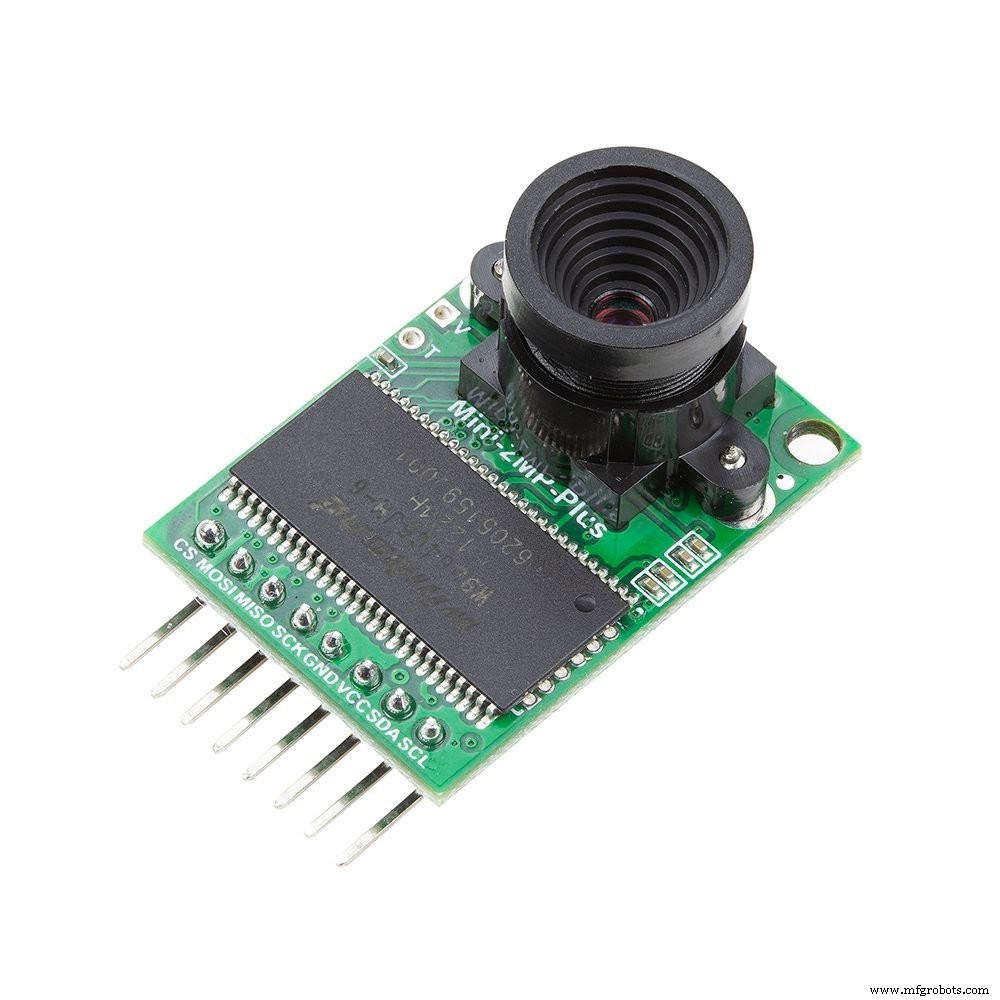
ArduCAM-2MP-Plus ist eine optimierte Version von ArduCAM Shield Rev.C und ist eine hochauflösende 2MP SPI-Kamera, die die Komplexität der Kamerasteuerungsschnittstelle reduziert. Es integriert den 2MP CMOS-Bildsensor OV2640 und bietet Miniaturgröße sowie die benutzerfreundliche Hardwareschnittstelle und die Open-Source-Codebibliothek.
Die ArduCAM mini kann auf allen Plattformen wie Arduino, Raspberry Pi, Maple, Chipkit, Beaglebone black verwendet werden, solange sie über SPI- und I2C-Schnittstellen verfügen und sich gut mit Standard-Arduino-Boards verbinden lassen. ArduCAM mini bietet nicht nur die Möglichkeit, eine Kameraschnittstelle hinzuzufügen, die in einigen kostengünstigen Mikrocontrollern nicht vorhanden ist, sondern bietet auch die Möglichkeit, mehrere Kameras zu einem einzigen Mikrocontroller hinzuzufügen.
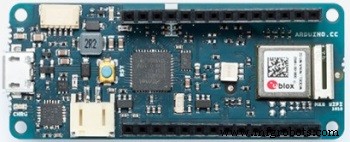
4) Arduino MKR WiFi 1010:
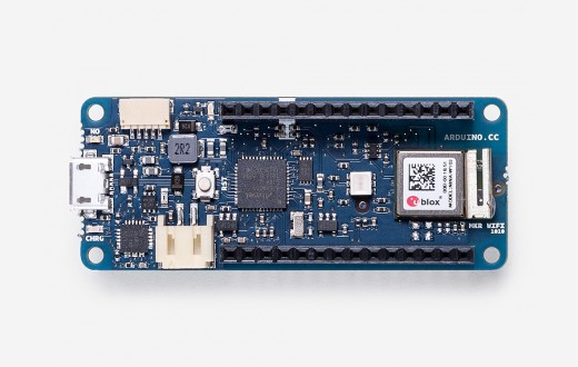
Der Arduino MKR WiFi 1010 ist der einfachste Einstiegspunkt in das grundlegende IoT- und Pico-Netzwerk-Anwendungsdesign. Egal, ob Sie ein Sensornetzwerk aufbauen möchten, das mit Ihrem Büro- oder Heimrouter verbunden ist, oder ein BLE-Gerät erstellen möchten, das Daten an ein Mobiltelefon sendet, das MKR WiFi 1010 ist Ihre One-Stop-Lösung für viele der grundlegenden IoT-Anwendungen Szenarien.
Der Hauptprozessor des Boards ist ein stromsparender Arm® Cortex®-M0 32-Bit SAMD21, wie in den anderen Boards der Arduino MKR-Familie. Die WiFi- und Bluetooth®-Konnektivität erfolgt mit einem Modul von u-blox, dem NINA-W10, einem Low-Power-Chipsatz, der im 2,4-GHz-Bereich arbeitet. Darüber hinaus wird eine sichere Kommunikation durch den Microchip® ECC508-Kryptochip gewährleistet. Außerdem finden Sie ein Batterieladegerät und eine ansteuerbare RGB-LED an Bord.
Softwaretools:
1)Arduino Web Editor
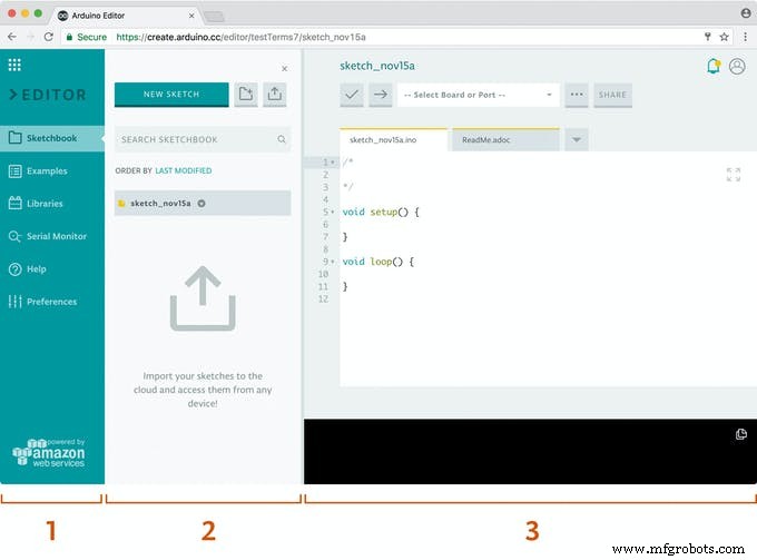
Arduino Create ist eine integrierte Online-Plattform, die es Makern und professionellen Entwicklern ermöglicht, Code zu schreiben, auf Inhalte zuzugreifen, Boards zu konfigurieren und Projekte zu teilen. Gehen Sie schneller als je zuvor von einer Idee zum fertigen IoT-Projekt. Mit Arduino Create können Sie eine Online-IDE verwenden, mehrere Geräte mit der Arduino IoT Cloud verbinden, eine Sammlung von Projekten auf Arduino Project Hub durchsuchen und mit dem Arduino Device Manager eine Remote-Verbindung zu Ihren Boards herstellen. Außerdem können Sie Ihre Kreationen zusammen mit Schritt-für-Schritt-Anleitungen, Schaltplänen und Referenzen teilen und Feedback von anderen erhalten.
2) Edge Impulse Studio:
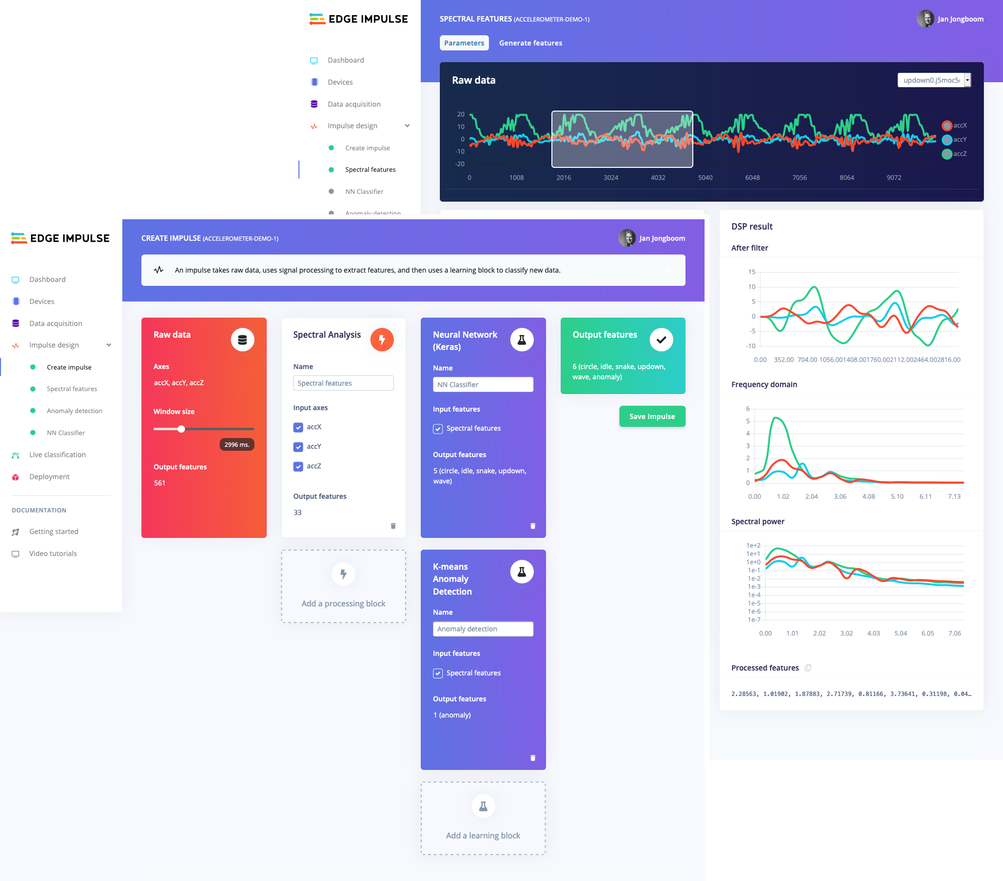
Der Trend, ML auf Mikrocontrollern auszuführen, wird manchmal als Embedded ML oder Tiny ML bezeichnet. TinyML hat das Potenzial, kleine Geräte zu entwickeln, die intelligente Entscheidungen treffen können, ohne Daten in die Cloud senden zu müssen – großartig aus Effizienz- und Datenschutzsicht. Sogar leistungsfähige Deep-Learning-Modelle (basierend auf künstlichen neuronalen Netzen) erreichen mittlerweile Mikrocontroller. Im vergangenen Jahr wurden durch Projekte wie TensorFlow Lite für Mikrocontroller, uTensor und Arms CMSIS-NN große Fortschritte erzielt, um Deep-Learning-Modelle kleiner, schneller und auf Embedded-Hardware lauffähig zu machen; Aber das Erstellen eines hochwertigen Datasets, das Extrahieren der richtigen Funktionen, das Trainieren und Bereitstellen dieser Modelle kann immer noch kompliziert sein.
Mit Edge Impulse können Sie jetzt schnell reale Sensordaten sammeln, ML-Modelle auf diesen Daten in der Cloud trainieren und das Modell dann wieder auf Ihrem Arduino-Gerät bereitstellen. Von dort aus können Sie das Modell mit einem einzigen Funktionsaufruf in Ihre Arduino-Skizzen integrieren. Ihre Sensoren sind dann viel intelligenter und können komplexe Ereignisse in der realen Welt verstehen. Mit den integrierten Beispielen können Sie Daten vom Beschleunigungsmesser und dem Mikrofon sammeln, aber es ist einfach, andere Sensoren mit wenigen Codezeilen zu integrieren.
3) Dingspeak:
ThingSpeak™ ist ein IoT-Analysedienst, mit dem Sie Live-Datenströme in der Cloud aggregieren, visualisieren und analysieren können. ThingSpeak bietet sofortige Visualisierungen von Daten, die von Ihren Geräten an ThingSpeak gesendet werden. Mit der Möglichkeit, MATLAB®-Code in ThingSpeak auszuführen, können Sie Online-Analysen durchführen und eingehende Daten verarbeiten. ThingSpeak wird häufig für Prototyping und Proof-of-Concept-IoT-Systeme verwendet, die Analysen erfordern.
Sie können Daten von jedem mit dem Internet verbundenen Gerät mithilfe einer Rest-API oder MQTT direkt an ThingSpeak senden. Darüber hinaus ermöglichen Cloud-to-Cloud-Integrationen mit The Things Network, Senet, dem Libelium Meshlium Gateway und Particle.io Sensordaten, ThingSpeak über LoRaWAN®- und 4G/3G-Mobilfunkverbindungen zu erreichen.
Erste Schritte mit Implementierungen:
1. Projekt:Berührungsloses Aufzugssystem mit Spracherkennung TinyML-Modell auf Arduino BLE 33 sense:
Beim Pendeln benutzen wir mehrmals täglich Aufzüge! Ein häufig verwendeter Schalter wird von all denen verunreinigt, die den Aufzug schon früher berührt haben. Also habe ich beschlossen, eine berührungslose Lösung für Aufzüge zu entwickeln, die Sprachbefehle verwendet und ohne die Verwendung von IoT oder Wifi-Netzwerk zusammenarbeitet und die Aktion ausführt. Es wurden Lösungen von berührungslosen Aufzugssystemen implementiert, die Gestensteuerung oder Ultraschallsensoren verwenden, um Operationen auszuführen, aber das Problem bei diesen Sensoren besteht darin, dass sie aus einer geringeren Entfernung aktiviert werden müssen und somit die Berührungsgefahr erhöht wird. Außerdem sind diese Sensoren hochsensibel und werden selbst dann aktiviert, wenn kleine Gegenstände im Weg sind und sie aktivieren. Dementsprechend schlug ich vor, eine genauere Lösung mit Spracherkennung auf dem Arduino 33 BLE Sense zu schaffen. Dieses Modell akzeptiert zwei Befehle, entweder "up" oder "down" und sendet dementsprechend Daten an das Servo, um die entsprechenden Tasten am Schalter zu drücken. Die Idee, die Daten an Servos zu senden, um Schalter zu aktivieren, liegt darin begründet, dass die Mehrheit der Gesellschaften vorgefertigte Schalter- und Anzeigesysteme haben und diese bereits vorhandenen Systeme daher nicht behindern. Dies wird geschaffen, um ein externes Hardwaresystem hinzuzufügen, um die Funktionen zu steuern.
Die zur Ausführung dieser Funktion verwendete Kernlogik ist:
Training des Modells zum Interpretieren von "Auf"- und "Sprache"-Befehlen in Edge Impulse Studio
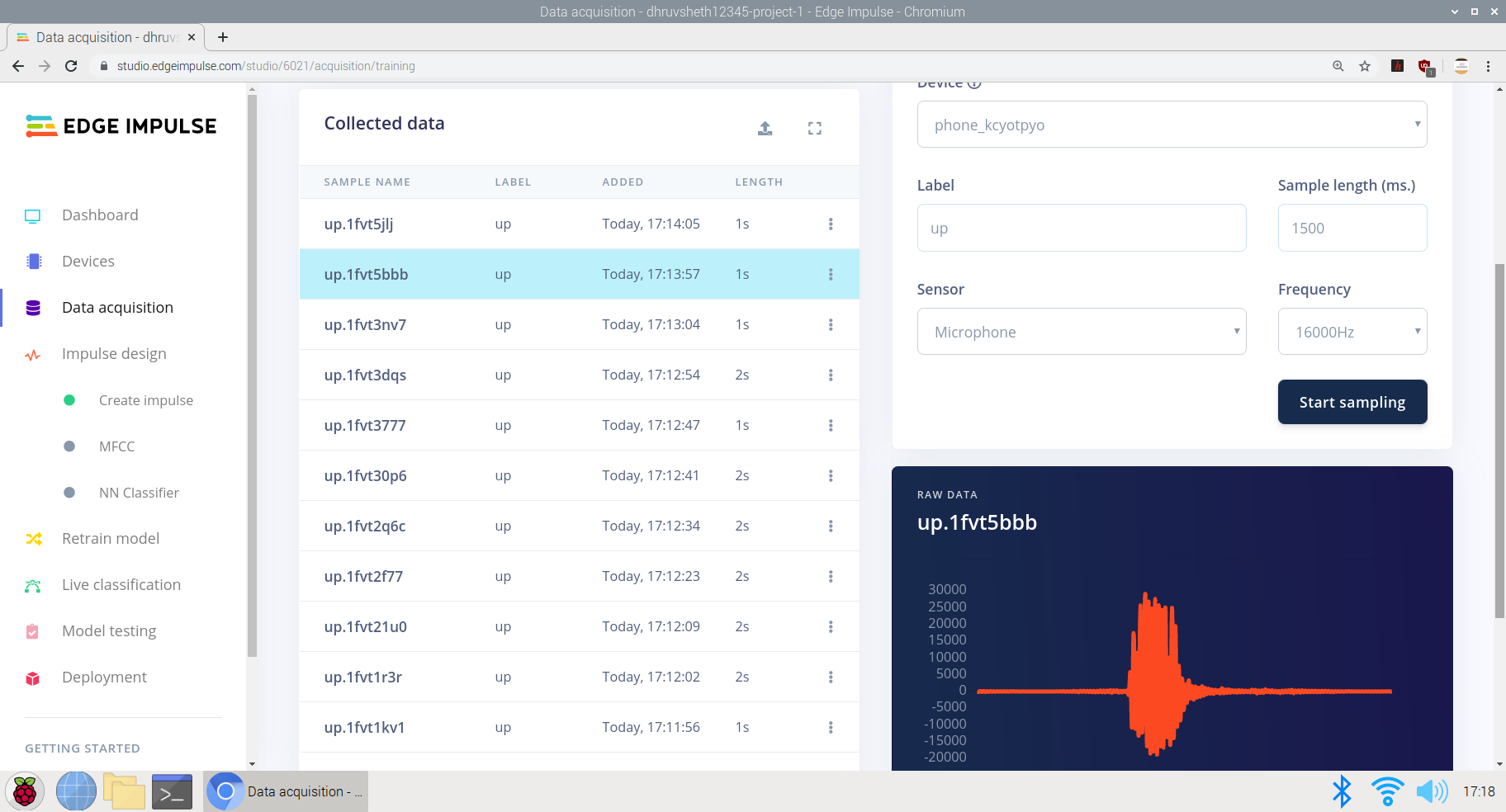
a) Akkumulieren von Rohdaten mit Trainings- und Testdatensätzen. Hier habe ich Daten von 1:30min mit jeder Datendauer von "up" und "down" von 2sec angesammelt.
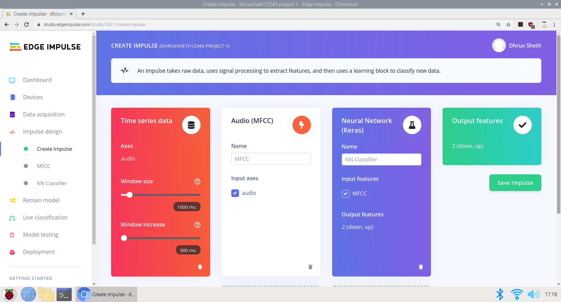
b) Erstellen eines Impulses basierend auf den erforderlichen Parametern:
Hier habe ich die Fensterinkrementgröße auf 300 ms eingestellt und das Training basiert auf dem Keras Neural Network, das für Mikrofon- und Beschleunigungsmesserdaten bestimmt ist.
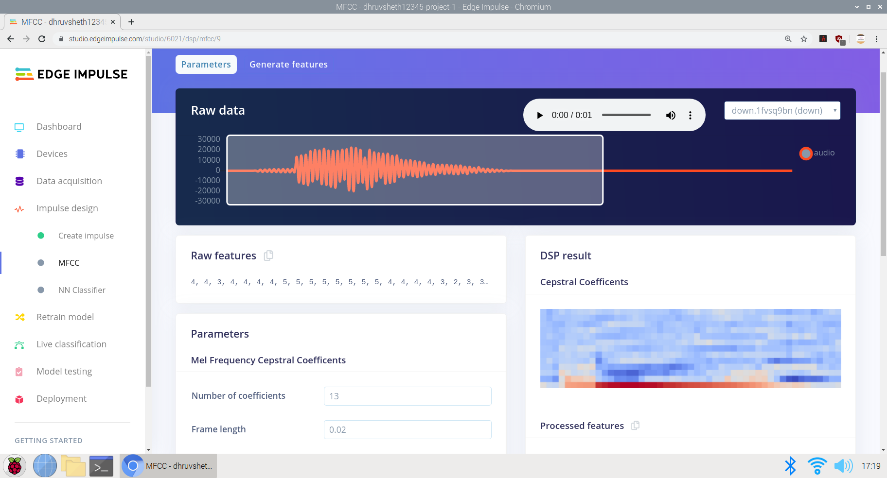
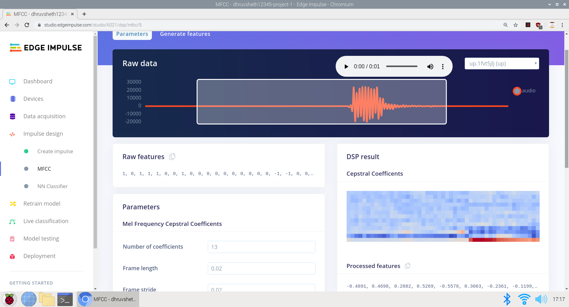
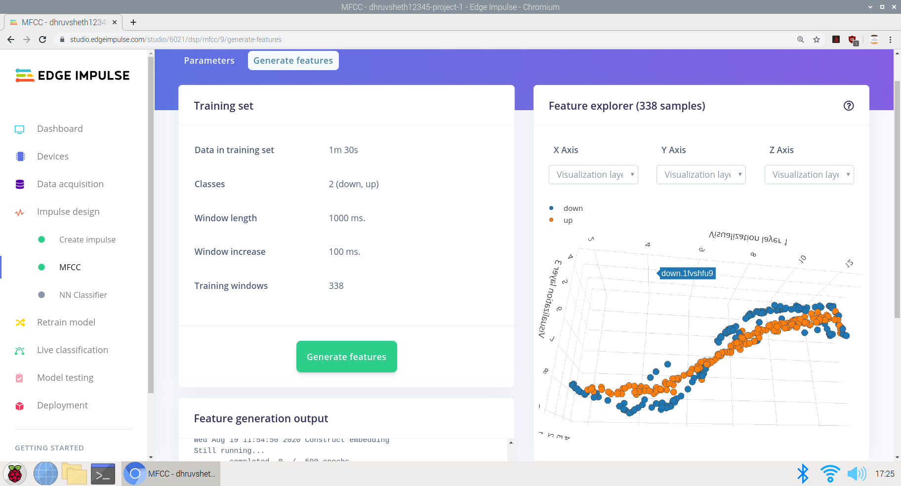
c) Umwandlung von Rohdaten in verarbeitete Daten. Direkt unter den Rohdaten können wir die Rohdatenmerkmale sehen und die verarbeiteten Daten werden als DSP-Ergebnisse basierend auf Cepstralkoeffizienten angesehen.
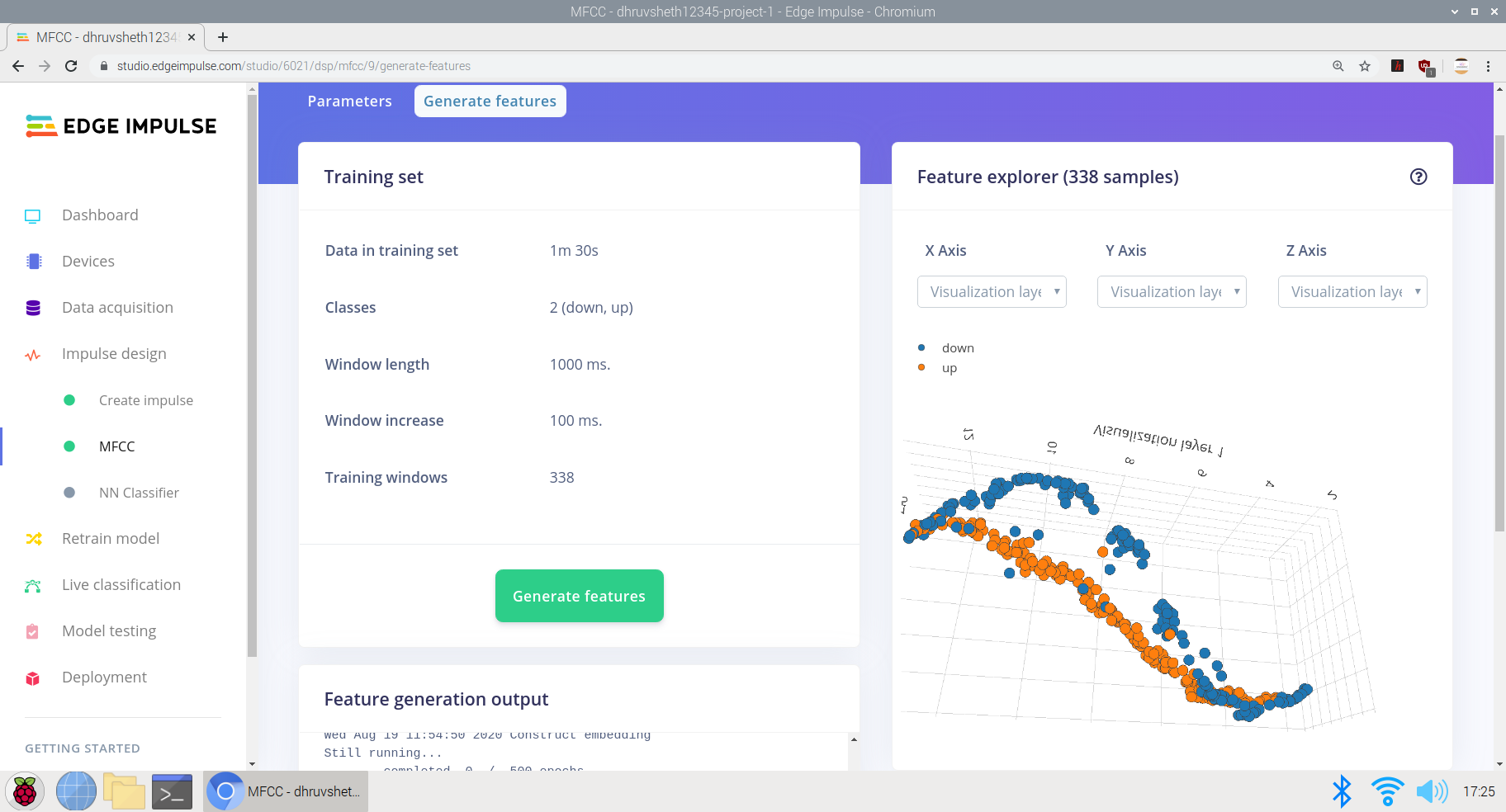
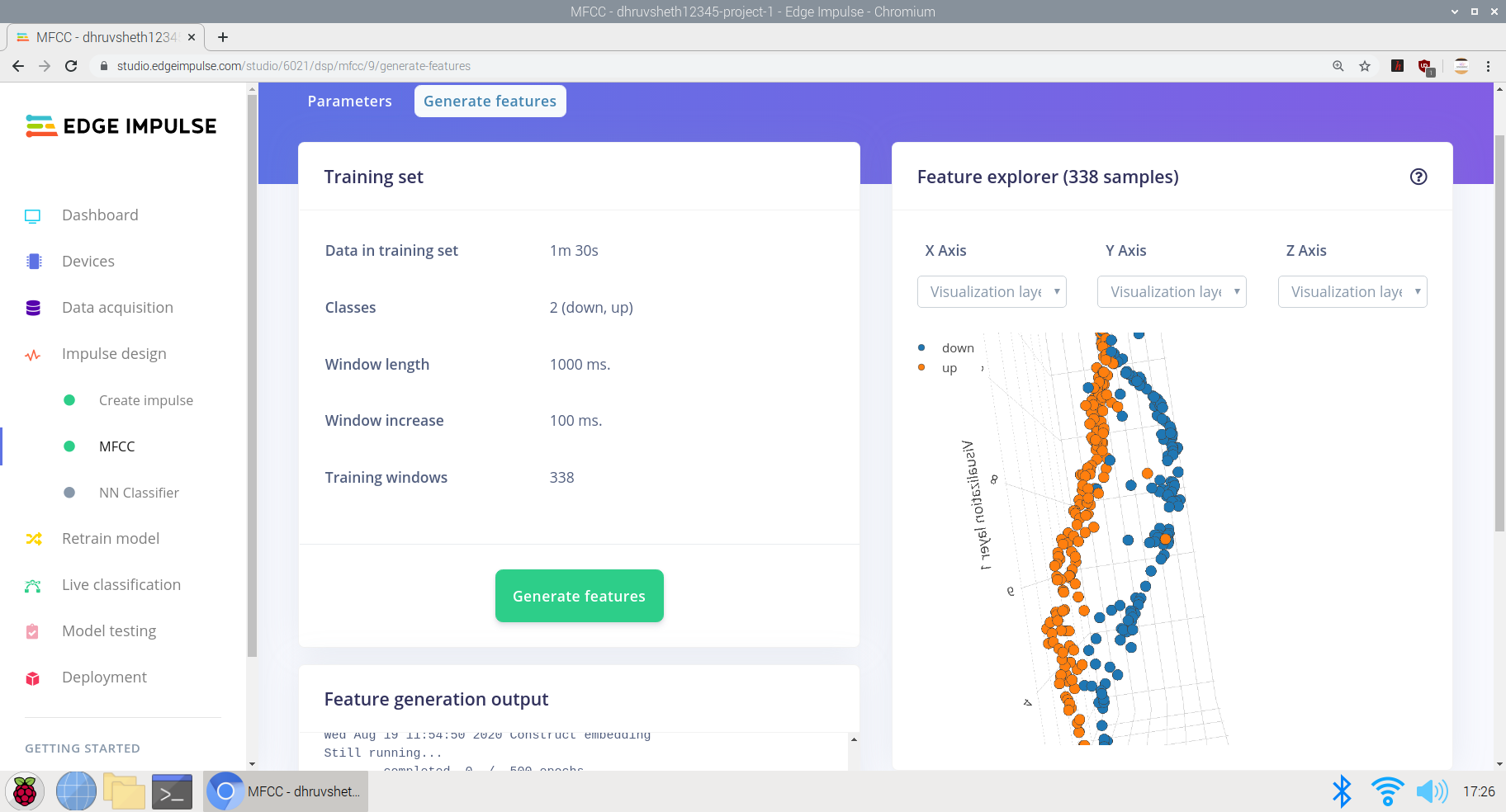
d) Trainieren der Eingabedaten, um verarbeitete Features zu generieren. Ich habe die Daten mit niedriger und hoher Frequenz basierend auf denselben Daten aufgezeichnet, um den Impuls besser zu trainieren und die Spracherkennung präzise zu trainieren, basierend auf allen Arten von Stimmen. Hier erhalten wir eine Feature-Ausgabe in einer "S"-Kurve mit zentraler Differenzierung auf der x-, y- und z-Achse.
e) Schließlich Entwerfen einer neuronalen Netzwerkarchitektur im Edge-Impuls-Neuralnetzwerk-Klassifikator und Trainieren des Netzwerks.
Hier ist die für die Dateneingabe entworfene neuronale Netzwerkarchitektur wie folgt:
- Eingabeebene
- Ebene umformen
- 1D-Convo-Pool-Schicht (30 Neuronen, 5 Kernel)
- 1D-Convo-Pool-Schicht (10 Neuronen, 5 Kernel)
- Ebene glätten
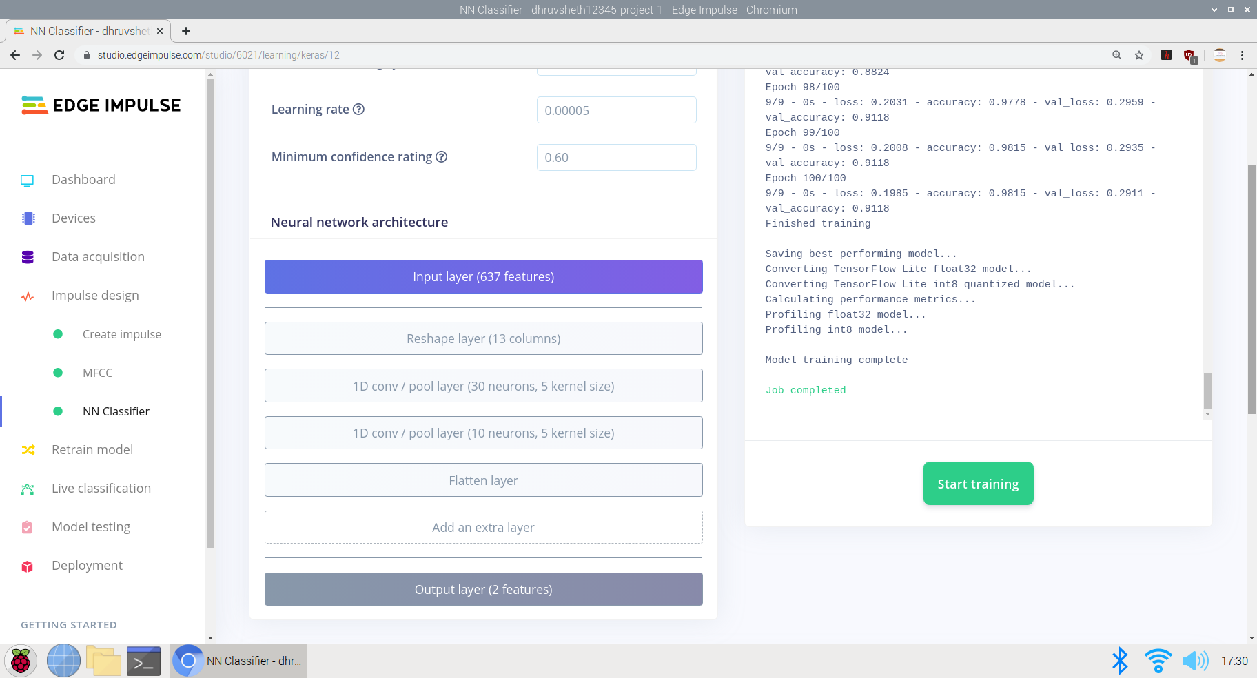
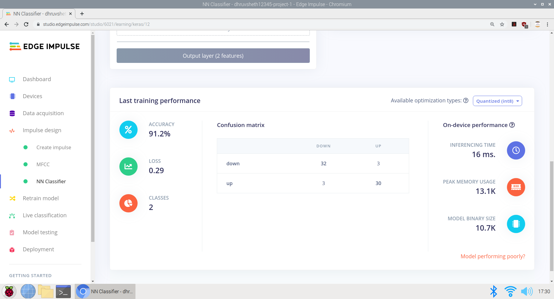
Das Modell schnitt mit einer durchschnittlichen Genauigkeit von 91,2% und einem Verlust von 0,29 ziemlich gut ab. Das Modell wurde auf 100 Trainingszyklen (Epochen) trainiert. Die Verwirrungsmatrix sieht ziemlich klar und genau aus, wobei die meisten Restdaten mit ihren jeweiligen beschrifteten Klassen übereinstimmen.
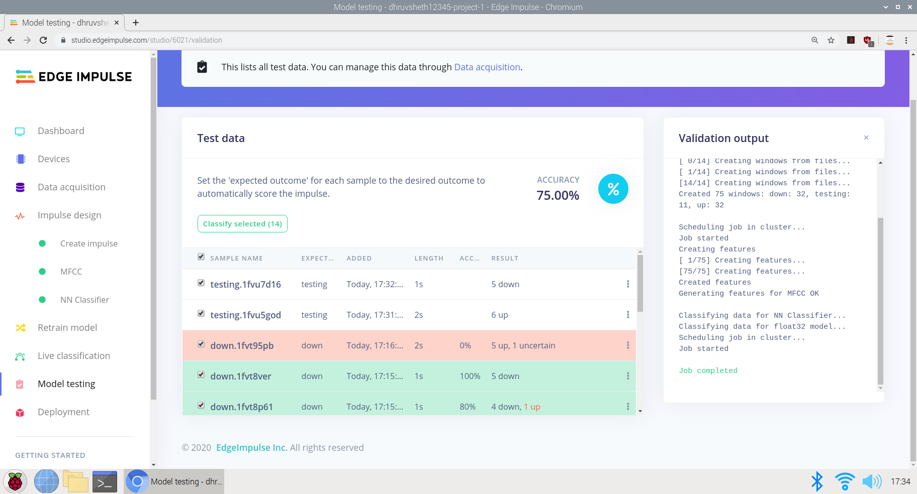
Nachdem das Modell trainiert war, testete ich das Modell mit Testdaten und Live-Daten und das Modell erreichte eine Genauigkeit von 75% basierend auf 24 Sekunden Testdaten

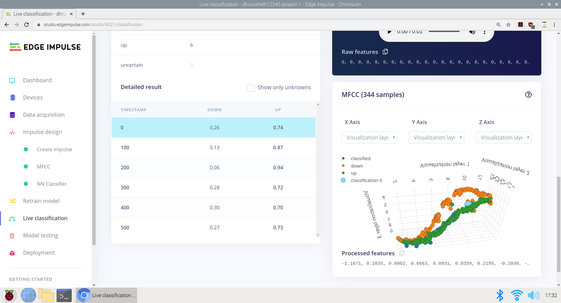
Nachdem das Modell schließlich trainiert war und eine anständige Genauigkeit mit der Logik erreicht hatte, stellte ich das Modell als Arduino-Bibliothek bereit und stellte es auf Arduino 33 BLE Sense bereit.
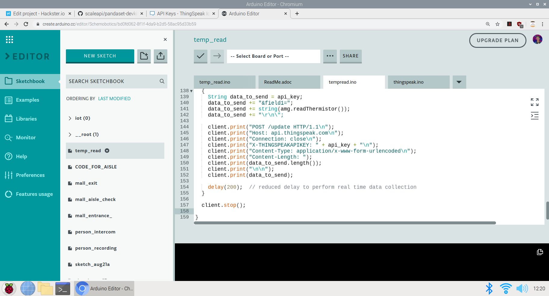
Nachdem das Skript fertig war, begann ich, es im Arduino Web Editor zu bearbeiten, um die Anpassung zu erleichtern, und die endgültige Skriptausgabe, die auf Arduino 33 BLE Sense bereitgestellt werden könnte, lautet wie folgt:
Sie können die Datei main.ino auf der Arduino Web Editor-Plattform hier sehen:
Main-script.ino - Arduino Web-Editor
Main-script.ino - Github
Bereitstellung auf Arduino 33 BLE Sense
Zum jetzigen Zeitpunkt ist das einzige Arduino-Board mit eingebautem Mikrofon das Arduino Nano 33 BLE Sense, also verwenden wir dieses für diesen Abschnitt. Wenn Sie ein anderes Arduino-Board verwenden und Ihr eigenes Mikrofon anschließen, müssen Sie Folgendes implementieren
Zum jetzigen Zeitpunkt ist das einzige Arduino-Board mit eingebautem Mikrofon das Arduino Nano 33 BLE Sense, also verwenden wir dieses für diesen Abschnitt.
Der Arduino Nano 33 BLE Sense hat auch eine eingebaute LED, die wir verwenden, um anzuzeigen, dass ein Wort erkannt wurde und auch das Servo zu steuern, um die Funktion auszuführen
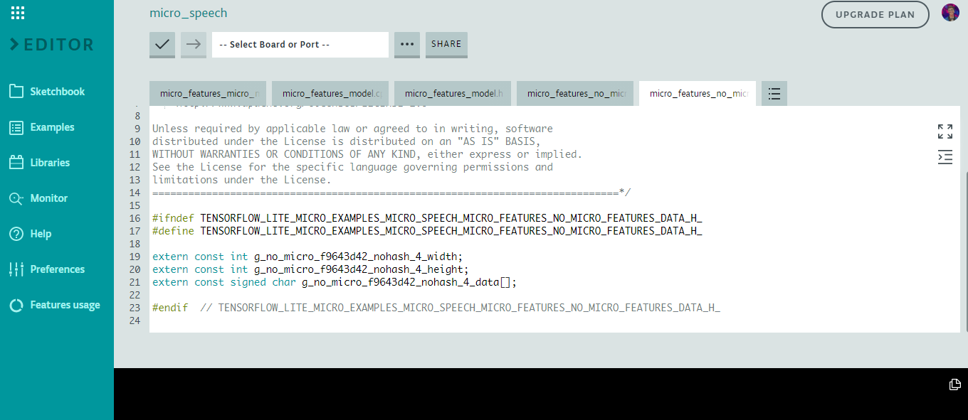
Hier ist ein Ausschnitt des Mikrofeature-Codes im Modell
Die Logik funktioniert wie folgt für die Antwort auf den Befehl:
// Wenn wir einen Befehl hören, leuchten Sie die entsprechende LED auf und schalten Sie das entsprechende Servo ein
if (found_command[0] =='up') {
last_command_time =current_time;
digitalWrite(LEDG, LOW); // Grün für oben, Einschalten der LED durch LOW-Befehl
servo_7.write(0); // Servo auf 0 Grad drehen, um auf die Taste am Lift zu klicken, wenn "oben" gesagt wird
verzögerung (100);
digitalWrite (LEDG, HIGH); // Ausschalten der LED nach dem Blinken des Befehls
servo_7.write(180); // Servo kehrt in seine ursprüngliche Position zurück, dh 180 Grad
}
 // Wenn wir einen Befehl hören, leuchten Sie die entsprechende LED auf und schalten Sie das entsprechende Servo ein
if (found_command[0] =='down') {
last_command_time =current_time;
digitalWrite(LEDG, LOW); // Grün für oben, Einschalten der LED durch LOW-Befehl
servo_7.write(0); // Servo auf 0 Grad drehen, um auf die Taste am Lift zu klicken, wenn "unten" gesagt wird
verzögerung (100);
digitalWrite (LEDG, HIGH); // Ausschalten der LED nach dem Blinken des Befehls
servo_7.write(180); // Servo kehrt in seine ursprüngliche Position zurück, dh 180 Grad
}
Die zweite Befehlsantwort ist die gleiche wie oben, aber dreht den Servo, wenn der Befehl "unten" gehört wird.
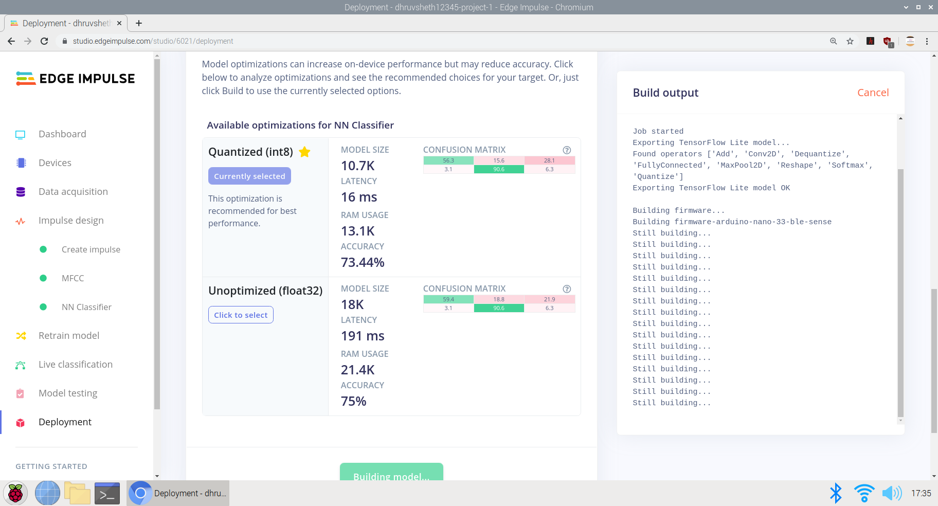
Nach dem Training von Daten erhalten wir eine trainierte Tflite-Dataset-Ausgabe wie folgt:
Hier verwenden wir das eingebaute Mikrofon des Arduino Nano 33 BLE Sense und das Modell verwendet durchschnittlich ~ 24-28 KB aus dem 256 KB Flash-Speicher auf dem Arduino Nano Board. Dieses Modell ist im Vergleich zum Bilderkennungsmodell vergleichsweise leicht und kann Informationen mit einer viel höheren Geschwindigkeit verarbeiten.
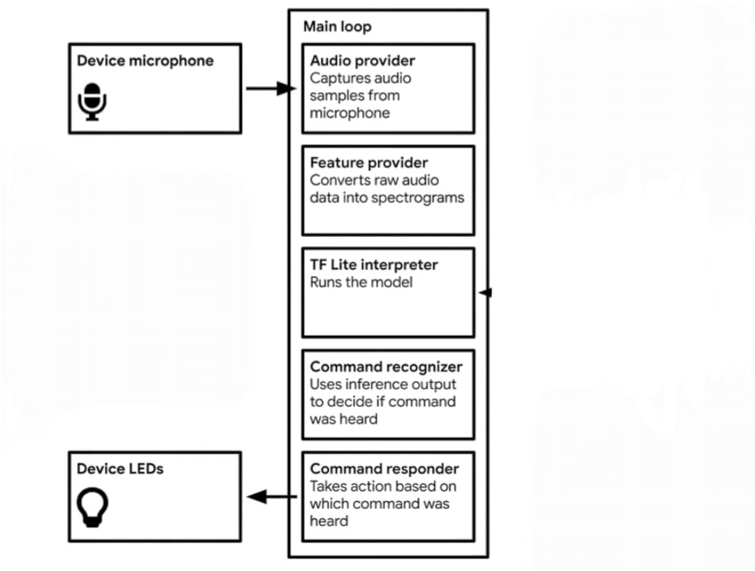
Die Logik im Spracherkennungsmodell geht wie folgt:
Daten werden erfasstErfasst Audiobeispiele vom MikrofonKonvertiert Audio-Rohdaten in SpektrogrammeTflite-Interpreter führt das Modell ausVerwendet die Inferenzausgabe, um zu entscheiden, ob der Befehl gehört wurdeWenn der Abwärtsbefehl zu hören ist, bewegt sich der Servo durch Drücken der Abwärtstaste auf dem Hubbedienfeld.Wenn der Aufwärtsbefehl zu hören ist, bewegt sich das Servo durch Drücken der Aufwärtstaste im Hubbedienfeld.
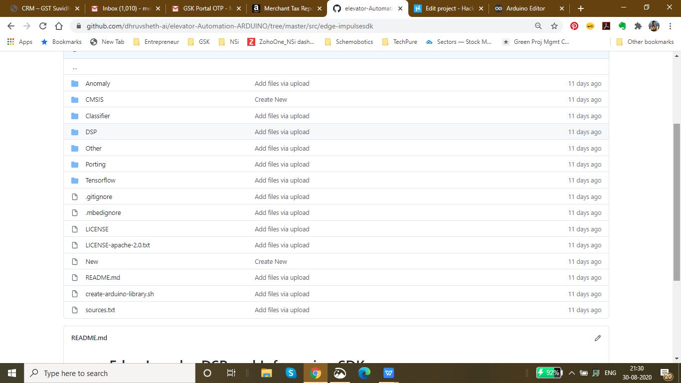
Der oben sind die Daten in der Bibliothek des trainierten Modells. Die Hauptfunktionen sind in der Tensorflow-Datei enthalten.
Schaltplan für das Projekt:

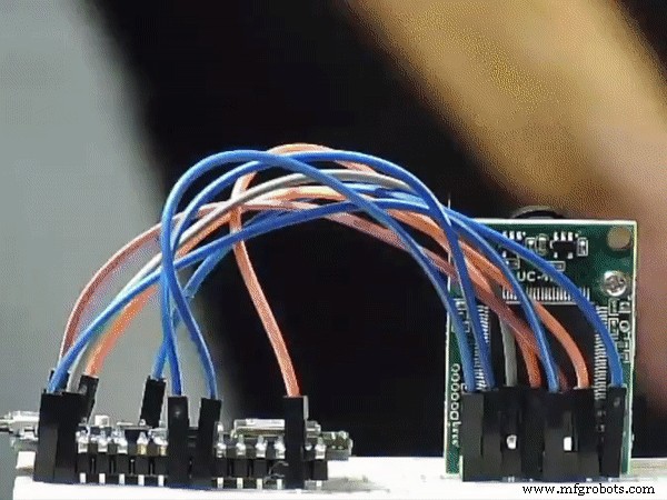
Der Arduino Nano 33 BLE Sense nutzt das eingebaute Mikrofon zum Sammeln von Rohdaten. Da die Inferenz auf Arduino Zeit braucht, habe ich eine Verzögerung von 100 Millisekunden hinzugefügt, um die Daten genau zu verarbeiten. Daher blinkt zwischen zwei Aufnahme-Samples eine eingebaute blaue LED, die die zwischen den beiden LED-Blitzen zu hörende/zu sagende Reaktion anzeigt.

Dies ist eine Simulation des Arduino 33 BLE Sense, die das Blinken der LED zwischen zwei erfolgreichen Mikrofoneingangsintervallen zeigt
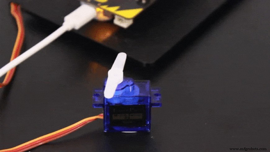
Basierend auf der Befehlseingabe dreht sich das Servo entsprechend
Jetzt gibt es andere Alternativen zu einem berührungslosen Aufzugsautomatisierungssystem wie die Verwendung von Ultraschallsensoren oder Gestensensoren, aber beide haben ihre eigenen Mängel, daher habe ich mich entschieden, das sprachgesteuerte Aufzugsautomatisierungssystem zu entwickeln
Fehler bei Ultraschallsensoren: Ultraschallsensoren sind sehr bewegungsempfindlich. Kommt ein sich im Durchgang bewegendes Objekt in den Bereich der Ultraschallsensoren, werden diese aktiviert. Ultraschallsensoren sind auch nicht genau genug, manchmal verarbeiten diese falsche Informationen.
Fehler bei gestengesteuerten Sensoren: Diese Sensoren sind genauer als Ultraschallsensoren, müssen jedoch aus einer geringeren Entfernung aktiviert werden. Dies erhöht das Berührungsrisiko zwischen den Händen und der Hebebühne.
Die sprachgesteuerte Aufzugssteuerung ist jedoch genauer als die beiden oben genannten Lösungen und kann aus größerer Entfernung als der Ultraschall- und Gestensensor aktiviert werden.
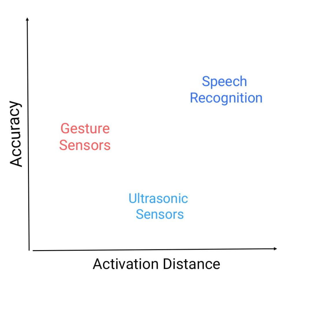
Hier ist ein Diagramm der Genauigkeit im Vergleich zur Aktivierungsentfernung und wo diese Sensoren stehen.
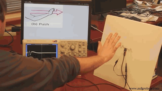
Hier wird die Entfernung angezeigt, die benötigt wird, um den Gestensensor zu aktivieren. Da dieser Abstand als wirklich geringer angesehen wird, ist die Kontaminationsrate hoch
Als nächstes gehen wir zum zweiten Teilprojektteil des Hauptprojekts über
2. Projekt:Intelligentes Intercom-System mit Gesichtserkennung und TinyML:
CDC hat seine Website aktualisiert und eine Pressemitteilung herausgegeben, in der es heißt, dass der indirekte Kontakt von einer mit dem neuen Coronavirus kontaminierten Oberfläche – bekannt als fomite Übertragung – ein möglicher Weg ist, sich mit dem neuen Coronavirus zu infizieren.
Untersuchungen haben ergeben, dass das neue Coronavirus auf Kunststoff- und Metalloberflächen sowie auf Karton 24 Stunden lang bis zu drei Tage andauern kann. Es gibt jedoch viele Dinge, die passieren müssen, damit sich eine Person durch Berühren einer kontaminierten Oberfläche mit Covid-19 infiziert.
Zunächst muss eine Person mit genügend Virus in Kontakt kommen, um tatsächlich eine Infektion auszulösen. Um sich beispielsweise mit dem Influenzavirus zu infizieren, müssen Millionen von Kopien des Virus von einer Oberfläche in das Gesicht einer Person gelangen, aber es sind nur wenige Tausend Kopien erforderlich, wenn das Virus direkt in die Lunge gelangt, das New York Zeiten Berichte.
Wenn eine Person zufällig eine Oberfläche mit großen Spuren des Virus berührt, muss sie genug von dem Virus aufnehmen und dann ihre Augen, Nase oder ihren Mund berühren – weshalb Experten des öffentlichen Gesundheitswesens sagen, dass es so wichtig ist, Berührungen zu vermeiden Oberflächen zu oft und hindern Sie daran, kontaminierte oder häufig berührte Gegenstände zu berühren.
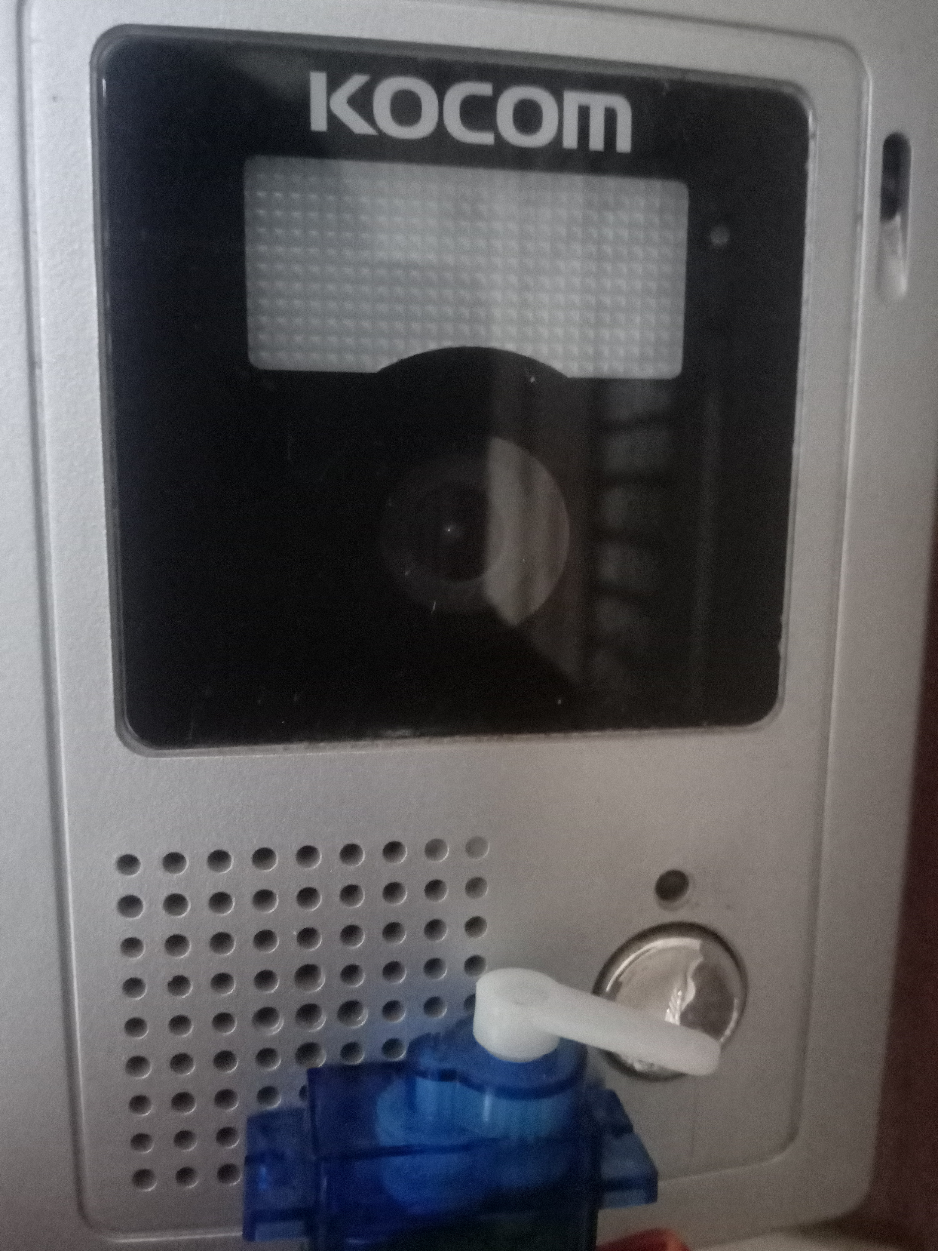
Das COVID-19-Virus verbreitet sich auf der ganzen Welt. Selbst wenn es endlich nachlässt, werden die Menschen eine Sensibilität dafür entwickelt haben, Dinge in der Öffentlichkeit zu berühren. Da die meisten Sprechanlagen so konzipiert sind, dass zum Tätigen eines Anrufs eine Taste gedrückt werden muss, habe ich beschlossen, dass berührungslose Sprechanlagenlösungen benötigt werden, bei denen die Personen nichts berühren müssen.
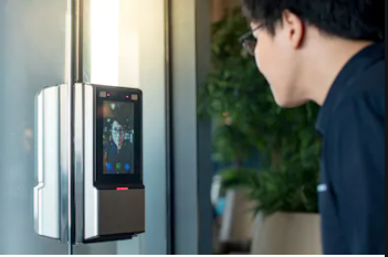
Das obige Bild zeigt ein implementiertes Gegensprechsystem auf Gesichtserkennungsbasis.
Um das Problem berührungsbasierter Systeme zu lösen, ist es notwendig, die Berührungs- und Berührungsstellen zu reduzieren. In traditionellen Intercom-Systemen bestehen sie aus schalterbasierten Systemen, bei deren Betätigung die Klingel klingelt. Um das berührungsbasierte System zu überarbeiten, das das Risiko einer Kontamination von Oberflächen erhöht, habe ich mich entschieden, ein berührungsloses Gesichtserkennungssystem zu entwickeln, das auf dem Arduino 33 BLE Sense basierend auf tinyML und Tensorflow Lite eingesetzt wird.
In diesem intelligenten Intercom-System habe ich den auf Arduino 33 BLE Sense eingesetzten Personenerkennungsalgorithmus verwendet, der Personen identifiziert und dementsprechend die Glocke mit einer LED-Matrix-Anzeige läutet, die "Person" anzeigt.
Auf dem Weg zur Implementierung des Smart Intercom Systems:
Die folgenden Softwares wurden bei der Entwicklung dieses Modells verwendet:
- TensorFlow lite
- Arduino Web Editor
In this person detection model, I have used the Pre-trained TensorFlow Person detection model apt for the project. This pre-trained model consists of three classes out of which the third class is with undefined set of data:
"unused",
"person",
"notperson"
In our model we have the Arducam Mini 2mp plus to carry out image intake and this image data with a decent rate of fps is sent to the Arduino Nano 33 BLE Sense for processing and and classification. Since the Microcontroller is capable of providing 256kb RAM, we change the image size of each image to a standard 96*96 for processing and classification. The Arduino Tensorflow Lite network consists of a deep learning framework as:
- Depthwise Conv_2D
- Conv_2D
- AVERAGE Pool_2D
- Flatten layer
This deep learning framework is used to train the Person detection model.
The following is the most important function defined while processing outputs on the Microcontroller via Arduino_detetction_responder.cpp
// Process the inference results.
 uint8_t person_score =output->data.uint8[kPersonIndex];
 uint8_t no_person_score =output->data.uint8[kNotAPersonIndex];
 RespondToDetection(error_reporter, person_score, no_person_score);
In the following function defining, the person_score , the no_person_score have been defined on the rate of classification of the data.
The Logic works in the Following way:
├── Autonomous Intercom System
├── Arducam Mini 2mp plus
│ ├── Visual data sent to Arduino
├── Arduino 33 BLE Sense
│ ├── if person-score> no_person_score
│ │ ├── Activate the buzzer
│ │ ├── Display "Person" on the LED Matrix
│ │ └── ...Repeat the loop
Adhering to the above logic, The arducam Mini 2mp plus continuously takes in visual data and sends this data to the Arduino 33 BLE Sense to process and classify the the data collected. Once the raw data is converted to processed data, it is then classified as per the data trained. If a person is detected, the Arduino sends a signal to the buzzer to activate and the MAX7219 to display "person". In this way, the logic of the system works.
Functioning and Working of Logic in Code:
The following are the Libraries included in themain.ino code for functioning of the model.
#include

#include "main_functions.h"

#include "detection_responder.h"
#include "image_provider.h"
#include "model_settings.h"
#include "person_detect_model_data.h"
#include "tensorflow/lite/micro/kernels/micro_ops.h"
#include "tensorflow/lite/micro/micro_error_reporter.h"
#include "tensorflow/lite/micro/micro_interpreter.h"
#include "tensorflow/lite/micro/micro_mutable_op_resolver.h"
#include "tensorflow/lite/schema/schema_generated.h"
#include "tensorflow/lite/version.h"
In the following code snippet, the loop is defined and performed. Since this is the main.ino code, it controls the core functioning of the model - used to run the libraries in the model.
void loop() {
 // Get image from provider.
 if (kTfLiteOk !=GetImage(error_reporter, kNumCols, kNumRows, kNumChannels,
 input->data.uint8)) {
 TF_LITE_REPORT_ERROR(error_reporter, "Image capture failed.");
 }

 // Run the model on this input and make sure it succeeds.
 if (kTfLiteOk !=interpreter->Invoke()) {
 TF_LITE_REPORT_ERROR(error_reporter, "Invoke failed.");
 }

 TfLiteTensor* output =interpreter->output(0);

 // Process the inference results.
 uint8_t person_score =output->data.uint8[kPersonIndex];
 uint8_t no_person_score =output->data.uint8[kNotAPersonIndex];
 RespondToDetection(error_reporter, person_score, no_person_score);
}
In the following code snippet, the necessary libraries required to inference the image to be captured is displayed. The images after captured are converted to a 96*96 standardised size which can be interpreted on the arduino board.
Here, the Arducam mini 2mp OV2640 library has been utilised.
This code has been provided in the arduino_image_provider.cpp snippet
#if defined(ARDUINO) &&!defined(ARDUINO_ARDUINO_NANO33BLE)
#define ARDUINO_EXCLUDE_CODE
#endif // defined(ARDUINO) &&!defined(ARDUINO_ARDUINO_NANO33BLE)

#ifndef ARDUINO_EXCLUDE_CODE

// Required by Arducam library
#include
#include
#include
// Arducam library
#include
// JPEGDecoder library
#include

// Checks that the Arducam library has been correctly configured
#if !(defined OV2640_MINI_2MP_PLUS)
#error Please select the hardware platform and camera module in the Arduino/libraries/ArduCAM/memorysaver.h
#endif

// The size of our temporary buffer for holding
// JPEG data received from the Arducam module
#define MAX_JPEG_BYTES 4096
// The pin connected to the Arducam Chip Select
#define CS 7

// Camera library instance
ArduCAM myCAM(OV2640, CS);
// Temporary buffer for holding JPEG data from camera
uint8_t jpeg_buffer[MAX_JPEG_BYTES] ={0};
// Length of the JPEG data currently in the buffer
uint32_t jpeg_length =0;

// Get the camera module ready
TfLiteStatus InitCamera(tflite::ErrorReporter* error_reporter) {
 TF_LITE_REPORT_ERROR(error_reporter, "Attempting to start Arducam");
 // Enable the Wire library
 Wire.begin();
 // Configure the CS pin
 pinMode(CS, OUTPUT);
 digitalWrite(CS, HIGH);
 // initialize SPI
 SPI.begin();
 // Reset the CPLD
 myCAM.write_reg(0x07, 0x80);
 delay(100);
 myCAM.write_reg(0x07, 0x00);
 delay(100);
 // Test whether we can communicate with Arducam via SPI
 myCAM.write_reg(ARDUCHIP_TEST1, 0x55);
 uint8_t test;
 test =myCAM.read_reg(ARDUCHIP_TEST1);
 if (test !=0x55) {
 TF_LITE_REPORT_ERROR(error_reporter, "Can't communicate with Arducam");
 delay(1000);
 return kTfLiteError;
 }
The following code is the Arduino_detection_responder.cpp code which controls the main output of the model. Here, we have taken into consideration, the classification score as defined in the main.ino code and according to the confidence of person score, I am providing outputs.
// Switch on the green LED when a person is detected,
 // the red when no person is detected
 if (person_score> no_person_score) {
 digitalWrite(LEDG, LOW); // if a person is detected at the door, the buzzer switches on
 digitalWrite(LEDR, HIGH); // the led matrix in the house displays "person"
 digitalWrite(5, LOW);
 myDisplay.setTextAlignment(PA_CENTER);
 myDisplay.print("Person");
 delay(100);
 } else {
 digitalWrite(LEDG, HIGH);
 digitalWrite(LEDR, LOW);
 }

 TF_LITE_REPORT_ERROR(error_reporter, "Person score:%d No person score:%d",
 person_score, no_person_score);
}

#endif // ARDUINO_EXCLUDE_CODE
Working of the Firmware:

This is the complete setup of the firmware designed on Fritzing.
This simulation shows the capture of data by the Arducam and similarly classification of this data by Arduino 33 BLE Sense
This model comprises of the following firmware used:
- Arduino 33 BLE sense - Used to process the data gathered, classifies the data processes, sends the command according to the logic fed.
- Buzzer - For Alerting when a person is at the door.
- Arducam Mini 2mp plus - Continuous Raw data image accumulation from source.
- Adafruit lithium ion charger - Used to deliver charge through the lithium battery
- Lithium ion Battery - power source
- MAX7219 4 in 1 display - Used for displaying "person" on the display screen.
Additional Features: Using the existing intercom system, it is possible to add a servo to push the button to view the person who is standing at the door as shown in the image:

This can be an additional setup in intercom system to switch on video when a person is detected. However, this additional system has to be deployed on the Existing Intercom system.
Additional code added to the existing code:
// Switch on the green LED when a person is detected,
 // the red when no person is detected
 if (person_score> no_person_score) {
 digitalWrite(LEDG, LOW); // if a person is detected at the door, the buzzer switches on
 digitalWrite(LEDR, HIGH); // the led matrix in the house displays "person"
 digitalWrite(5, LOW);
 myDisplay.setTextAlignment(PA_CENTER);
 myDisplay.print("Person");
 servo_8.write(0); // this switches on the intercom by rotating servo
 delay(500);
 servo_8.write(180); // this switches off the intercom by rotating servo
 delay(100);
 } else {
 digitalWrite(LEDG, HIGH);
 digitalWrite(LEDR, LOW);
I have added an additional function which rotates the servo to switch on the existing intercom and then switches back to its original place.
3rd Project:Autonomous IoT based person temperature sensing automation:
The temperature sensor for Arduino is a fundamental element when we want to measure the temperature of a process or of the human body.
The temperature sensor with Arduino must be in contact or close to receive and measure the heat level. That's how thermometers work.
These devices are extremely used to measure the body temperature of sick people, as the temperature is one of the first factors that change in the human body, when there is an abnormality or disease.
One of the diseases that alter the temperature of the human body is COVID 19. Therefore, we present the main symptoms:
- Cough
- Tiredness
- Difficulty breathing (Severe cases)
- Fever
Fever is a symptom whose main characteristic is an increase in body temperature. In this disease, we need to constantly monitor these symptoms.
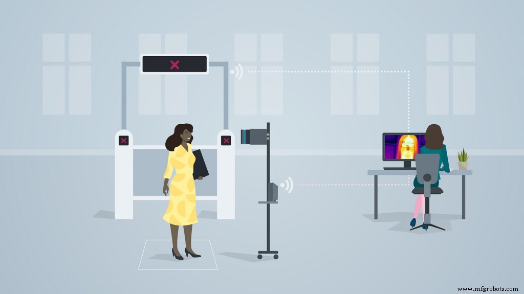
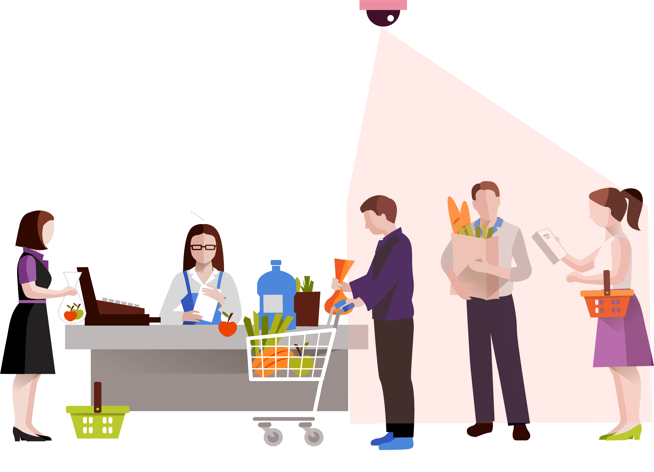
The retail market has been hit with a great impact due to the pandemic. After the malls and supermarkets have re-begun, it is necessary to ensure safety of all the customers who have entered the premises. For this purpose, manual temperature checking techniques have been set up. This increases the labour and also a risk of contact between the person checking the temperature and the person whose temperature is being check. This is demonstrated as follows:
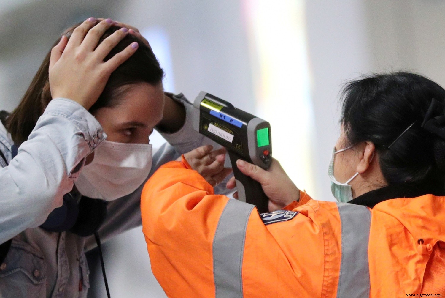
This image shows the close contact or less social distance maintained between the two persons.
There is a second flaw which is faced in manual temperature checking system:
For the temperatures which have been checked, the data of these recordings is not stored or not synchronised with an external device for monitoring the temperatures measured.
Taking in all these cons into consideration, I've come up with an Arduino based IoT solution deployed on the Arduino MKR WiFi 1010. The temperatures are measured using the Adafruit AMG8833 temperature module. Whenever a person is detected on the gate, the ultrasonic sensors, send the information to the Arduino MKR WiFi 1010 to give a command to the AMG 8833 module to take in temperature data. The module captures the data accurately and the data is projected on an IoT dashboard in real time. If an abnormal temperature reading of a person is detected, an alarm is set on so that the mall security and staff can immediately investigate upon the matter. The data collected is each given a timestamp and can be viewed on the ThingSpeak dashboard the temperature recording vs Time graph for each data.
Similarly, it can be also traced on which days and which time range, does the supermarket or the mall show abnormal temperature readings and more security measures can be implemented accordingly.
The below image shows wherethe setup can be embedded(The area where the setup can be installed)
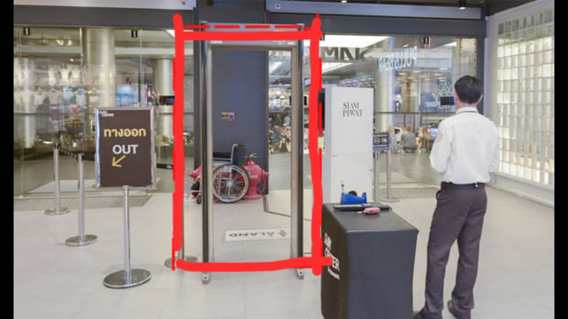
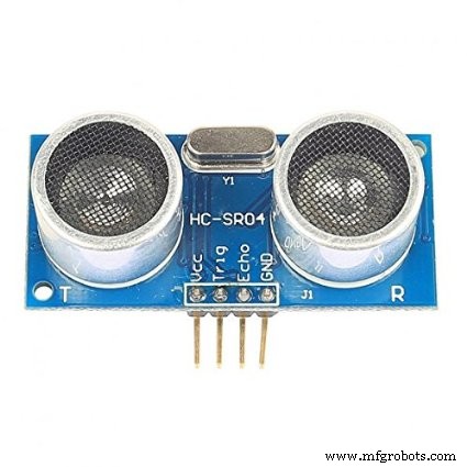
On the entry checking gate, HC-SR04 Ultrasonic Sensors can be installed which detects the entry of a person and sends the command to the Arduino MKR WiFi 1010 if the person is detected in a 20cm range. The Arduino microcontroller passes on the same command to the AMG 8833 temperature module to read the temperature of the person. This complete process takes time from the Ultrasonic Sensor detecting the person, to sending the command to the temperature module to detect the temperature. Hence, in order to sync with the delay, the temperature module is attached a bit far way from the Ultrasonic sensor.
Whenever a person walks in, the gate is opened ( Here, in the prototype, we are using the servo to function as a gate, but in further implementation of the project, the servo will be replaced by a heavy duty gate motor and controlled via motor driver, wherein the Arduino will be sending commands ). The temperature reading of the person is taken and this reading is sent to the thingspeak IoT dashboard in real time via the Arduino WiFi 1010. For this, an active wifi connection is required in the mall premises which is usually available in most of the cases. According to Research, the body temperature of a person with fever is approximately 38.1C which is 104F. Hence, if the Temperature module detects a temperature above this threshold, the servo turns 180Degrees and the Buzzer goes on to alarm people about the Person. Similarly, security and other mall staff can reach the area in time to control the situation when such a case happens.
The Logic works in the Following way:
├── PersonTemperature Detection MKR WiFi 1010
├── HC-Sr04 Ultrasonic sensor
│ ├── Person Detection
│ │ ├── If( Person distance =20) ,send command
├── Arduino
│ ├── if Ultrasonic sensor Sends a command;
│ │ ├── Open the gate - Servo(0)
│ │ ├── Activate the AMG8833 to take readings
│ │ ├── Send the Readings to ThingSpeak Dashboard
│ │ | ├── If Temperature> 38.1C
│ │ │ | ├── Close the gate - servo(180)
│ │ │ │ ├── Activate the Buzzer
│ │ └── ...Repeat the loop
In this way, the complete Logic of the Temperature Monitor Functions.
The circuit Diagram for the Temperature Model is given as follows:
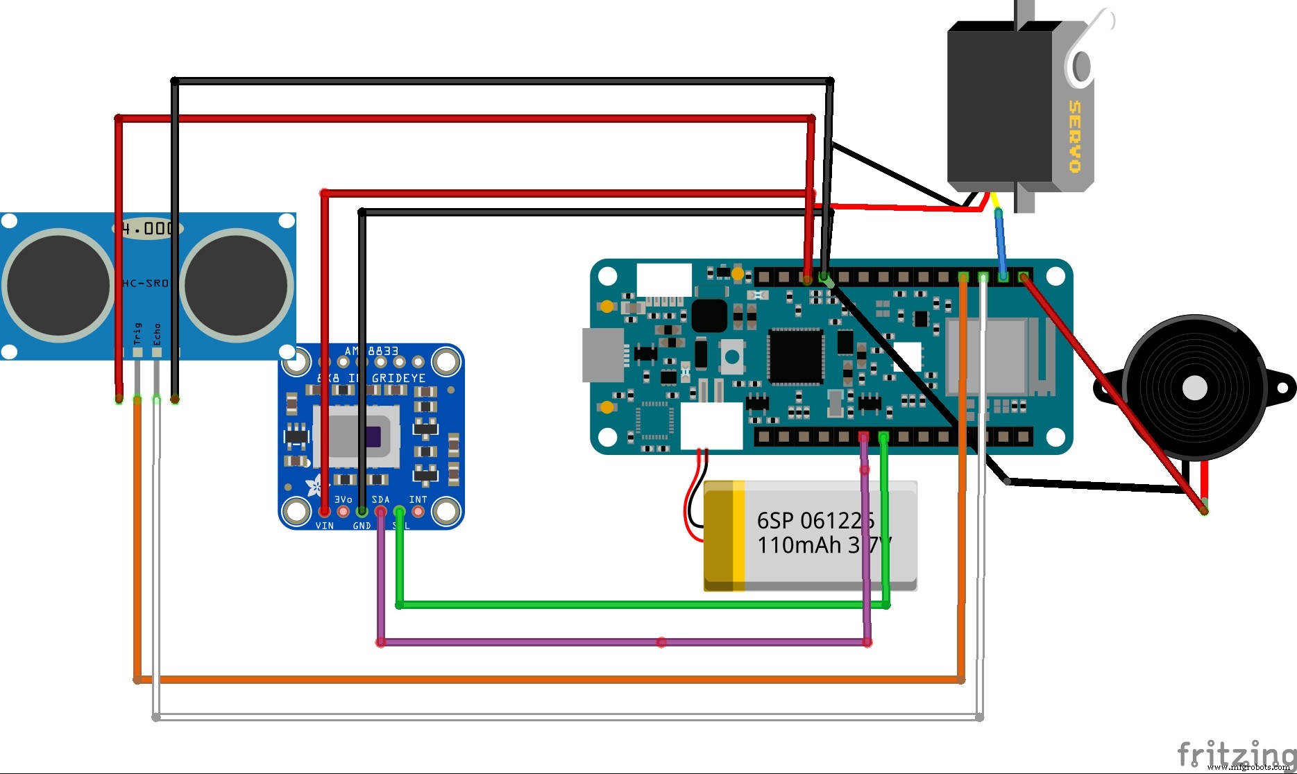
This is the complete Firmware and setup used in the project
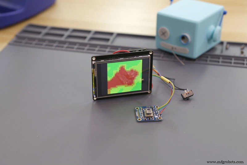
This simulation shows the data type captured by the AMG 8833 Thermal Cam and this data is sent to the Arduino MKR WiFi 1010 to transfer commands
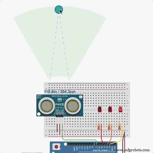
This simulation shows the distance captured by ultrasonic Sensor and this command is sent to the Arduino MKR WiFi to activate the AMG 8833 thermal sensor
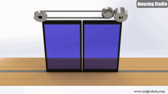
Instead of a servo based door opening system, I will be implementing a command system using motor driver to automate door sliding opening system as follows:
Setting up the IoT Dashboard:
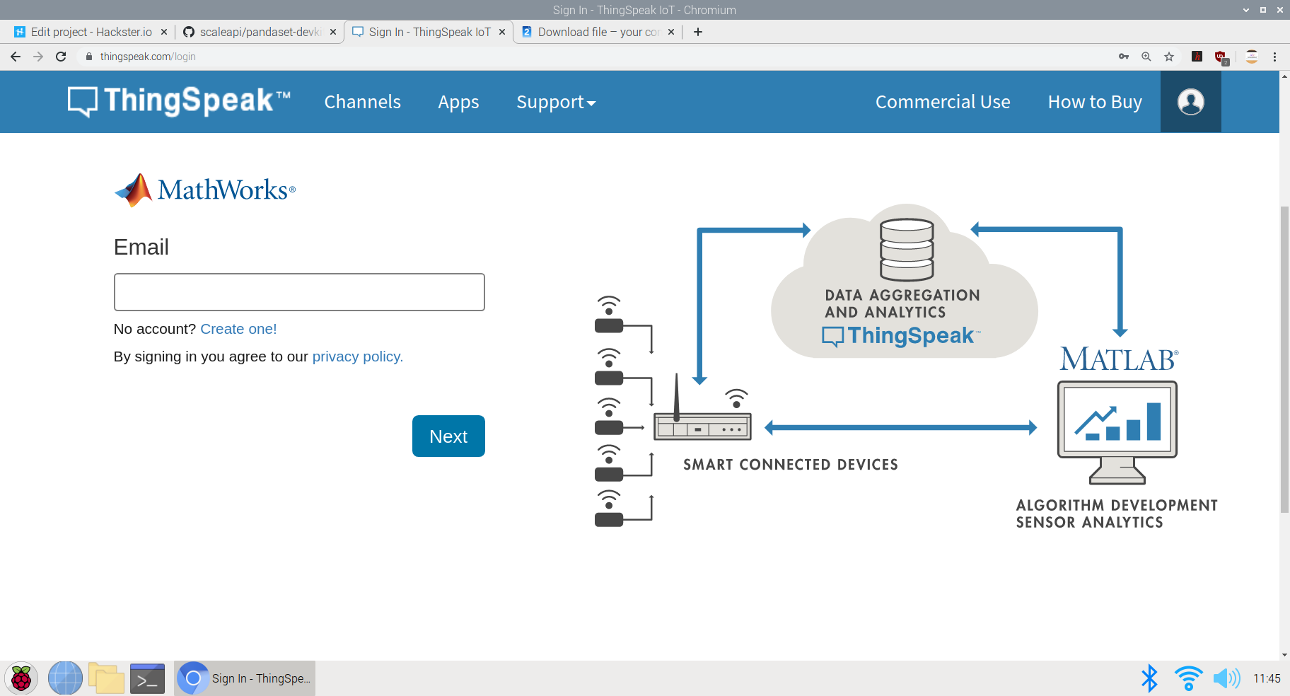
Using Thingsepak IoT Dashboard Setup:
ThingSpeak™ is an IoT analytics service that allows you to aggregate, visualize, and analyze live data streams in the cloud. ThingSpeak provides instant visualizations of data posted by your devices to ThingSpeak. With the ability to execute MATLAB® code in ThingSpeak, you can perform online analysis and process data as it comes in. ThingSpeak is often used for prototyping and proof-of-concept IoT systems that require analytics.
Since, ThingSpeak was easy to setup and use, I preffered to go with that dashboard. This interface allows the user to share the dashboard the security or staff department in the mall so that they can continuously monitor the people visiting the mall, and similarly impose restrictions at certain times when they feel the temperature risk is higher.
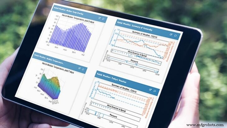
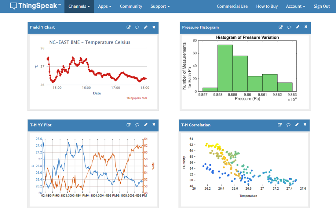
The above image represents the versatility of the thingspeak dashboard and the creative visualisations potrayed.
Logic used in the ThingSpeak IoT data collection process
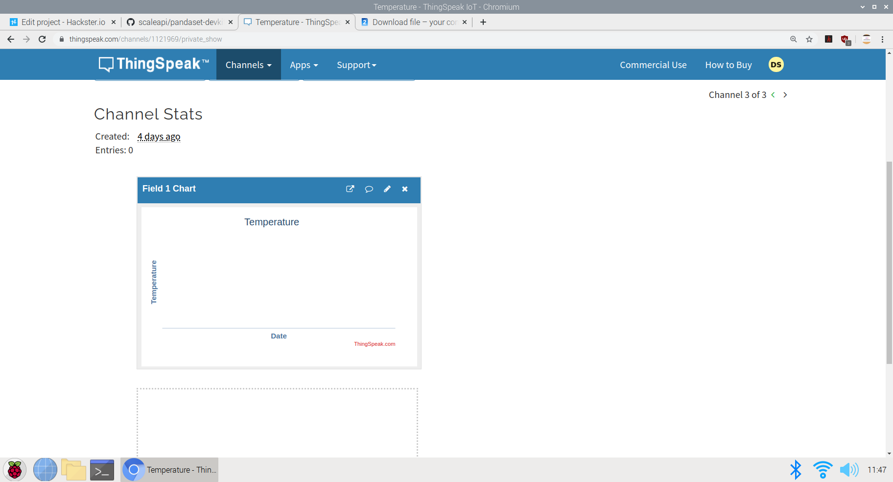
This image shows the creation of visualisations in different channels. Here, I've created a Temperature vs Time Graph in the visualisation section. The data collected by the AMG8833 sensor will be each allocated a timestamp and will be plotted on the graph to see the time for which each data is captured.
The data collected can be viewed in real time on the Public Dashboard here; ThingSpeak Temperature Dashboard
Similarly, this plot can be integrated cumulatively to a single Dashboard made open to the visitors of the mall to view the temperature data before entering the mall. If the visitors find an abnormal temperature reading at a particular day, they can prefer not to go to the supermarket or mall at that day to be safe,
The visualisation Integration data chart:
This chart can be embedded at a single dashboard with the readings of the charts of other malls and supermarkets in the particular area and hence, a unique visitor can check which mall is performing better than other mall in terms of safety and can prefer going to the mall where safety guidelines are followed and the people entering are not diagnosed with fever. This can help the Government help establish safety and trust within the people along with the re-opening of malls and retail sectors
The code of the following project can be either viewed in Github or in the Arduino Web editor here; Temperature-Model-code
The logic in the code goes as follows:
#include
#include
#include
#include ESP32_Servo.h
#include
#include
Servo servo1;
int trigPin =9;
int echoPin =8;
long distance;
long duration;
WiFiMulti WiFiMulti;
const char* ssid ="JioFiber-tcz5n"; // Your SSID (Name of your WiFi) - This is a dummy name, enter your wifi ssid here
const char* password ="**********"; //I have not mentioned the password here, while running the cript, you may mention your pwd
const char* host ="api.thingspeak.com/1121969";
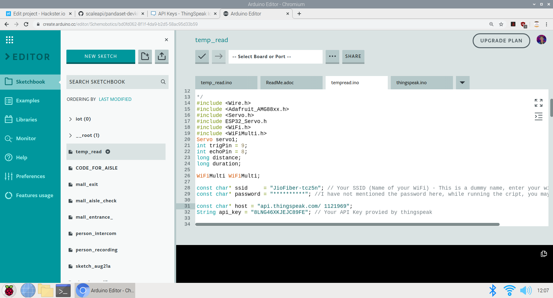
String api_key ="8LNG46XKJEJC89FE"; // Your API Key provied by thingspeak
Adafruit_AMG88xx amg; Here, I have defined some of the Libraries and Firmware along with the required setup for the WiFi host and the API-Key for the temperature dashboard on thingspeak
Here's an image of the Code in progress:
The next part of the code is Setting up the required components before the actual loop begins:
These are the prerequisites before looping the actual code. I have defined the Servo pin and the Ultrasonic sensors while also begun the testing of the AMG 8833 to see if it can read data or if its connected
void setup()
{
 Serial.begin(9600);
servo1.attach(7);
 pinMode(trigPin, OUTPUT);
 pinMode(echoPin, INPUT);// put your setup code here, to run once:
}


{
 Connect_to_Wifi();
 Serial.println(F("AMG88xx test"));

 bool status;

 // default settings
 status =amg.begin();
 if (!status) {
 Serial.println("Could not find a valid AMG88xx sensor, check wiring!");
 while (1);
 }

 Serial.println("-- Thermistor Test --");

 Serial.println();

 delay(100); // let sensor boot up
}
The next part is the Void Loop where the complete function is carried out. Here, Initially I have set the gate to open to allow the entry of each person. The AMG 8833 performs data collection and reads the temperature of the people coming inside. If the temperature is higher than the expected threshold, the gate is closed and an alarm(buzzer) is set on to alert people and not allow the entry of the person
void loop()
ultra();
 servo1.write(0);
 if(distance <=20){
 Serial.print("Thermistor Temperature =");
 Serial.print(amg.readThermistor());
 Serial.println(" *C");

 Serial.println();
 // call function to send data to Thingspeak
 Send_Data();
 //delay
 delay(50);

 if(amg.readThermistor()> 38.1) // if a person with fever is detetcted, he is not allowed to enter
 // a person with fever has an avg body temperature of 38.1degree celsius
 servo1.write(180);
 digitalWrite(6, HIGH); //Turns on the buzzer to alarm people
 }
The last part is sending the data to the ThingSpeak Dashboard:
Here, since I have only one field in the channel, all the data will be sent to that field. The captured, amg.readThermistor() data is sent to the dashboard.
void Send_Data()
{

 Serial.println("Prepare to send data");

 // Use WiFiClient class to create TCP connections
 WiFiClient client;

 const int httpPort =80;

 if (!client.connect(host, httpPort)) {
 Serial.println("connection failed");
 return;
 }
 else
 {
 String data_to_send =api_key;
 data_to_send +="&field1=";
 data_to_send +=string(amg.readThermistor());
 data_to_send +="\r\n\";

 client.print("POST /update HTTP/1.1\n");
 client.print("Host:api.thingspeak.com\n");
 client.print("Connection:close\n");
 client.print("X-THINGSPEAKAPIKEY:" + api_key + "\n");
 client.print("Content-Type:application/x-www-form-urlencoded\n");
 client.print("Content-Length:");
 client.print(data_to_send.length());
 client.print("\n\n");
 client.print(data_to_send);

 delay(200); // reduced delay to perform real time data collection
 }

 client.stop();

} 
This ends the code section of the project and we move on to explanation of the use and GO TO MARKET part of the project
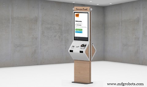
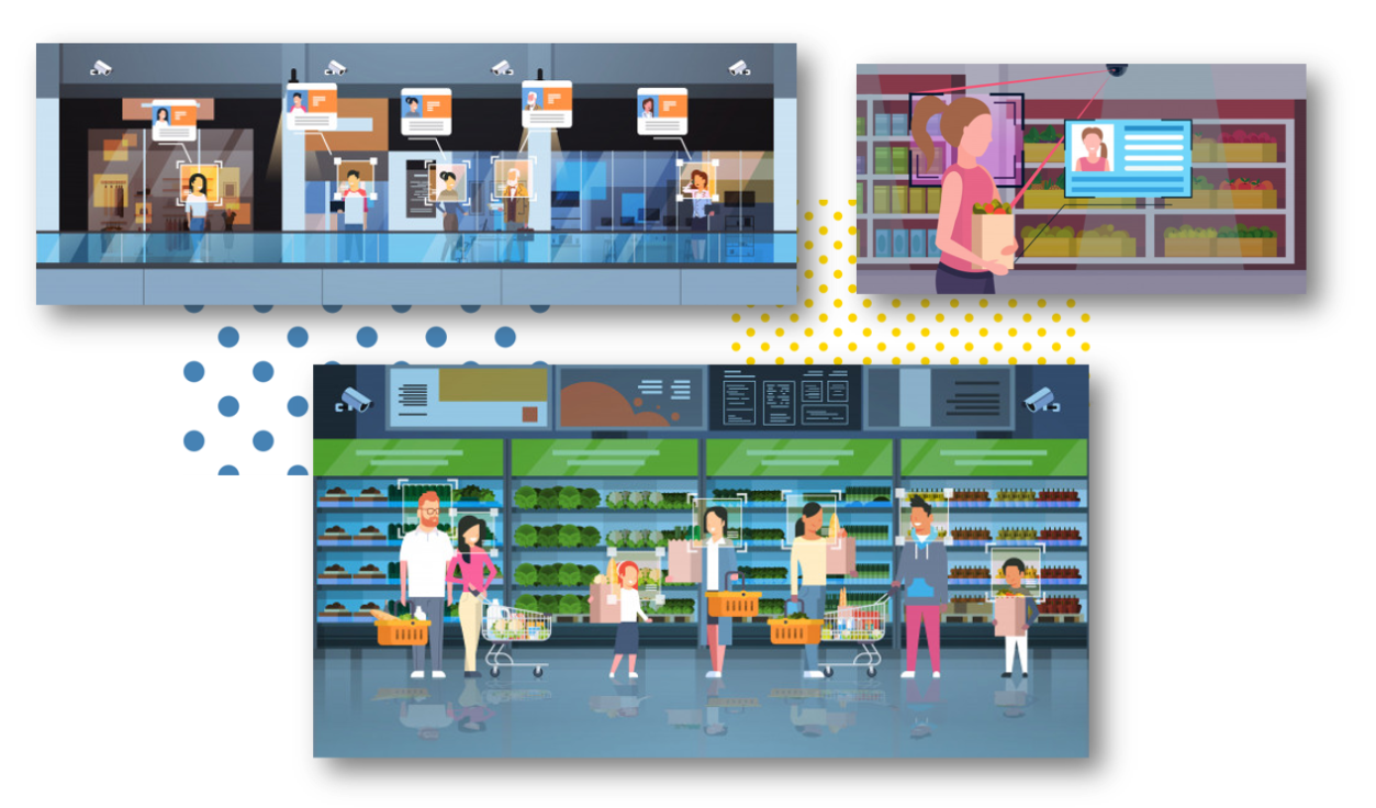
The above image shows the implementation of the methodology and model in supermarkets and malls.
GO TO MARKET &PRACTICALITY:
- Malls and Supermarkets can use this to identify Abnormal Temperature data and this data can be observed even for a certain day at a certain point of time.
- Implement Strategies using this data to ensure Safety and Compliance.
- Decrease Labour and automate Temperature Monitoring Process
- Offer Dashboard to the visitors to monitor if the mall is safe and and accordingly visit the mall at the safest point of time.
- This product can be used to ensure the visitors that the mall is a safe place and hence, can increase the sales and visits following Government guidelines
- Companies offering IoT based solutions can invest in this product for mass production and distribution.
- The more the supermarkets using this product, the more the access to data to the government and more the choice to customers to select the preferable safest place in their locality.
- Comparatively affordable solution as compared to manual temperature monitoring as it decreases the labour cost + decreases the rate of infection when compared to manual monitoring where the person taking temperature has to be close to the visitor to capture the temperature.
4th Project:TinyML &IoT based queue monitoring and establishing system deployed on the Arduino 33 BLE Sense:
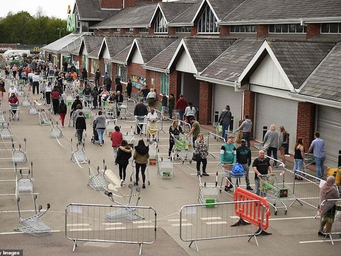
Just as the mall and the retail sector has opened, queue management in malls and supermarkets has become a big problem. Due to the pandemic, restricting only a certain amount of people to go inside the mall has has to be followed by the malls to ensure safety compliance. But this is done manually which increases labour work. Also the data for the number of people inside the mall at a given point of time is not available to the visitors of the mall. If this data would have been made available to the the visitors of the mall, it would increase the percentage of people visiting the mall.
Trying to run a shop or a service during the ongoing Corona crisis is certainly a challenge. Serving customers while keeping them and employees safe is tricky, but digital queuing can help a lot in this regard. The technologies behind virtual queues are not entirely new; the call for social distancing just highlights some of the many benefits they offer.
Most countries have introduced legal measures to combat the spread of COVID-19. To ensure customer satisfaction whilst adhering to the new regulations, one thing is for sure:long queues and crowded lobbies need to go. Digital queuing (also referred to as virtual or remote queuing) technology allows businesses to serve their customers in a timely manner while they stay out of harm’s way.
Generally speaking, you will likely find one or more of the following types of queue management solutions in a given retail environment:
- Structured queues: Lines form in a fixed, predetermined position. Examples are supermarket checkouts or airport security queues.
- Unstructured queues: Lines form naturally and spontaneously in varying locations and directions. Examples include taxi queues and waiting for consultants in specialist retail stores.
- Kiosk-based queues: Arriving customers enter basic information into a kiosk, allowing staff to respond accordingly. Kiosks are often used in banks, as well as medical and governmental facilities.
- Mobile queues: Rather than queuing up physically, customers use their smartphones. They do not have to wait in the store but rather can monitor the IoT Dashboard to see wait time at the store.
Long queues, whether they are structured or unstructured, often deter walk-in customers from entering the store. Additionally, they limit productivity and cause excess stress levels for customers and staff.
Does effective queue management directly affect the customer experience?
There is an interesting aspect about the experience of waiting in line:The waiting times we perceive often do not correspond with the actual times we spent in line. We may attribute a period of time falsely to be “longer” than normal or deem another period “shorter” despite it actually exceeding the average waiting time. For the most part, this has to do with how we can bridge the time waiting.
“Occupied time (walking to baggage claim) feels shorter than unoccupied time (standing at the carousel). Research on queuing has shown that, on average, people overestimate how long they’ve waited in a line by about 36 percent.”
The main reason that a customer is afraid to visit any supermarket is the problem of insufficient data. Visitors do not know the density of people inside the mall. The higher the number of people inside the mall, the higher is the risk of visiting the mall. Manually calculating the number of people who go enter and exit the mall and updating this data in real time is not possible. Also, a vistor does not know which day and at which time is is best suited to visit the mall. The visitor also does not know the wait time of each mall so that he can go with other supermarkets nearby if the wait time over there is less. As a result, all this leads to less conversion of people and accordingly less number of people visiting the mall. If the visitors have the access to population data, they have a sense of trust and leads to increase in sales of malls. Hence, I've come up with an Arduino Based TinyML and IoT solution to make this data available to the visitors and also increase the conversion of visitors in the mall by following the necessary safety guidelines. If the visitors have the access to population data, they have a sense of trust and leads to increase in sales of malls. Hence, I've come up with an Arduino Based TinyML and IoT solution to make this data available to the visitors and also increase the conversion of visitors in the mall by following the necess
This solution is based on computer vision and person detetction algorithm based on tensorflow framework.
It functions in the following way :
This solution is implemented on the gates of the mall or the supermarket. The Arducam mini 2mp keeps capturing image data and sends it to the Arduino 33 BLE Sense to process and classify this data. If a person is detected, The arduino increases the count of the stored data of number of people inside the mall by 1. Since a person is detected, the Servo motor rotates, opening the entrance to allow the person inside. For each person allowed inside, the data is sent to the ThingSpeak IoT dashboard which is open for the vistors to view.
When the person count increases the 50 threshold limit(This threshold can be altered depending upon the the supermarket size), the gate is closed and a wait time of 15min is set until the customers inside exit the store. The wait time is then displayed on the LED matrix display screen so that the customers in the queue can know the duration they have to wait for.
The people can also keep a track of the number of people inside the store. The number of people allowed to enter inside the store at a single time is 50 people.
The physical queuing unit of this product, helps in establishing queues while the IoT Dashboard helps in projecting the total count of the customers going in the store and total count of the customers going out of the store. Currently this is the dashboard data that will be displayed but I am working on a logic for displaying the waiting time required for the customer to get inside the mall. The logic for it is pretty simple, it depends on the number of people inside the mall. The total no of people entering the mall displayed on dashboard minus the total no of people exited the mall displayed on the dashboard. This will give us an outcome of the total no of people inside the store. The next operation would be the total no of people outside the store subtracted by the threshold (limit that the store can accommodate). If the outcome is a negative integer, the waiting time would be multiplication of the negative integer by the negative of the average time a person spends inside the store. If the outcome of the operation would be a positive integer, the wait time would be none.
Heading towards the implementation of the physical queuing system:
The following Softwares have been used in designing this model:
- TensorFlow lite
- ThingSpeak
- Arduino Web Editor
In this person detection model, I have used the Pre-trained TensorFlow Person detection model apt for the project. This pre-trained model consists of three classes out of which the third class is with undefined set of data:
"unused",
"person",
"notperson"
In our model we have the Arducam Mini 2mp plus to carry out image intake and this image data with a decent rate of fps is sent to the Arduino Nano 33 BLE Sense for processing and and classification. Since the Microcontroller is capable of providing 256kb RAM, we change the image size of each image to a standard 96*96 for processing and classification. The Arduino Tensorflow Lite network consists of a deep learning framework as:
- Depthwise Conv_2D
- Conv_2D
- AVERAGE Pool_2D
- Flatten layer
This deep learning framework is used to train the Person detection model.
The following is the most important function defined while processing outputs on the Microcontroller via Arduino_detetction_responder.cpp
// Process the inference results.
 uint8_t person_score =output->data.uint8[kPersonIndex];
 uint8_t no_person_score =output->data.uint8[kNotAPersonIndex];
 RespondToDetection(error_reporter, person_score, no_person_score);
In the following function defining, the person_score , the no_person_score have been defined on the rate of classification of the data.
using these defined functions, I will be using it to give certain outputs on the basis of confidence of the person-score and the no_person_score .
The detection responder logic of the code works in the following way:
├── Person Detection and responder - Entry
├── Arducam mini 2MP Plus
│ ├──Image and Video Data to Arduino
├── Arduino BLE 33 Sense
│ ├── processing and classification of the input data
│ │ ├── If person detected, open the gate - servo(180)
│ │ ├── If no person detected, close the gate - servo(0)
│ │ ├── Send the number of people entered count to to ThingSpeak Dashboard via ESP8266 -01
│ │ | ├── If people count has exceeded 50
│ │ │ | ├── Close the gate &wait for 15min to let the people inside move out
│ │ │ │ ├── Display wait time on a LED Matrix
│ │ └── ...Repeat the loop
├── Person Detection and responder - Exit
├── Arducam mini 2MP Plus
│ ├──Image and Video Data to Arduino
├── Arduino BLE 33 Sense
│ ├── processing and classification of the input data
│ │ ├── If person detected, open the gate - servo(180)
│ │ ├── If no person detected, close the gate - servo(0)
│ │ ├── Send the number of people entered count to to ThingSpeak Dashboard via ESP8266 -01
│ │ └── ...Repeat the loop
Adhering to the logic used in the model, the Arducam mini 2mp plus will continuously capture Image data and sends this data to the Arduino 33 BLE Sense to process and classify the data. The overall model size is 125KB. If a person has been detected, the Arduino sends the command to the servo to rotate to servo to 180degree. If a person is not detected, the servo is rotated to 0degree and the gate is closed. Each time a person is detected, the the count increments by 1. If the count exceeds the 50 threshold, no more person is allowed inside and a wait time of 15min is set.
The wait time is continuously displayed and updated on the LED Matrix dislplay.
This count is also displayed on the ThingSpeak IoT dashboard via the ESP8266 01
Through the Dashboard, an individual can easily view the number of people are inside at a given day at a given point of time.
At the exit gate, the same logic is set. If a person is detected, the gate is opened while if no person is detected, the gate is closed. Each time a person is detected, the count increases by 1. This count is displayed on the ThingSpeak IoT dashboard.
In this way one can monitor the number of people entering and the number of people exiting.
Since the two models for entry and exit are deployed on two different microcontrollers, calculating the average wait time based on data from different microcontroller is a bit hard, but this uses a simple logic function.
x =No of people who have entered
Y =No of people who have exited
X - Y =No of people who are inside the mall
Z =Threshold of the no of people who are allowed to be inside the mall
let Z-(X-Y) =count {this is the number of people (in negative) who have either crossed the threshold limit or are below the threshold limit
If "count" is negative, The wait time is equal to count*(the negative of the average time a person spends inside the mall)
if "count" is positive, the wait time is zero
In this way, the average queue time calculating algorithm is imposed.
Working of the Firmware:

This is the complete setup of the firmware designed on Fritzing.
This model comprises of the following firmware used:
- Arduino 33 BLE sense - Used to process the data gathered, classifies the data processes, sends the command according to the logic fed.
- MG959 / MG995 Servo - Heavy duty servo( An external power supply may be applied) - To open and close the gates as per microcontroller command.
- Arducam Mini 2mp plus - Continuous Raw data image accumulation from source.
- Adafruit lithium ion charger - Used to deliver charge through the lithium battery
- Lithium ion Battery - power source
- ESP8266 - 01 - Used for sending data to the ThingSpeak dashboard via WiFi network.
- MAX7219 4 in 1 display - Used for displaying the wait time on the display screen.
Functioning and Working of Logic in Code:
The following are the Libraries included in themain.ino code for functioning of the model.
#include

#include "main_functions.h"

#include "detection_responder.h"
#include "image_provider.h"
#include "model_settings.h"
#include "person_detect_model_data.h"
#include "tensorflow/lite/micro/kernels/micro_ops.h"
#include "tensorflow/lite/micro/micro_error_reporter.h"
#include "tensorflow/lite/micro/micro_interpreter.h"
#include "tensorflow/lite/micro/micro_mutable_op_resolver.h"
#include "tensorflow/lite/schema/schema_generated.h"
#include "tensorflow/lite/version.h"
In the following code snippet, the loop is defined and performed. Since this is the main.ino code, it controls the core functioning of the model - used to run the libraries in the model.
void loop() {
 // Get image from provider.
 if (kTfLiteOk !=GetImage(error_reporter, kNumCols, kNumRows, kNumChannels,
 input->data.uint8)) {
 TF_LITE_REPORT_ERROR(error_reporter, "Image capture failed.");
 }

 // Run the model on this input and make sure it succeeds.
 if (kTfLiteOk !=interpreter->Invoke()) {
 TF_LITE_REPORT_ERROR(error_reporter, "Invoke failed.");
 }

 TfLiteTensor* output =interpreter->output(0);

 // Process the inference results.
 uint8_t person_score =output->data.uint8[kPersonIndex];
 uint8_t no_person_score =output->data.uint8[kNotAPersonIndex];
 RespondToDetection(error_reporter, person_score, no_person_score);
}
In the following code snippet, the necessary libraries required to inference the image to be captured is displayed. The images after captured are converted to a 96*96 standardised size which can be interpreted on the arduino board.
Here, the Arducam mini 2mp OV2640 library has been utilised.
This code has been provided in the arduino_image_provider.cpp snippet
#if defined(ARDUINO) &&!defined(ARDUINO_ARDUINO_NANO33BLE)
#define ARDUINO_EXCLUDE_CODE
#endif // defined(ARDUINO) &&!defined(ARDUINO_ARDUINO_NANO33BLE)

#ifndef ARDUINO_EXCLUDE_CODE

// Required by Arducam library
#include
#include
#include
// Arducam library
#include
// JPEGDecoder library
#include

// Checks that the Arducam library has been correctly configured
#if !(defined OV2640_MINI_2MP_PLUS)
#error Please select the hardware platform and camera module in the Arduino/libraries/ArduCAM/memorysaver.h
#endif

// The size of our temporary buffer for holding
// JPEG data received from the Arducam module
#define MAX_JPEG_BYTES 4096
// The pin connected to the Arducam Chip Select
#define CS 7

// Camera library instance
ArduCAM myCAM(OV2640, CS);
// Temporary buffer for holding JPEG data from camera
uint8_t jpeg_buffer[MAX_JPEG_BYTES] ={0};
// Length of the JPEG data currently in the buffer
uint32_t jpeg_length =0;

// Get the camera module ready
TfLiteStatus InitCamera(tflite::ErrorReporter* error_reporter) {
 TF_LITE_REPORT_ERROR(error_reporter, "Attempting to start Arducam");
 // Enable the Wire library
 Wire.begin();
 // Configure the CS pin
 pinMode(CS, OUTPUT);
 digitalWrite(CS, HIGH);
 // initialize SPI
 SPI.begin();
 // Reset the CPLD
 myCAM.write_reg(0x07, 0x80);
 delay(100);
 myCAM.write_reg(0x07, 0x00);
 delay(100);
 // Test whether we can communicate with Arducam via SPI
 myCAM.write_reg(ARDUCHIP_TEST1, 0x55);
 uint8_t test;
 test =myCAM.read_reg(ARDUCHIP_TEST1);
 if (test !=0x55) {
 TF_LITE_REPORT_ERROR(error_reporter, "Can't communicate with Arducam");
 delay(1000);
 return kTfLiteError;
 }
The final part where in the complete model is controlled is the Arduino_detection_responder.cpp.
This is a small code snippet of the entire logic used. When the confidence score of a person is greater than the confidence score of no person, the gate is opened and it is assumed that the person is detected. For this purpose the servo is moved to 0Degree to open the gate. On the detection of a person, the count is incremented by 1 =initially which began at 0. This count indicates the number of people coming inside. The num value of the count is sent to the ThingSpeak IoT dashboard which represents the number of people entering. When the count reaches the value of 50; the gate is closed and a wait time of 15min is imposed on the queue. The gate is closed and wait time is imposed each time 50 people enter. For this a logic of multiples of 50 is set
// Switch on the green LED when a person is detected,
 // the red when no person is detected
 if (person_score> no_person_score) {
 digitalWrite(LEDG, LOW);
 digitalWrite(LEDR, HIGH);
 servo_8.write(0); // this servo moves to 0degrees in order to open the mall door when a person is detected to ensure no touch entry system
 count++

 } else {
 digitalWrite(LEDG, HIGH);
 digitalWrite(LEDR, LOW);
 servo_8.write(180); // this servo moves to 180degrees when no person is detected
 }

 TF_LITE_REPORT_ERROR(error_reporter, "Person score:%d No person score:%d",
 person_score, no_person_score);
}


// Now we have let in 50people inside the store, so we set a delay of 15min wait time for others waiting outside to let them in
// Displaying wait time on the screen every 1min

 if(count =y*50) // when people are detected in multiples of 50, we instruct it to start displaying wait time to other people to wait until 15 min
 myDisplay.setTextAlignment(PA_CENTER);
 myDisplay.print("Waiting 15min");
delay(60000); 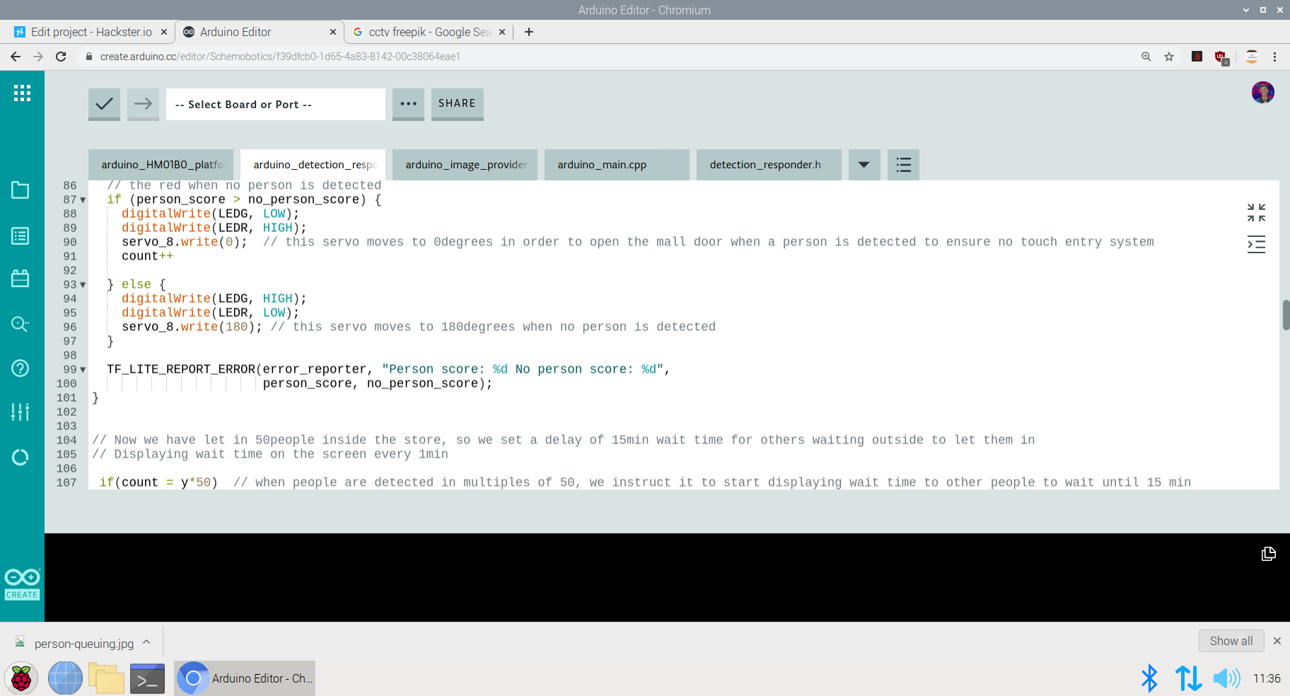
Setting up the ThingSpeak Dashboard:
Since the features in Thingspeak Dashboard are limited, I will not be implementing the Time prediction algorithm right now but I am working on the logic to communicate and write data from the Dashboard to microcontroller to perform the time calculation algorithm.
In the ThingSpeak Dashboard, I have added two fields; one for entry and the other one for exit.
The co-ordinates for the store or mall for which the queuing system is displayed, is also added in the form of a map.
The data displayed for the first field is gathered through the entry responding logic and the data displayed for the second field is gathered through the exit responding logic.
This is the snip of the two different logics used in the model.
The ThingSpeak Dashboard can be made available to the the staff of the store to check the number of people entering the store in real time and the number of people exiting the store in real time. This data can also be observed to see the analysis of the data at a given day at a a given time to check and impose further restrictions if required if the limit of people in the store exceeds the expected number of people at a given day
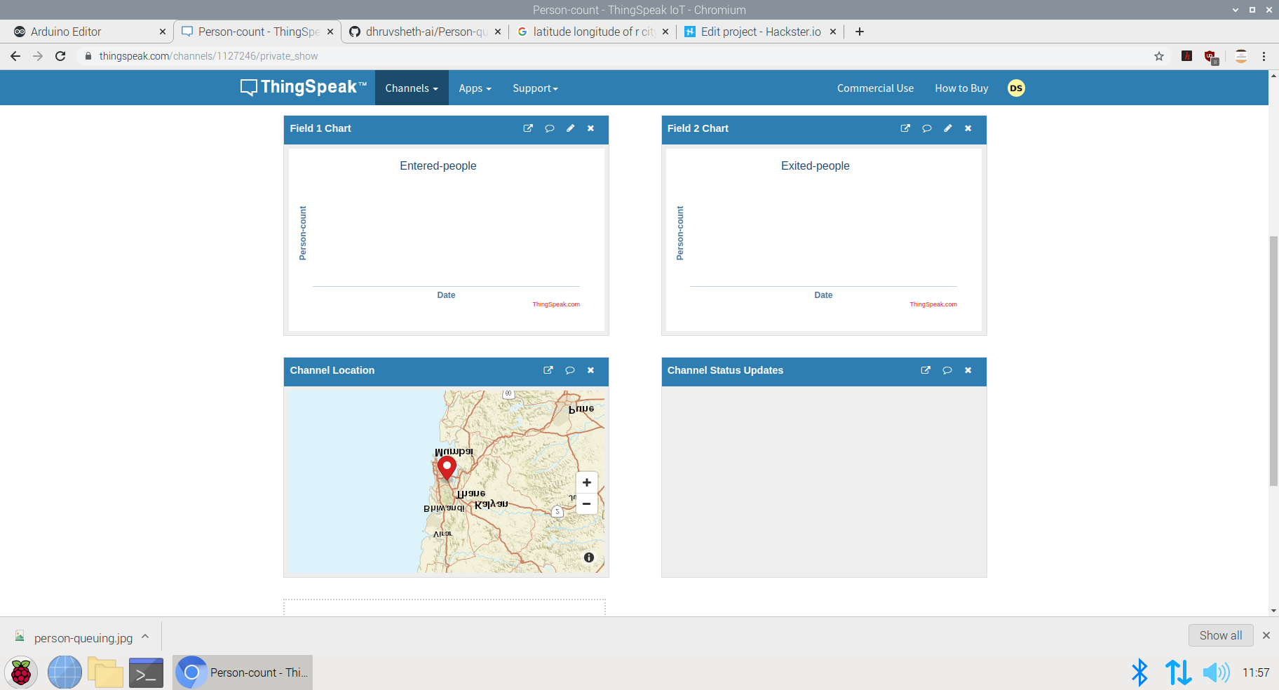
This Dashboard can be viewed here:IoT Dashboard
The following represents the field created for this purpose.
Now, a question might arise that for person detection model that this model can be replaced by ultrasonic or infrared sensors. Flaws in Ultrasonic Sensors or Infrared Based Sensors:These sensors are not exactly accurate and for the real time person count display, these sensors may provide wrong readings. Also, these sensors add as additional hardwares while in Go to Market Solutions, the person detection algorithm can be implemented in existing cameras and can reduce hardware cost. The data from these cameras could be sent to the Arduino BLE sense for central Classification and data processing.
GO TO MARKET &PRACTICALITY:
- Malls and Supermarkets can use this to identify The count of people entering and exiting the mall in real time.
- Implement Strategies using this data to ensure Safety and Compliance with efficient Queue management algorithms.
- Decrease Labour and automate Queue Management Process
- Offer Dashboard to the visitors to monitor the density of people inside the mall and accordingly visit the mall at the safest point of time.
- This product can be used to ensure the visitors that the mall is a safe place and hence, can increase the sales and visits following Government guidelines
- Companies offering Ai and IoT based solutions can invest for mass production and distribution.
- The more the supermarkets using this product, the more the access to data to the government and more the choice to customers to select the preferable safest place in their locality along with the the queue time required for each store can be monitored. This will lead to a wide range of options of supermarkets in the locality comparing the queue time and safety.
- Comparatively affordable solution as compared to manual queuing system and updating information manually to the Dashboard.
- Utilize real-time CCTV footage to impose Queue management in a mall/shop through person detection in terms of timely trends and spatial analysis of person density in the mall.
- Enable Stores to make better, data-driven decisions that ensure your safety and efficient Queues based on autonomous queuing system.
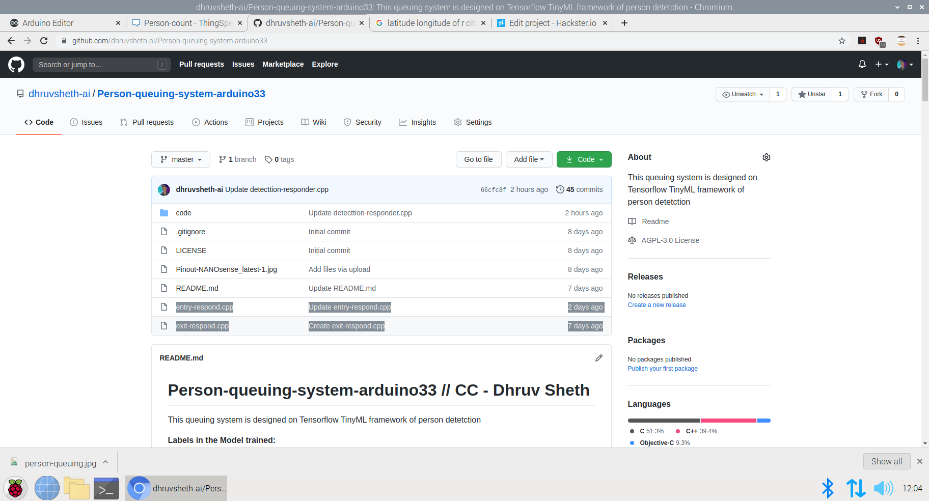
Github Code:Arduino Autonomous TinyML and IoT based queuing system.
Addition to the Existing Person Detection Algorithm- Mask Detection System:
Mask Detection Model based on TinyML :
Dr. Kierstin Kennedy, chief of hospital medicine at the University of Alabama at Birmingham, said, “Masks can protect against any infectious illness that may be spread by droplets. For example, the flu, pertussis (whooping cough), or pneumonia.”
Adding that wearing a cloth mask has benefits beyond slowing the spread of COVID-19, and that source control can reduce the transmission of many other easily spread respiratory infections — the kind that typically render people infectious even before they display symptoms, like influenza.
Until the threat of this pandemic has been neutralized, people should embrace the protection masks allow them to provide to those around them.
After all, it’s not necessarily about you — it’s about everyone you come in contact with.
It’s not at all uncommon to be an asymptomatic carrier of the new coronavirus — which means that even if you have no symptoms at all, you could potentially transmit the virus to someone who could then become gravely ill or even die.
Adhering to this, I decided to increase the necessity of wearing face-masks along with touch-free systems to increase safety in malls and supermarkets. Along with the person detection algorithm, I decided to make a custom face mask detection model which detects face masks and displays this data on the ThingSpeak IoT dashboard to increase awareness among mall staff as well as the visitors coming inside so that they are aware of the time trends when the most number of people are without masks. Through this there is a increases of sense of warning and awareness in people to wear masks. Accordingly, the store staff can keep a monitor on these trends and increase restrictions based on data driven statistics.
Deciding upon the Logic and Dataset of the Model:
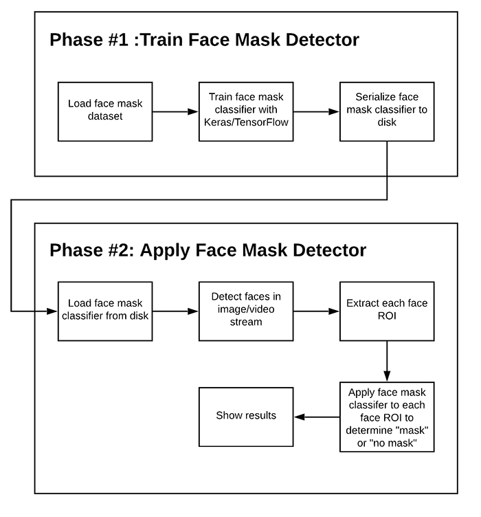
This is an overall Logic used in most of face mask detection algorithms. Since, we are deploying this model to an Arduino 33 BLE Sense, the deployment process of this model will vary.
There are two steps involved in constructing the model for Face Mask Detection.
- Training: Here we’ll focus on loading our face mask detection dataset from disk, training a model (using Keras/TensorFlow) on this dataset, and then serializing the face mask detector to disk
- Deployment: Once the face mask detector is trained, we can then move on to loading the mask detector, performing face detection, and then classifying each face as
maskorno_mask
Dataset used in training this model:
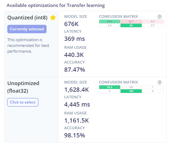
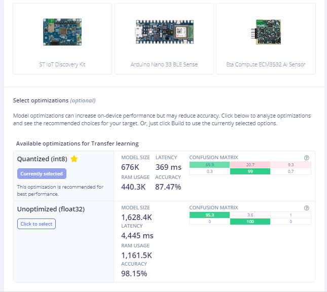
The dataset used in this process consists of 3500 images but to reduce the size of the model, and feed in accurate model images, I have used 813 images to increase accuracy of the model by decreasing bulk size. This model is an average 676K in size and utilizes nearly 440.3K Ram. Since this model is the optimized version of the original model, the accuracy of the model is 87.47% as compared to 98.15% in the non-optimized one.
The following Softwares have been used in designing this model:
- TensorFlow lite
- ThingSpeak
- Arduino Web Editor
Heading towards designing the model in EdgeImpulse Studio:
Powerful deep learning models (based on artificial neural networks) are now reaching microcontrollers. Over the past year great strides were made in making deep learning models smaller, faster and runnable on embedded hardware through projects like TensorFlow Lite for Microcontrollers, uTensor and Arm’s CMSIS-NN; but building a quality dataset, extracting the right features, training and deploying these models is can still be complicated.
Using Edge Impulse you can now quickly collect real-world sensor data, train ML models on this data in the cloud, and then deploy the model back to your Arduino device. From there you can integrate the model into your Arduino sketches with a single function call.
Step 1 - Acquisition of Data in the Edge Impulse Studio:
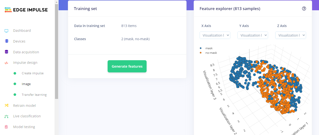
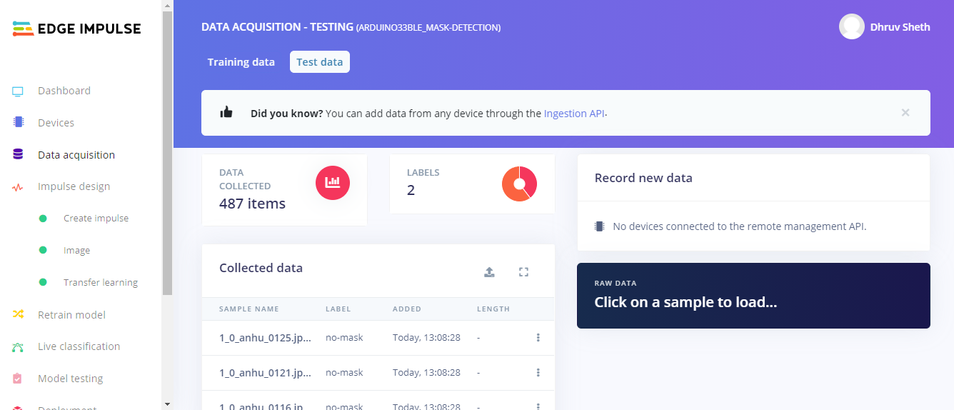
Using the dataset of 3500 images, I filtered these images to the best performing images and finally fed in 813 images totally in the Training Data and 487 images in the testing Data. I labelled these classes as mask and no_mask.
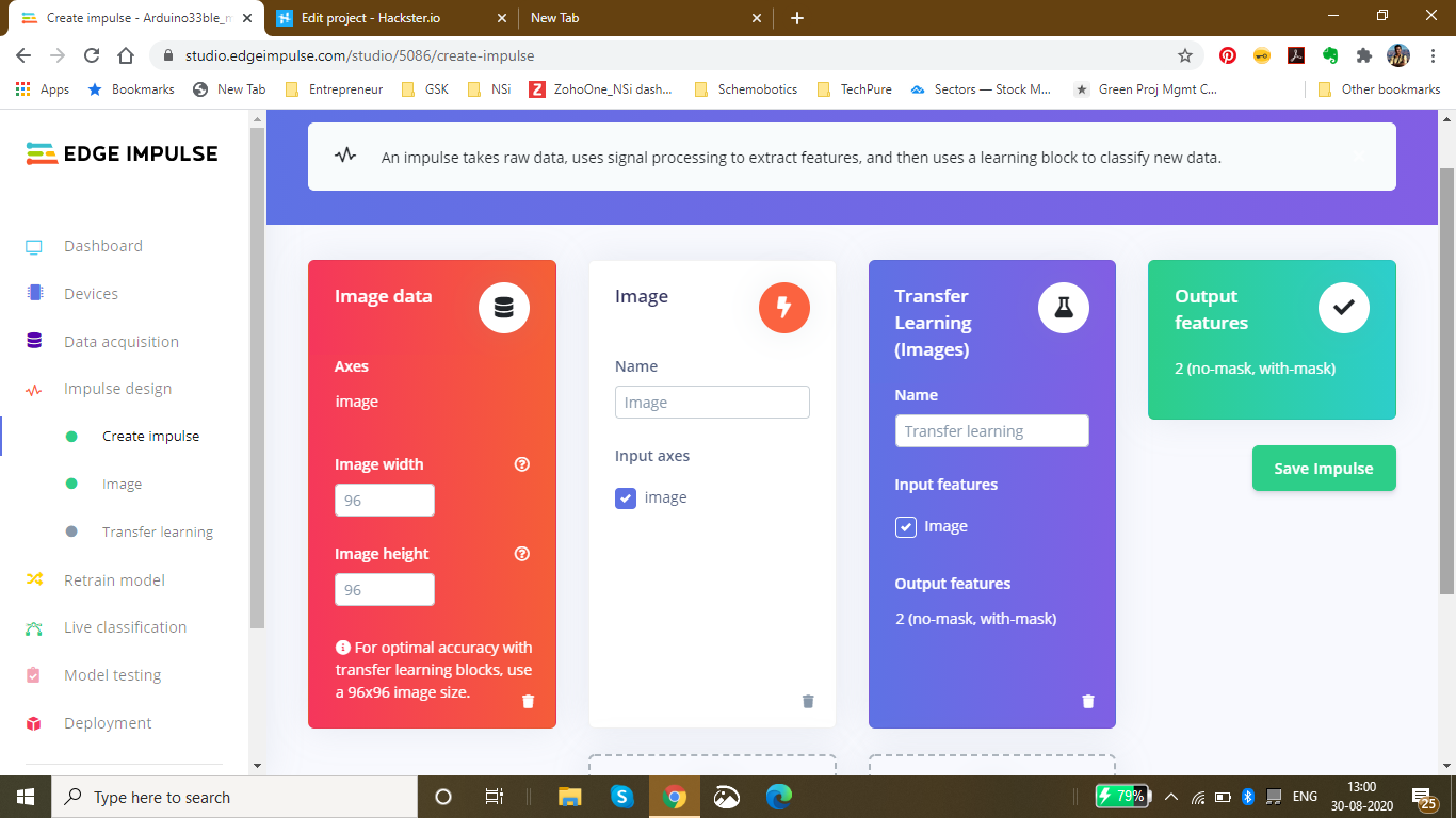
Then, I went ahead creating an impulse design which best suited the Model type. For optimal accuracy its recommended to use a standard image size which is 96*96 and also works the best on the Arduino 33 BLE Sense. Since the input type was images, I went ahead and selected "images" in the processing block. For the transfer learning block, the type recommended for image learning is Transfer Learning (Images) which is a Fine tune a pre-trained image model on your data. with Good performance even with relatively small image datasets.
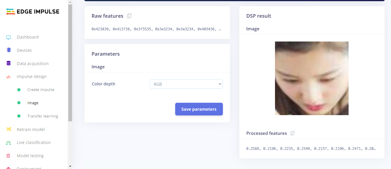
The next step was saving the parameters based on color depth. Here, I have selected RGB because in the dataset I am using for mask detection, color is also an important feature of classification instead of grayscale. In this page, we can also see the raw features with the processed features of the image
After Feature Generation I obtained the classification graph or the feature explorer where I could see the classes based on their classifications. The blue dots represent mask images and the orange dots represent the no_mask images.
In this feature generation, I obtained a fair classification with a distinct classification plot.
Finally, Moving on to the Transfer Learning Plot:
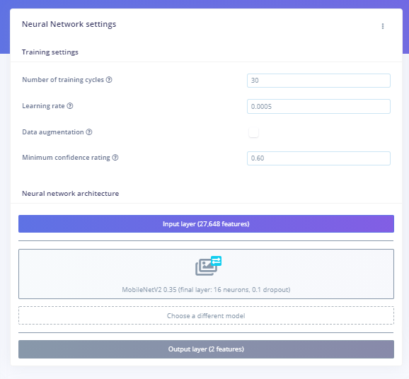
Here, I set the number of training cycles/epochs as 30 to get the highest accuracy with minimum val_loss. It so happens that if we train the model based on many training cycles, the accuracy graph starts to decrement after a certain number of epochs and the val_loss increases. Therefore I decided to limit the epochs to 30 which proved to be perfect. The learning rate is set to 0.0005 which is the default and proves to be the most appropriate. Here, I have used the MobileNetV2 0.35 (final layer:16 neurons, 0.1 dropout) model because this model is comparitively lightweight and accurate.
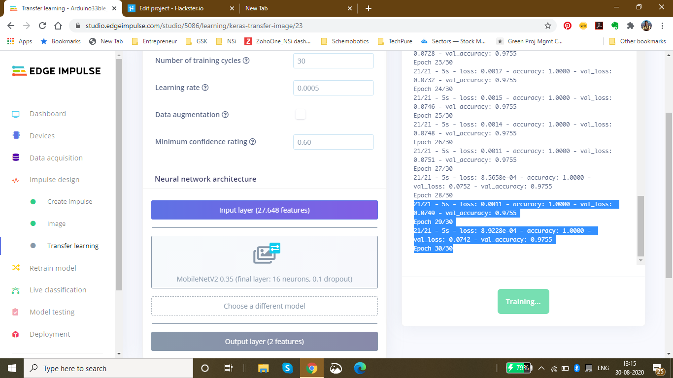
Finally after completing 30 epochs and 10 epochs of best model performance, I got the accuracy heading to 1.00 and the loss nearly 0 which was 0.0011. The following was the ouput during the training process:
Saving best performing model... Converting TensorFlow Lite float32 model... Converting TensorFlow Lite int8 quantized model with float32 input and output...
- Epoch 9/10 21/21 - 5s - loss:0.0011 - accuracy:1.0000 - val_loss:0.0727 - val_accuracy:0.9755
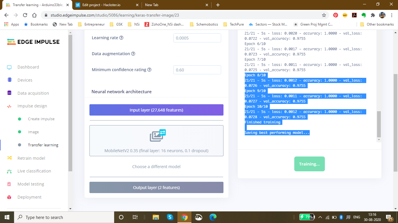
- Epoch 10/10 21/21 - 5s - loss:0.0012 - accuracy:1.0000 - val_loss:0.0728 - val_accuracy:0.9755 Finished training
This was the final output which I received after the training:
The accuracy to be 92.6% and the loss to be 0.19.
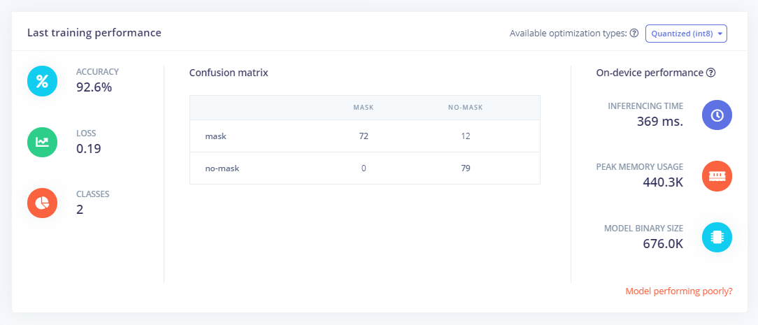
Finally Using the test data, I tested the accuracy and found it to be 98.15%.
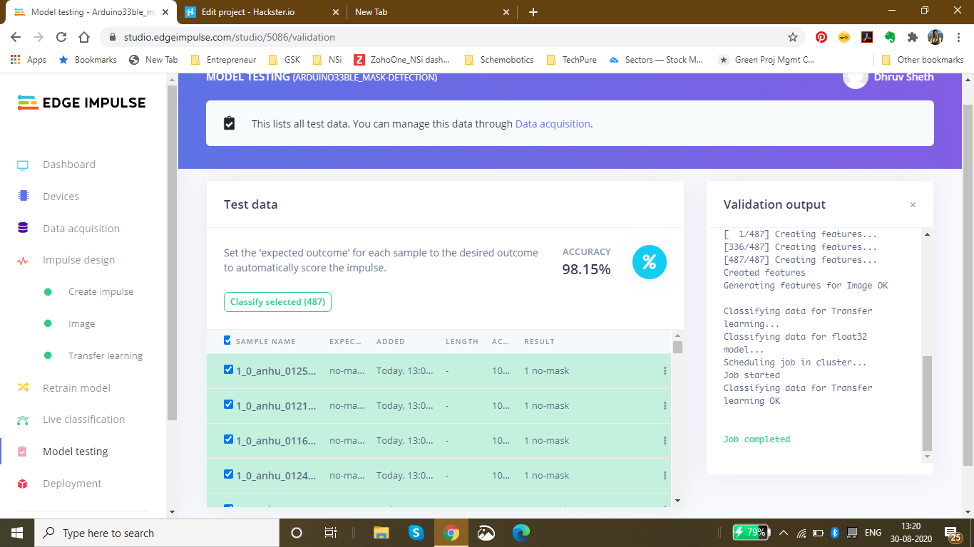
Finally since I had the model ready, I deployed it as an Arduino Library with the firmware to be the Arduino 33 BLE Sense:I got the zip folder of the library ready and started to make changes as per our requirements.
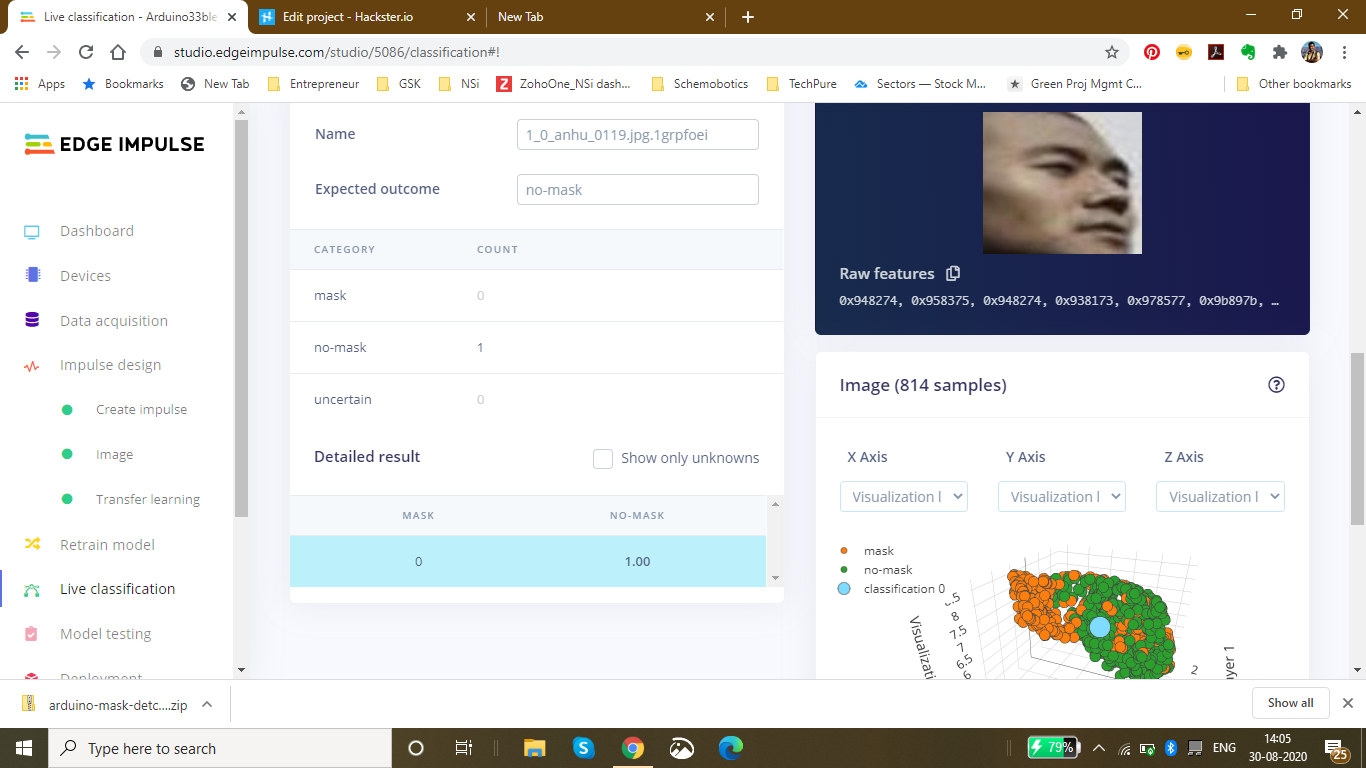
For a last confirmation, I live classified the data to ensure that the data is classified properly. I got the perfect results as expected:
Changing the code as per the output required in the model:
Here is a snippet of the main.ino code of the mask_detection model
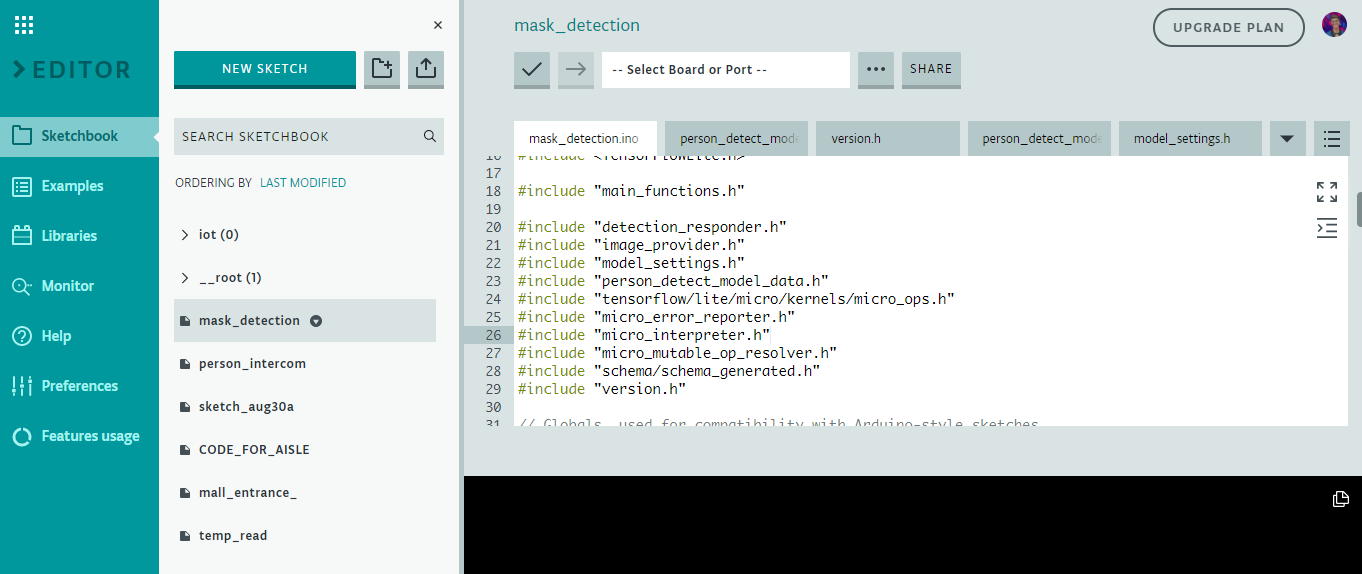
I have defined the arduino libraries required for the functioning of the model and based on the Tensorflow lite framework, I have designed this model.
This is the loop of some of the main functions in the model which are defined in the libraries. The main.ino code centralises these functions and accordingly loops them with a central code.
void loop() {
 // Get image from provider.
 if (kTfLiteOk !=GetImage(error_reporter, kNumCols, kNumRows, kNumChannels,
 input->data.uint8)) {
 TF_LITE_REPORT_ERROR(error_reporter, "Image capture failed.");
 }

 // Run the model on this input and make sure it succeeds.
 if (kTfLiteOk !=interpreter->Invoke()) {
 TF_LITE_REPORT_ERROR(error_reporter, "Invoke failed.");
 }

 TfLiteTensor* output =interpreter->output(0);

 // Process the inference results.
 uint8_t mask_score =output->data.uint8[kmaskIndex];
 uint8_t no_mask_score =output->data.uint8[kno-maskIndex];
 RespondToDetection(error_reporter, mask_score, no_mask_score);
}
The processed data of this model can be viewed here :(This file is relatively large and varies as per the dataset size of the model) Arduino_mask_detect_model_data.h
For providing image, I will be using the Arducam mini 2mp plus for visual data input. A snippet from the image_provider.h file is :
#include "image_provider.h"

/*
 * The sample requires the following third-party libraries to be installed and
 * configured:
 *
 * Arducam
 * -------
 * 1. Download https://github.com/ArduCAM/Arduino and copy its `ArduCAM`
 * subdirectory into `Arduino/libraries`. Commit #e216049 has been tested
 * with this code.
 * 2. Edit `Arduino/libraries/ArduCAM/memorysaver.h` and ensure that
 * "#define OV2640_MINI_2MP_PLUS" is not commented out. Ensure all other
 * defines in the same section are commented out.
 *
 * JPEGDecoder
 * -----------
 * 1. Install "JPEGDecoder" 1.8.0 from the Arduino library manager.
 * 2. Edit "Arduino/Libraries/JPEGDecoder/src/User_Config.h" and comment out
 * "#define LOAD_SD_LIBRARY" and "#define LOAD_SDFAT_LIBRARY".
 */

#if defined(ARDUINO) &&!defined(ARDUINO_ARDUINO_NANO33BLE)
#define ARDUINO_EXCLUDE_CODE
#endif // defined(ARDUINO) &&!defined(ARDUINO_ARDUINO_NANO33BLE)

#ifndef ARDUINO_EXCLUDE_CODE

// Required by Arducam library
#include
#include
#include
// Arducam library
#include
// JPEGDecoder library
#include

// Checks that the Arducam library has been correctly configured
#if !(defined OV2640_MINI_2MP_PLUS)
#error Please select the hardware platform and camera module in the Arduino/libraries/ArduCAM/memorysaver.h
#endif
The Arduino_detection_responder.cpp code performs the inference and delivers the main output required for the code. Here, when a person with a mask is detected, we are opening the gate and if a person with no mask is detected, we are closing the gate.
// Switch on the green LED when a mask is detected,
 // the red when no mask is detected
 if (mask_score> no_mask_score) {
 digitalWrite(LEDG, LOW);
 digitalWrite(LEDR, HIGH);
 servo_8.write(0); // this servo moves to 0degrees in order to open the mall door when a person is detected to ensure no touch entry system
 count++
 } else {
 digitalWrite(LEDG, HIGH);
 digitalWrite(LEDR, LOW);
 servo_8.write(180); // this servo moves to 180degrees when no person is detected
 count2++
 }
The count and count2 are variable integers and increment everytime a mask is detected, or not detected. These counts are then displayed onto the ThingSpeak IoT Dashboard as follows:
The graph displays the mask and no mask count over time. This thingspeak dashboard is setup in the Arduino code as seen here:
#include
#include
WiFiMulti WiFiMulti;
const char* ssid ="Yourssid"; // Your SSID (Name of your WiFi)
const char* password ="Wifipass"; //Your Wifi password
const char* host ="api.thingspeak.com/channels/1118220";
String api_key ="9BRPKINQJJT2WMWP"; // Your API Key provied by thingspeak
The complete code for responder can be viewed here:Arduino_detection_responder.cpp
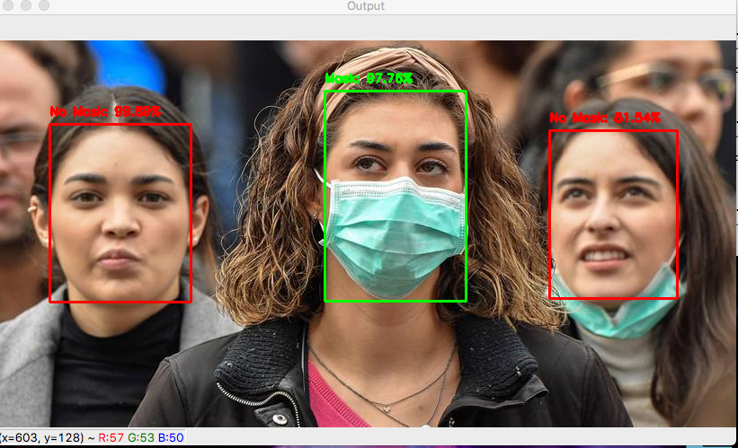
Github Code can be viewed here:Arduino Mask Detetction
The ThingSpeak dashboard can be viewed here - IoT Dashboard
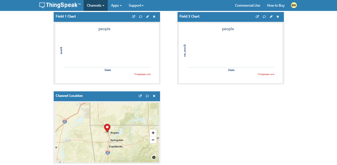
5th project - Person detection in supermarket Aisles and self-sanitisation system:
Just as malls and supermarkets and retail sectors have opened, a risk of contamination of the virus has increased. The main risk that is faced is in supermarkets and stores. The stores could be related to clothes, food and even electronics, the virus could deposit and stay on these surfaces for a long time.
Early data suggests the new coronavirus can live on surfaces for several days
The new coronavirus is, well, new — and there's still much to learn about how easily the virus can spread via contaminated surfaces. But early evidence indicates that the surface survivability of the new coronavirus is similar to that of SARS, a related coronavirus first identified in 2002. Depending on the surface, the virus can live on surfaces for a few hours or up to several days.
The new coronavirus seems to be able to survive the longest on plastic and stainless steel — potentially as long as three days on these surfaces. It can also live on cardboard for up to 24 hours.
Find out what this means for the things you touch throughout the day, including your:
- Clothes
- Food
- Groceries
- Packages
- Electronics
The coronavirus pandemic has breathed new life into a decades-old technique that can zap viruses and bacteria:ultraviolet light.
Hospitals have been using it for years to cut down on the spread of drug-resistant superbugs and to disinfect surgical suites. But there is now interest in using the technology in spaces like schools, office buildings, and restaurants to help reduce coronavirus transmission once public spaces are open again.
The sanitizing effects of UV lights have been seen with other coronaviruses, including the one that causes severe acute respiratory syndrome (SARS). Studies have shown that it can be used against other coronaviruses. One study found at least 15 minutes of UVC exposure inactivated SARS, making it impossible for the virus to replicate. New York's Metropolitan Transit Authority announced the use of UV light on subway cars, buses, technology centers, and offices. The National Academy of Sciences says although there is no concrete evidence for UV’s effectiveness on the virus that causes COVID-19, it has worked on other similar viruses, so it would likely fight this one too.
Abiding by the given information, Malls and Supermarkets have started imposing solutions based on UV sanitisation on manual basis. This consumes a lot of time and also, the data is unavailable. In manual process, one does not know which area has been exposed to human touch more or which are has the highest risk of contamination.
To automate this process and to provide real time spatial analysis of the data collected and the rate of contamination in an area.

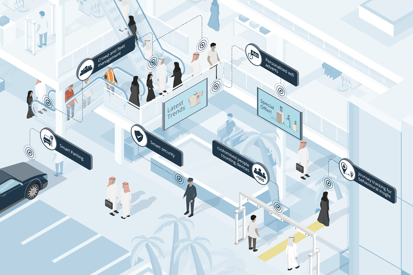
The above images demonstrate the distribution of population across the mall. As it is clearly seen in Figure B, the density near the escalator is comparatively high as compared to the density on the second floor. Manually keeping a track of this continuously changing data in real time and accordingly, sanitising the areas/aisles according to the rate of contamination is not a manual task.
Hence, I decided to make a robust solution for automating this process with the help of TinyML computer Vision &IoT deployed on the Arduino 33 BLE Sense.
The structured framework of this system is as follows:
These models are individually deployed on the Aisles and Areas of the malls and supermarkets close to the Area which has to be sanitised. Since the model utilises person detection Algorithm, the placement of the model is done accordingly.
In this model, for accumulation of Video data, the Arducam mini 2MP Plus is used. The Arducam Mini 2MP Plus continuously gathers visual data and sends this data to the Arduino Nano 33 BLE Sense for processing and classification. The Arduino classifies the data and accordingly processes commands. If a person is detected, the count of people increments by 1 on detection of each person near the Aisle.
A certain threshold for the count of people is set depending upon the rate of contamination based on the object type in that area. The rate of contamination and threshold for food aisle, clothes aisle, sports aisle and Electronic aisle is different.
Accordingly taking into consideration an average threshold, if 25 people are detected, the area is safe. If the count increases to 50, the area is heading towards contamination and the visitors are given an alert. If the count increases to 100, the area is declared contaminated and the people are warned to be careful while touching objects. Finally if the threshold limit is crosses which is 150, the area is autonomously sanitised using UV Light.
The alerts generated are based on LED Colours. Green is an indication for safe, blue is an indication for alert, and Red is an indication for Warning!. These LED based alerts are installed in the respective areas individually.
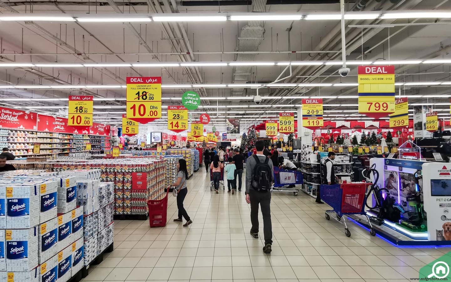
The above image shows the various aisles in the malls where the system can be installed.
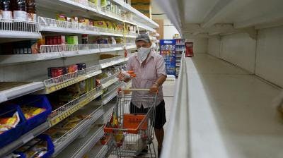
The above image shows the area of installation of Arducam or similar visual data capturing device to cover a wide spectrum of people walking through the aisle.
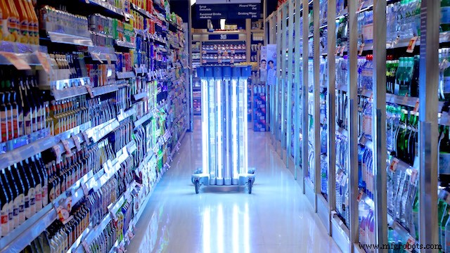

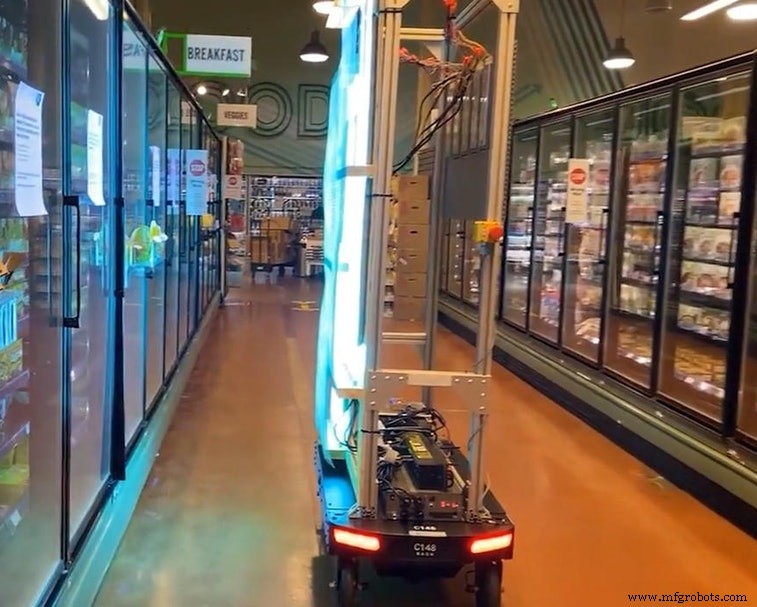
The above Images show a demo implementation of the UV Sanitisation Lights in suitable areas of the aisles. This UV light covers a large spectrum of area that can be sanitised together.
Implementation of the autonomous sanitisation system.
The following Softwares have been used in designing this model:
- TensorFlow lite
- ThingSpeak
- Arduino Web Editor
In this person detection model, I have used the Pre-trained TensorFlow Person detection model apt for the project. This pre-trained model consists of three classes out of which the third class is with undefined set of data:
"unused",
"person",
"notperson"
In our model we have the Arducam Mini 2mp plus to carry out image intake and this image data with a decent rate of fps is sent to the Arduino Nano 33 BLE Sense for processing and and classification. Since the Microcontroller is capable of providing 256kb RAM, we change the image size of each image to a standard 96*96 for processing and classification. The Arduino Tensorflow Lite network consists of a deep learning framework as:
- Depthwise Conv_2D
- Conv_2D
- AVERAGE Pool_2D
- Flatten layer
This deep learning framework is used to train the Person detection model.
The following is the most important function defined while processing outputs on the Microcontroller via Arduino_detetction_responder.cpp
// Process the inference results.
 uint8_t person_score =output->data.uint8[kPersonIndex];
 uint8_t no_person_score =output->data.uint8[kNotAPersonIndex];
 RespondToDetection(error_reporter, person_score, no_person_score);
In the following function defining, the person_score , the no_person_score have been defined on the rate of classification of the data.
using these defined functions, I will be using it to give certain outputs on the basis of confidence of the person_score and the no_person_score .
The detection responder logic of the code works in the following way:
├── Person Detection and sanitisation
├── Arducam mini 2MP Plus
│ ├──Image and Video Data to Arduino
├── Arduino BLE 33 Sense
│ ├── processing and classification of the input data
│ │ ├── If person detected, increment the count by 1
│ │ ├── If no person detected, do nothing
│ │ ├── Send the number of people entered count to to ThingSpeak Dashboard via ESP8266 -01
│ │ | ├── If people count is uptil 25
│ │ │ | ├── Indicate the area to be safe by flashing green light
│ │ | ├── If people count is uptil 50
│ │ │ | ├── Indicate the people to be aware by flashing blue light
│ │ | ├── If people count is uptil 100
│ │ │ | ├── Indicate the area to be contaminated by flashing Red light
│ │ | ├── If people count is between 150 to 175
│ │ │ | ├── Sanitise the area by activating the UV light
│ │ │ | ├── Reset the person count to 0 since the area has been sanitised
│ │ └── ...Repeat the loop
According to the logic used in the model, the Arducam Mini 2MP Plus will continuously capture visual data and send this data to the Arduino Nano 33 BLE sense to process and classify. This model size is 125Kb. Once the image is processed, the Arduino starts to classify the data captured. If a person is detected in the model, the person count increases by 1. This person count is continuously sent to the ThingSpeak dashboard via ESP8266- 01 IoT module. The person count enables the supermarket staff with the data of number of visitors in a particular area at any given point of time. The staff can generate data driven decisions to take action in an area if the visitor count is significantly high.
Proceeding to the output, if the person count is between 1 to 25, the Area is declared safe by flashing the green LED. If the person count is between 26 to 50, the visitors are given an alert by flashing BLUE LED. If the count is between 51 to 100, the area is declared contaminated by flashing the RED LED. When the count surpasses a certain threshold, here taken to be 150, the UV light is turned on until the 165th person passes the area. In this way the Area is sanitised. Similarly the count of people is reset to 0 since the area has been sanitised.
Working of the Firmware:

This model comprises of the following firmware used:
- Arduino 33 BLE sense - Used to process the data gathered, classifies the data processes, sends the command according to the logic fed.
- Arducam Mini 2mp plus - Continuous Raw data image accumulation from source.
- Adafruit lithium ion charger - Used to deliver charge through the lithium battery
- Lithium ion Battery - power source
- ESP8266 - 01 - Used for sending data to the ThingSpeak dashboard via WiFi network.
- RGB LED - Used for flashing Signals based on the status of contamination
- UV Light - Used to Sanitise the Area ( Since this is a prototype, an LED is displayed. In the actual solution, the UV light consumes a lot of energy hence an external power source needs to be provided. )
Functioning and Working of Logic in Code:
The following are the Libraries included in themain.ino c ode for functioning of the model.
#include

#include "main_functions.h"

#include "detection_responder.h"
#include "image_provider.h"
#include "model_settings.h"
#include "person_detect_model_data.h"
#include "tensorflow/lite/micro/kernels/micro_ops.h"
#include "tensorflow/lite/micro/micro_error_reporter.h"
#include "tensorflow/lite/micro/micro_interpreter.h"
#include "tensorflow/lite/micro/micro_mutable_op_resolver.h"
#include "tensorflow/lite/schema/schema_generated.h"
#include "tensorflow/lite/version.h"
The main outcome of the model is dependent on the logic fed in detection_responder.cpp. This snippet shows the generalized threshold of the contamination of the object set to a count of 101.
void RespondToDetection(tflite::ErrorReporter* error_reporter,
 uint8_t person_score, uint8_t no_person_score) {
 static bool is_initialized =false;
 if (!is_initialized) {
 // Pins for the built-in RGB LEDs on the Arduino Nano 33 BLE Sense
 pinMode(LEDR, OUTPUT);
 pinMode(LEDG, OUTPUT);
 pinMode(LEDB, OUTPUT);
 is_initialized =true;
 }

 // Note:The RGB LEDs on the Arduino Nano 33 BLE
 // Sense are on when the pin is LOW, off when HIGH.

 // Switch the person/not person LEDs off
 digitalWrite(LEDG, HIGH);
 digitalWrite(LEDR, HIGH);

 // Flash the blue LED after every inference.
 digitalWrite(LEDB, LOW);
 delay(100);
 digitalWrite(LEDB, HIGH);

 // Switch on the green LED when a person is detected,
 // the red when no person is detected
 if (person_score> no_person_score) {
 digitalWrite(LEDG, LOW);
 digitalWrite(LEDR, HIGH);
 count++
 } else {
 digitalWrite(LEDG, HIGH);
 digitalWrite(LEDR, LOW);
 }

 TF_LITE_REPORT_ERROR(error_reporter, "Person score:%d No person score:%d",
 person_score, no_person_score);
}


 if (constrain(count, 1, 50)) {
 digitalWrite(LEDGREEN, LOW); // This is a green LED which means area is not contaminated yet
}
 if (constrain(count, 51, 75)) {
 digitalWrite(LEDBLUE, LOW); // This is a b led so that people are alert that more than 50 people
}
 if (constrain(count, 76,100)) {
 digitalWrite(LEDRED, LOW); // This is a red LED which warns people that this area is contaminated and one should take care while touching objects
}
 if (constrain(count, 101, 110)) {
 digitalWrite(UV, LOW); // This is an Ultraviolet Light which ensures that after 100 people have touched the aisle objects, it sanitises the area with UV light
 }
 if (count> 111) {
 (count =0); // this resets the person count to 0 once the area has been sanitised by UV light
 }
 } // In this way, a simple math function has been written by me on the arduino nano 33 ble sense which alerts people and sanitizes areas
/* cc - Dhruv Sheth */
The below snippet is carried out by the ESP8266 -01 module to send data to the allocated field in the ThingSpeak Dashboard:
void Send_Data()
{


 // Use WiFiClient class to create TCP connections
 WiFiClient client;

 const int httpPort =80;

 if (!client.connect(host, httpPort)) {
 Serial.println("connection failed");
 return;
 }
 else
 {
 String data_to_send =api_key;
 data_to_send +="&field1=";
 data_to_send +=String(count);
 data_to_send +="\r\n\";

 client.print("POST /update HTTP/1.1\n");
 client.print("Host:api.thingspeak.com\n");
 client.print("Connection:close\n");
 client.print("X-THINGSPEAKAPIKEY:" + api_key + "\n");
 client.print("Content-Type:application/x-www-form-urlencoded\n");
 client.print("Content-Length:");
 client.print(data_to_send.length());
 client.print("\n\n");
 client.print(data_to_send);

 delay(10); // reduced delay to perform real time data collection
 }

 client.stop();

} 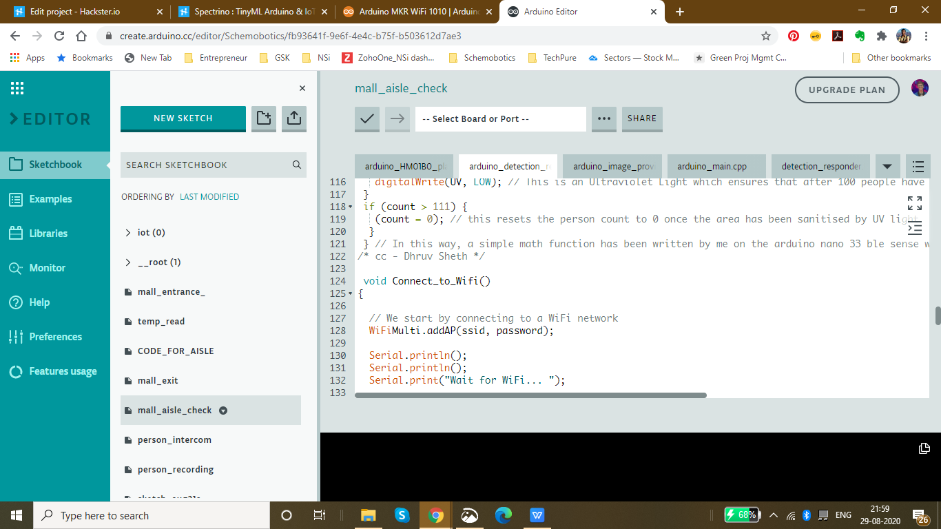
The threshold for each Aisle inside the mall is set to be different according to the rate of contamination of the model. This data can be altered according to the need of the malls or supermarkets. These thresholds can also be altered according to the time trends and the population density in that area.
Threshold set for the Clothes Aisle:
if (constrain(count, 1, 50)) {
 digitalWrite(LEDGREEN, LOW); // This is a green LED which means area is not contaminated yet
}
 if (constrain(count, 51, 75)) {
 digitalWrite(LEDBLUE, LOW); // This is a b led so that people are alert that more than 50 people
}
 if (constrain(count, 76,100)) {
 digitalWrite(LEDRED, LOW); // This is a red LED which warns people that this area is contaminated and one should take care while touching objects
}
 if (constrain(count, 101, 110)) {
 digitalWrite(UV, LOW); // This is an Ultraviolet Light which ensures that after 100 people have touched the aisle objects, it sanitises the area with UV light
 }
 if (count> 111) {
 (count =0); // this resets the person count to 0 once the area has been sanitised by UV light
 }
Threshold for the Electronics Aisle, since the virus stays on these surfaces comparatively less, we have set a higher threshold in this case.
if (constrain(count, 1, 75)) {
 digitalWrite(LEDGREEN, LOW); // This is a green LED which means area is not contaminated yet
}
 if (constrain(count, 76, 180)) {
 digitalWrite(LEDBLUE, LOW); // This is a b led so that people are alert that more than 50 people
}
 if (constrain(count, 181,225)) {
 digitalWrite(LEDRED, LOW); // This is a red LED which warns people that this area is contaminated and one should take care while touching objects
}
 if (constrain(count, 225, 240)) {
 digitalWrite(UV, LOW); // This is an Ultraviolet Light which ensures that after 100 people have touched the aisle objects, it sanitises the area with UV light
 }
 if (count> 111) {
 (count =0); // this resets the person count to 0 once the area has been sanitised by UV light
 }
Threshold set for Food and eatables:, Since these are consumptives, they face a higher risk of contamination. Hence, a lower threshold is set in this case.
if (constrain(count, 1, 25)) {
 digitalWrite(LEDGREEN, LOW); // This is a green LED which means area is not contaminated yet
}
 if (constrain(count, 25, 50)) {
 digitalWrite(LEDBLUE, LOW); // This is a b led so that people are alert that more than 50 people
}
 if (constrain(count, 51,75)) {
 digitalWrite(LEDRED, LOW); // This is a red LED which warns people that this area is contaminated and one should take care while touching objects
}
 if (constrain(count, 76, 90)) {
 digitalWrite(UV, LOW); // This is an Ultraviolet Light which ensures that after 100 people have touched the aisle objects, it sanitises the area with UV light
 }
 if (count> 91) {
 (count =0); // this resets the person count to 0 once the area has been sanitised by UV light
 }
Setting up the Thingspeak IoT Dashboard:
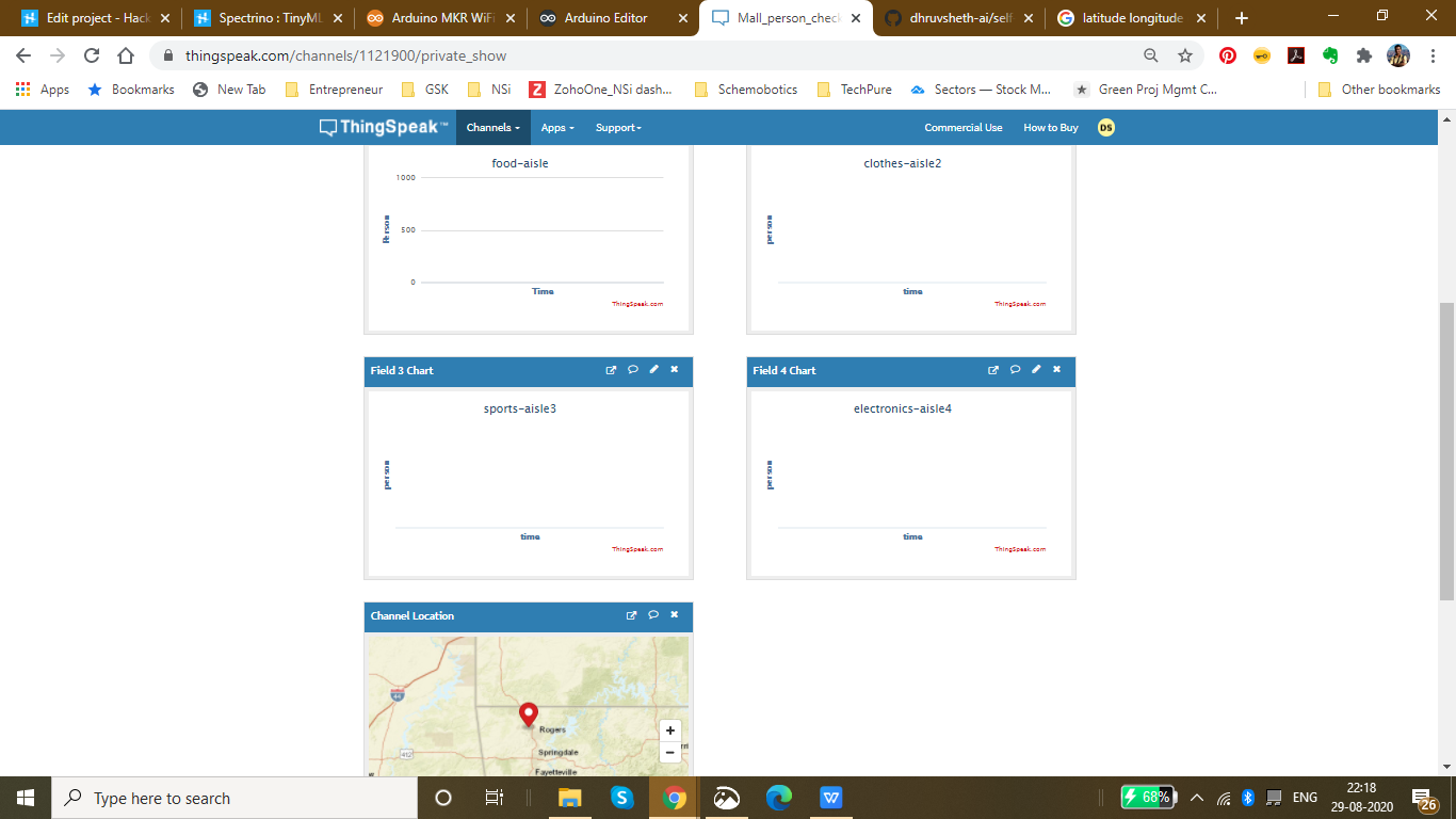
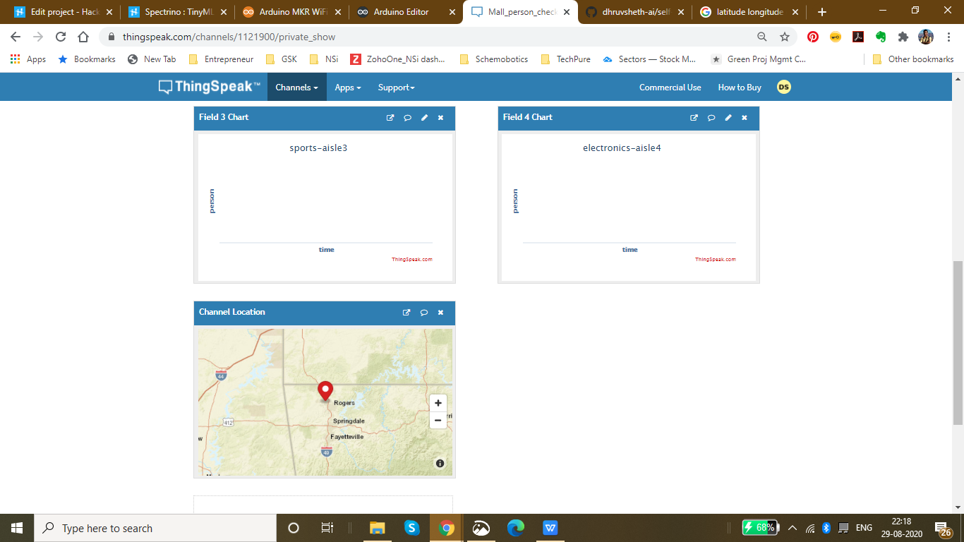
On the thingspeak dashboard, there are 4 fields which have been added for the 4 aisles that have been set up namely:
- Food-aisle
- Sports-aisle
- Clothes-aisle
- Electronics-aisle
The co-ordinate locations of the mall can be seen in the channel visualization which can be cumulatively displayed on a single dashboard through which the data for each supermarket and mall in a locality can be accessed.
The IoT Dashboard can be viewed here:IoT Dashboard
The fields and channels of aisles can be all displayed together on a single Thingspeak IoT Dashboard.
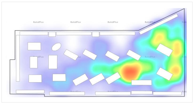
The above image shows a density plot of the density population in a given region in the store of a mall.
Currently I have been using the ThingSpeak Dashboard to plot the data in a graphical format. But, using the same data and Tableau visualizations, it is possible to plot the given data on the floor plot map of the Supermarket.
This data will be easily accessible to other visitors entering the supermarket and will be able to interpret data driven decisions like visiting the store which has a low population density.
Now a question might arise that what makes the product unique:
Currently, the UV sanitisation system is implemented on manual basis and hence the sanitisation system is carried out manually monitoring these areas. Autonomous UV robots are deployed in malls to gather plot data of mall and map these areas, hence autonomously sanitising these areas. These solutions are not capable of sanitising each aisle and area in the mall along with the flowing population of the people in the mall. The sanitisation is only limited to sanitising the lower part of these aisles and hence the upper parts are left unsanitised. These solutions are also comparatively expensive and they are not capable of continuous data monitoring and sanitisation respective to the rate of contamination. This means that they are unable to monitor the number of people who have passes through a certain area or aisle and hence are unable to sanitise areas according to their contamination.
Go to Market and Viability:
- Malls and Supermarkets can use this to identify The count of people in and density of people in a certain area in a store and impose self sanitisation process within the malls.
- Implement Strategies using this data to ensure Safety and Compliance with efficient Population Density monitoring algorithms.
- Decrease Labour and automate Sanitisation process.
- Offer Dashboard to the visitors to monitor the density of people at a certain area inside the mall and accordingly the visitors can have a view of the store with lowest density population and make decisions based on this data. The visitors can also have a view of the timely trends of sanitisation by viewing the abrupt change of person density graph in an area when sanitisation is conducted. ( Since, each time sanitisation in an area takes place, the person count is reset to 0 because the place is sanitised)
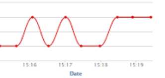
- This product can be used to ensure the visitors that the mall is a safe place and hence, can increase the sales and visits following Government guidelines
- Companies offering Ai and IoT based solutions can invest for mass production and distribution.
- The more the supermarkets using this product, the more the access to data to the government and more the choice to customers to select the preferable safest place in their locality and which store is continuously sanitised to be up to mark in terms of safety. This will lead to a wide range of options of supermarkets in the locality comparing the queue time and safety.
- Comparatively affordable solution as compared to autonomous UV Robot system and highly scalable in terms of data and services with IoT Dashboard provided.
- Utilize real-time CCTV footage to impose autonomous sanitisation system through person detection in terms of timely trends and spatial analysis of person density in the mall.
- Enable Stores to make better, data-driven decisions that ensure your safety and efficient Queues based on autonomous queuing system.
Github Link :https://github.com/dhruvsheth-ai/self-sanitisation-person-detection
PROJECT VIDEO:
Thank you for viewing my project!
Code
- Elevator Automation using "up" - "down" speech command
Elevator Automation using "up" - "down" speech commandArduino
The below is a .zip file of the Arduino LibraryNo preview (download only).
Mall Aisle Self Sanitization with Person Detection System
https://github.com/dhruvsheth-ai/self-sanitisation-person-detetctionTemperature monitoring system based on IoT
https://github.com/dhruvsheth-ai/temperature-arduino-iotMask Detection Algorithm
https://github.com/dhruvsheth-ai/ble-mask-detection-optimisedAutonomous Person Intercom based on TinyML
https://github.com/dhruvsheth-ai/person-autonomous-intercomElevator Automation using TinyML
https://github.com/dhruvsheth-ai/elevator-Automation-ARDUINOMall Entrance Person Detection and Queuing System
Queuing System based on TinyML person detection on Mall Entrance and exit connected via IoT Thingspeak dashboard for Live data monitoringhttps://github.com/dhruvsheth-ai/Person-queuing-system-arduino33Schaltpläne
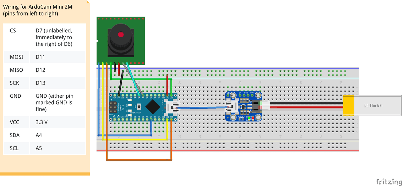
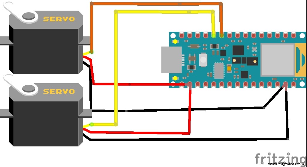
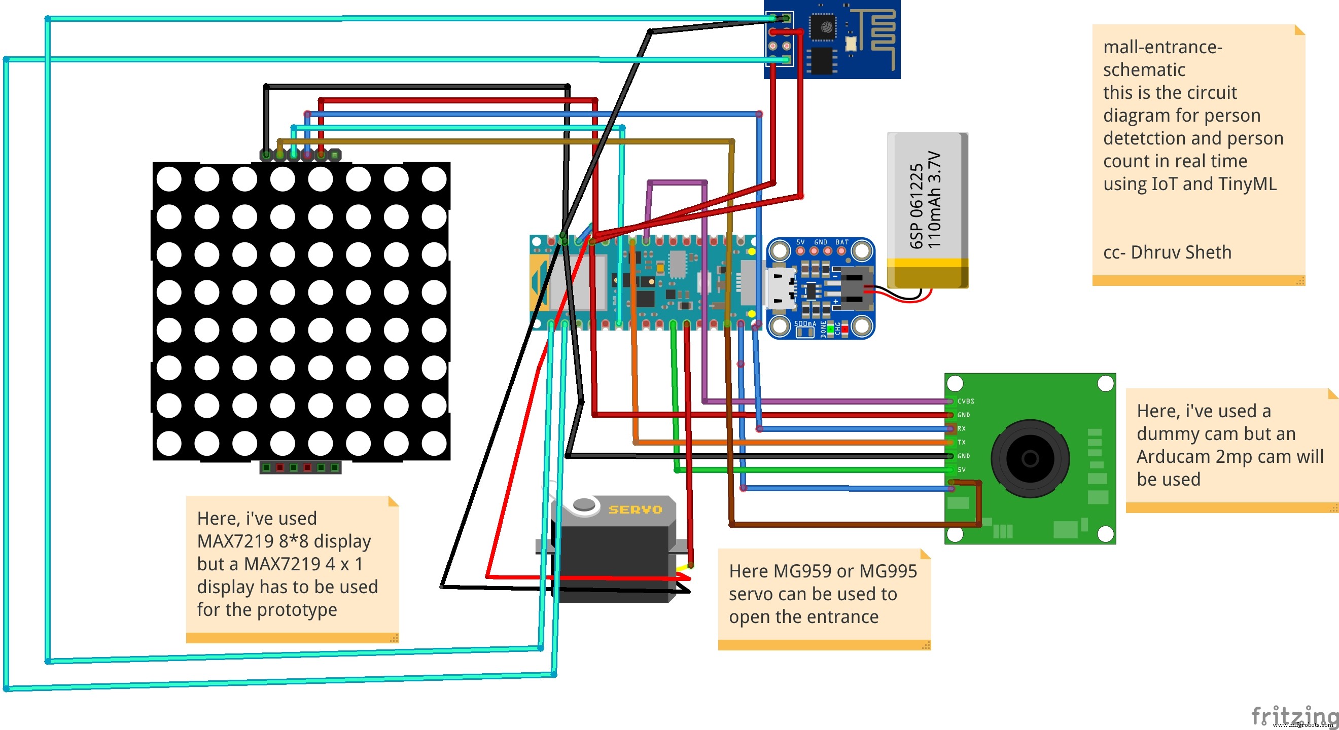 This is the Schematic for the Mall Aisle Person detection and self sanitization system that transfers data to ThingSpeak IoT Dashboard
 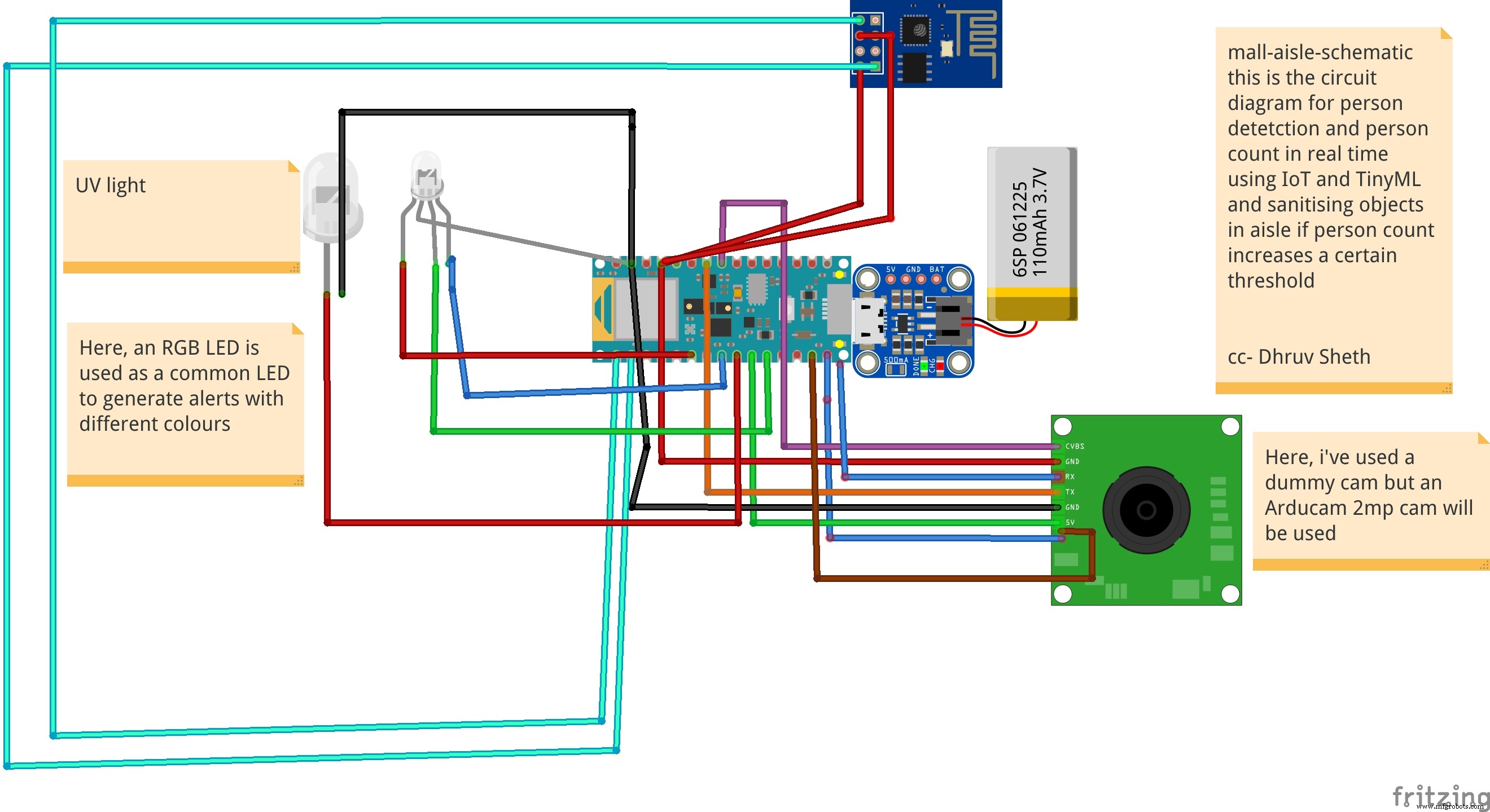 Detects a person present at the door and rings the bell and displays "person" on the LED Matrix as an alternative
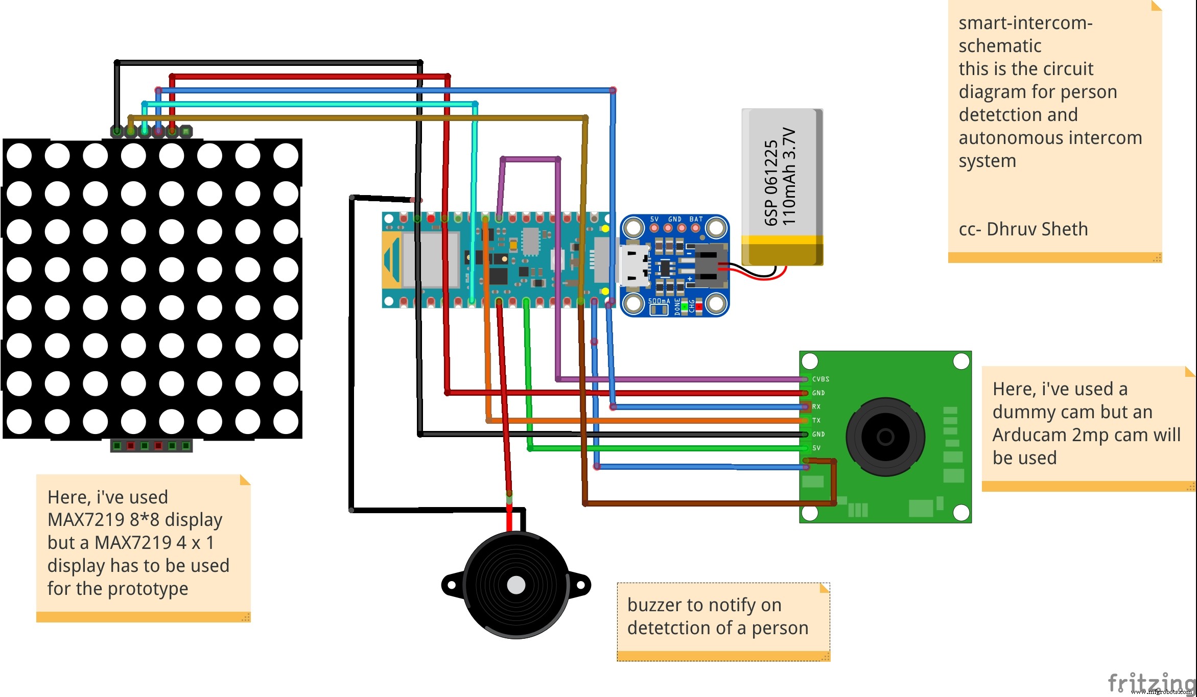
Herstellungsprozess
- Raspberry PI-basiertes IoT-Projekt zum Verbinden des DHT11-Sensors
- Drahtlose Protokolle für IoT-basierte Asset-Tracking-Lösungen
- Arduino Pong-Spiel - OLED-Display
- Herzfrequenzmesser mit IoT
- Pixie:Eine Arduino-basierte NeoPixel-Armbanduhr
- Mit Nextion Display spielen
- Bestimmung der Pflanzengesundheit mit TinyML
- Arduino- und OLED-basierte zelluläre Automaten
- Azure IoT Swimming Pool
- IoT-basierte Lösungen für offene Kombi-Lkw