


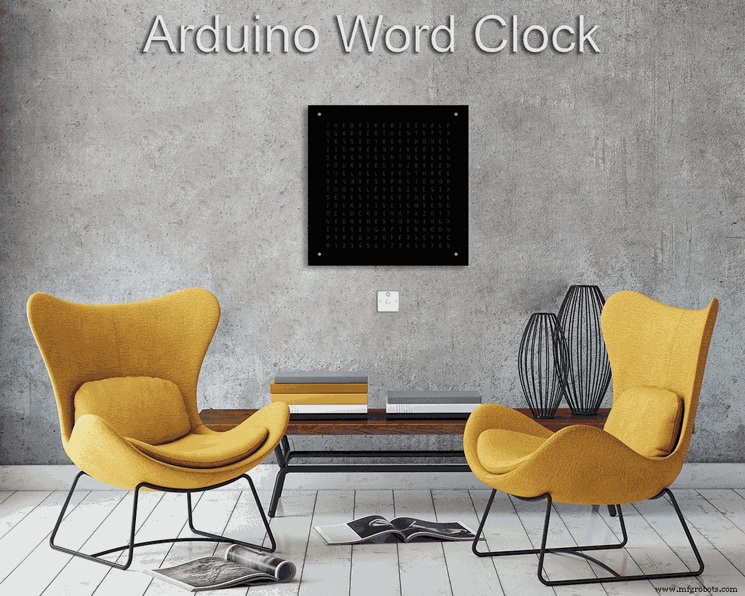
Wortuhr mit Minutenauflösung der Zeit in Worten
Komponenten und Verbrauchsmaterialien
 |
| × | 1 |
Über dieses Projekt
Weitere Details zu diesem Build finden Sie auf meiner Website hier:Word Clock
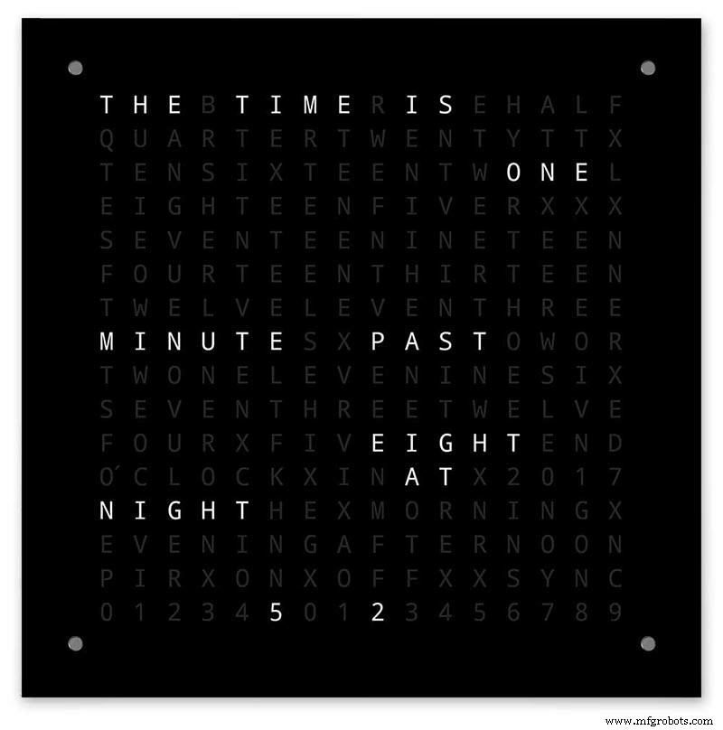
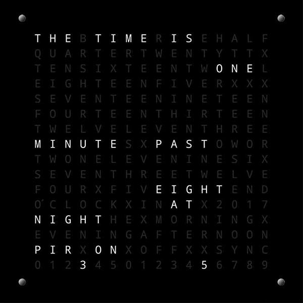
Die Arduino Wordclock mit minutengenauer Zeitauflösung in Worten und linearer Sekundenanzeige.
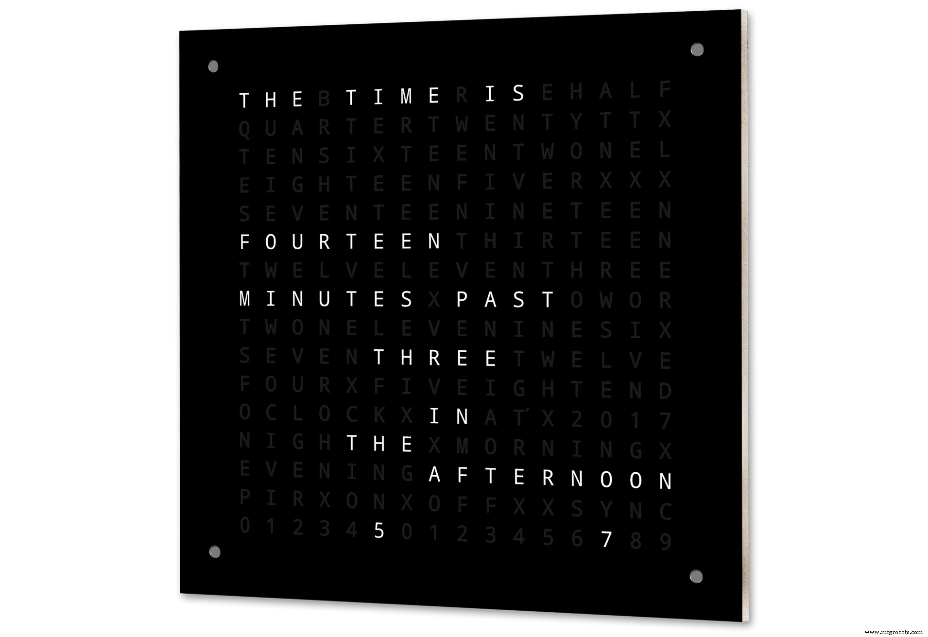
Außerdem gibt es Modi für Digitaluhr, Analoguhr, Temperatur und Luftfeuchtigkeit sowie drei Spiele:Game of Life, Simon und Tetris.
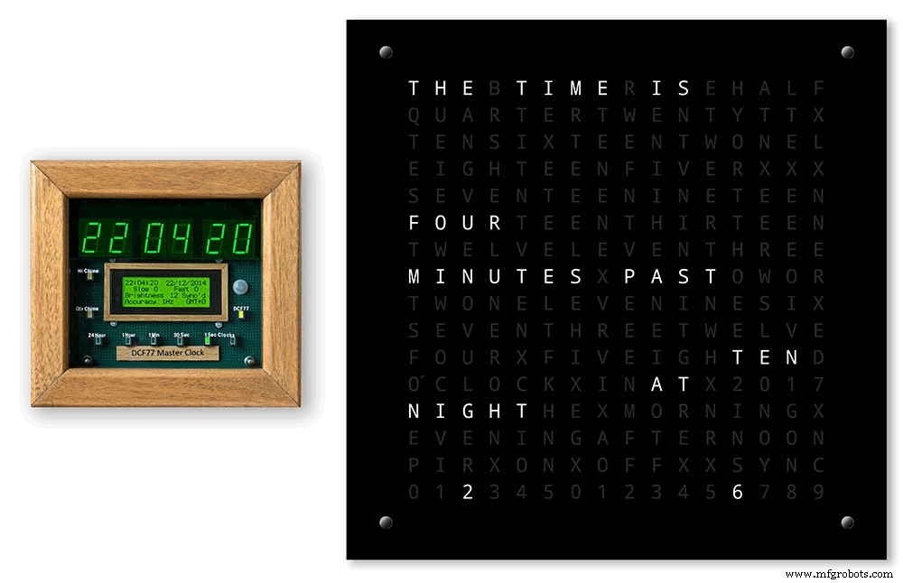
Die Uhr kann bei Bedarf eigenständig oder als Slave von einer Hauptuhr betrieben werden.
Ohne eine Hauptuhr wird die Zeit durch die eingebaute temperaturkompensierte Echtzeituhr der Wordclock gesteuert.
Es gibt eine Option für PIR- oder Doppler-Radarsteuerung, sodass sich die Uhr automatisch ausschaltet, wenn sich niemand im Raum befindet.
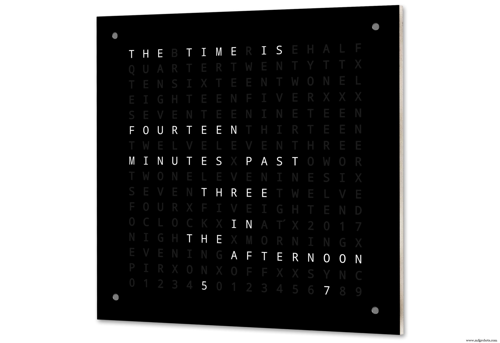
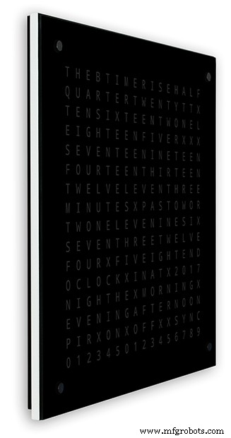
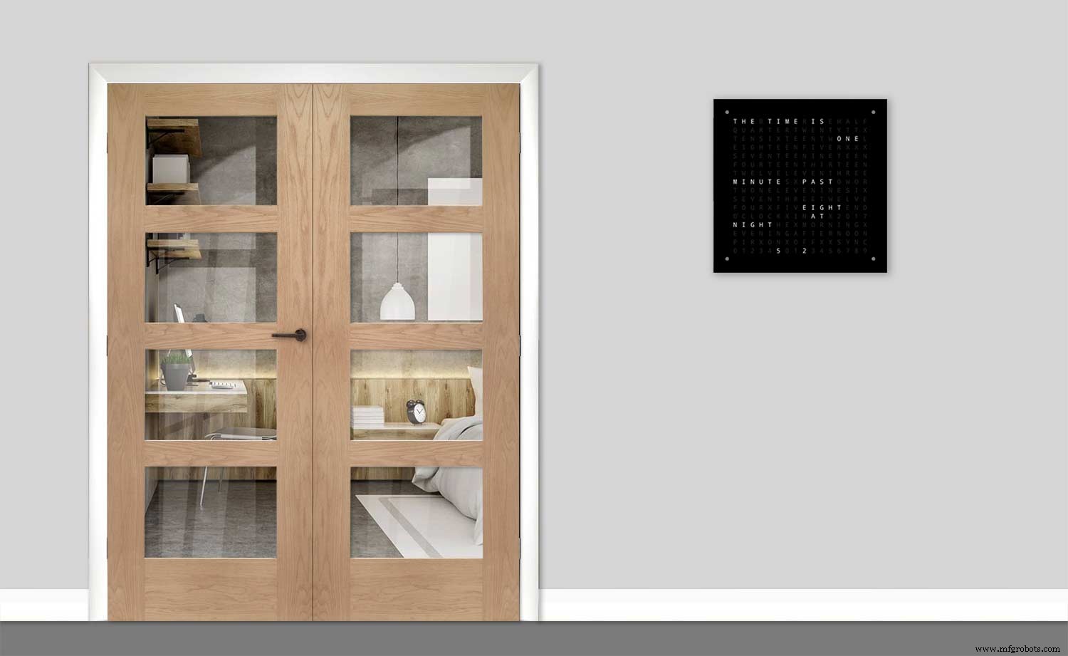
Die Uhr misst 500 mm x 500 mm (19,68" x 19,68"), wiegt 5,5 kg und ist für die Wandmontage konzipiert. In jeder Ecke befinden sich Touchpads zum Einrichten und Steuern der Uhr.
Schritt 1:Über Wordclocks
Über Wordclocks
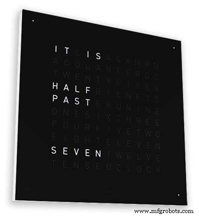
Wortuhren zeigen die Zeit anhand einer Matrix aus Wörtern oder Zahlen und Buchstaben an und gibt es schon seit vielen Jahren. Es gibt einige verschiedene Designtypen, die die Komplexität des Uhrenbaus beeinflussen.
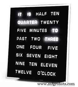
Am einfachsten verwenden Sie Wortblöcke, um die Zeit in einer Auflösung von fünf Minuten anzuzeigen, zB O'CLOCK, 5 PAST, 10 PAST usw. Diese Uhren verwenden nur etwa 20 einzelne LED-Blöcke und sind daher am einfachsten zu konstruieren. Der Hauptnachteil dieser Uhren ist, dass sie die Uhrzeit nur in diesem eingestellten Format anzeigen können.
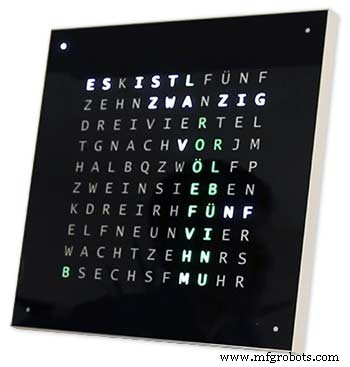
Die mittelgroße Uhr verfügt über eine 11x10-Matrix von LEDs plus vier zusätzliche LEDs um die Außenseite der Uhr. Die vom Raspberry Pi gesteuerte Uhr Photo 2 verfügt sogar über mehrfarbige LEDs und kann mit 110 einzelnen LEDs Ziffern und Grundbilder anzeigen. Diese Uhr verwendet immer noch eine 5-Minuten-Auflösung in Worten, füge jedoch oft "gerade um 5 nach" oder fast 10 zu" hinzu, um die Auflösung leicht zu erhöhen. Oft zeigen die vier LEDs an den Ecken des Rahmens die verstrichenen vier Minuten an, um die Lücke zwischen zu füllen die 5-Minuten-Auflösung. Diese Uhren sind relativ komplex zu bauen und verwenden oft LED-Streifen, um den Bau zu vereinfachen.
Es sind kommerzielle Versionen dieser Art von Uhr erhältlich. Die 450-mm-Wandaufhängungsversion kostet etwa £1000 und verfügt über austauschbare Frontplatten in vielen Farben und Materialien sowie kleinere Tischplatten und Uhren sind erhältlich.
256 Matrix Word Clock von Wouter Devinck
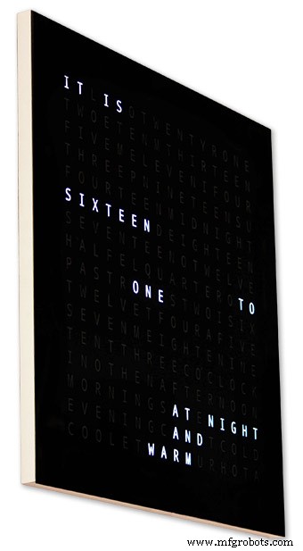
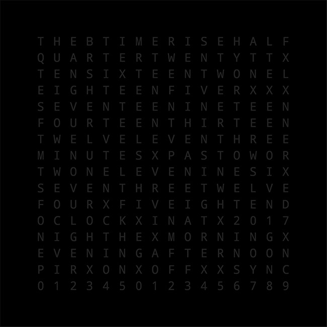
Die Wordclocks mit der höchsten Komplexität verwenden eine 16x16 LED-Matrix, die volle 256 LEDs zur Steuerung bietet. Diese Uhren haben eine einminütige Auflösung der Zeit sowie von Morgen, Abend, Nacht usw. Sie geben oft die ungefähre Temperatur in Worten an wie warm, sehr warm, kalt sehr kalt usw.
Mit den 256 LEDs zum Spielen stehen unzählige verschiedene Anzeigemodi zur Verfügung. Diese Uhren sind aufgrund der Anzahl der Anschlüsse in der Matrixanzeige recht komplex zu bauen. Der Aufbau der LED-Matrix auf Leiterplatten mit oberflächenmontierbaren Komponenten ermöglicht sehr schlanke Uhrengehäuse und vereinfacht die Displaykonstruktion, aber ab 500 mm x 500 mm werden die Leiterplatten teuer.
Der Aufbau der LED-Matrix wie in meiner Uhr von Hand benötigt Platz und 500 mm x 500 mm sind ein guter Ausgangspunkt, da dies gerade die großen Kabelbäume aufnehmen kann, die zum Verbinden der LEDs und Anzeigemodule erforderlich sind. Sehr große Wanduhren können mit handgebauten LED-Matrizen gebaut werden.
Schritt 2:Änderungen
Änderungen
Diese Uhr ist eine Mischung aus der Wouter Devinck Clock Hardware und der "catalan" Pijuana Clock Software. Ich habe keine Leiterplatten verwendet, nur fertige Module und drei kleine Vero-Platinen für die Stromversorgung.
Die wichtigsten Änderungen werden im Folgenden beschrieben.
In dieser Version der Uhr werden keine kundenspezifischen PCBs verwendet, nur billige, einfach zu beschaffende vorgefertigte Module.
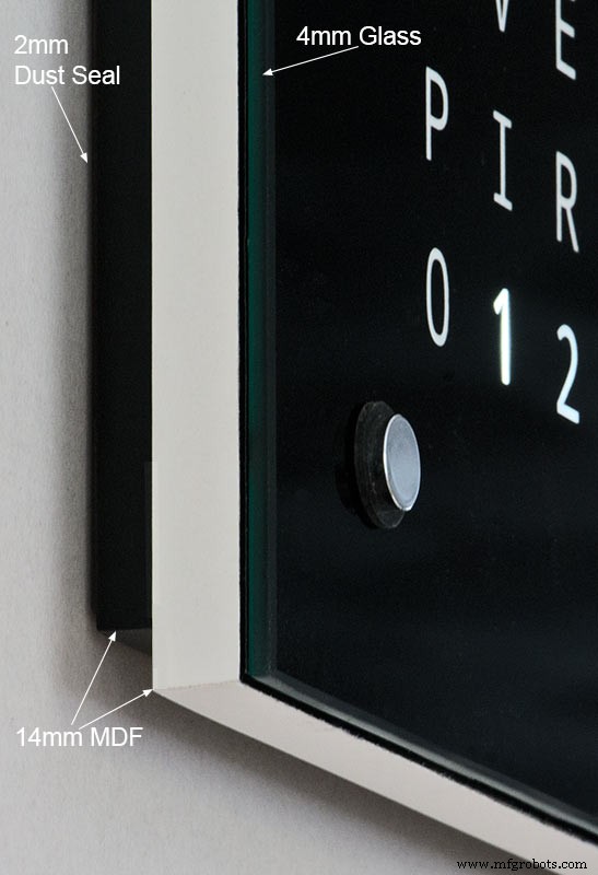
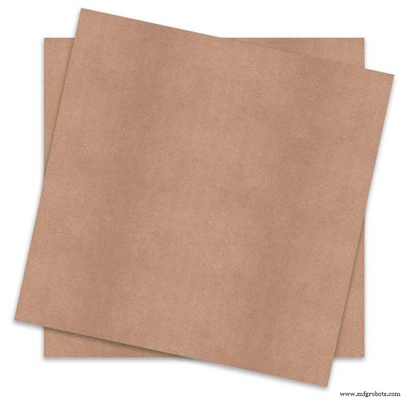
Das Hauptgehäuse der Uhr besteht aus 2 x 14 mm MDF-Platten und nicht aus einem einzelnen 18-mm-Blatt.
Das hintere Blatt ist an allen Seiten außer der Oberseite 10 mm kleiner als das vordere Blatt, sodass die Uhr nur 14 mm dick zu sein scheint.
Die Wouter Devinck Uhr ist nur 20 mm tief, einschließlich des 2 mm Glases, während meine Uhr tatsächlich 34 mm tief ist, einschließlich des 4 mm Glases und der 2 mm Staubdichtung auf der Rückseite. Durch den Rücksprung des hinteren 14mm Panels und den 1,5mm Rücksprung des Glaspanels aus den meisten Blickwinkeln sieht die Uhr nur 14mm tief aus. Diese zusätzliche Tiefe hat es mir ermöglicht, eine handgebaute LED-Matrix und Kabelbäume anstelle von 4 großen Leiterplatten zu verwenden. Es bedeutet auch, dass ich vorgefertigte wartungsfreundliche Module ohne oberflächenmontierbare ICs auf den MAX7219-Boards verwenden kann.
Das Hauptdisplay ist ohne PCB direkt auf die Display-LEDs aufgebaut, sodass Displays jeder Größe möglich sind. TTP223 Berührungssensormodule werden anstelle von Azoteq IQS127D verwendet, das auf den Hauptplatinen montiert ist.
Die Anzeigetreiberplatinen für die MAX7219 I/C verwenden modifizierte LED-Matrixplatinen. Diese Boards werden komplett mit allen Komponenten geliefert.
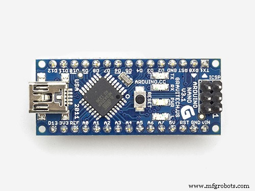
Ein Arduino Nano wird aufgrund seiner geringen Größe zum Antrieb der Uhr verwendet.
Ein PIR-Sensormodul wird verwendet, um das Display auszuschalten, wenn sich niemand im Raum befindet (dies kann deaktiviert werden, damit das Display immer eingeschaltet bleibt).
Der Schaltung wird ein Trimmerwiderstand hinzugefügt, der von der Unterseite der Uhr mit einem kleinen Schlitzschraubendreher zugänglich ist, um die automatische Displayhelligkeit zu kalibrieren.
Synchronisierung mit meinem Hauptuhrensystem jede Minute auf 30 Sekunden. Wenn kein Synchronisationsimpuls verfügbar ist, läuft die Uhr mit der RTC frei. Synchronisationsimpulse werden auf dem Hauptdisplay angezeigt.
Die Software basiert hauptsächlich auf der "katalanischen" Pijuana-Version der Wordclock, so dass diese für die Anzeige ins Englische übersetzt wurde. Die Credits-Anzeige wurde gegenüber der "katalanischen" Pijuana"-Version geändert, um die aktuelle Softwareversionsnummer, meinen Namen und auch das Baujahr anzuzeigen.
Die Temperaturangabe wurde aus der Uhranzeige entfernt und eine lineare Sekundenanzeige in der unteren Reihe der Wort-, Digital- und Analoguhren hinzugefügt.
Wenn PIR ein- oder ausgeschaltet wird, wird "PIR ON" oder "PIR OFF" für einige Sekunden auf dem Wordclock-Display angezeigt.
Diese Uhr verwendet ein DS3231 AT24C32 I2C Precision Real Time Clock Module gemäß der Wouter Devinck Clock und der "katalanischen" Pijuana-Uhr. Den mitgelieferten Lithium-Ionen-Akku verwende ich nicht gerne. Ich verwende einen nicht wiederaufladbaren Akku und habe das Modul entsprechend modifiziert.
4mm Floatglas mit polierten Kanten ersetzt das 2mm Glas. Das Glas wird mit Chicago Fasteners anstelle von Leim auf der Haupt-MDF-Platte befestigt. Diese fungieren auch als Touchpads zur Steuerung der Uhr und ermöglichen das Entfernen des Glases bei Bedarf.
In die Uhr sind zwei Staubdichtungen eingebaut, eine auf der Rückseite und eine hinter dem abnehmbaren Glasdisplay. Wenn Sie im Uhreinstellungsmodus die Taste BOT Right drücken, werden die Sekunden jetzt auf 0 zurückgesetzt.
Die folgenden Änderungen am englischen Wortlaut wurden vorgenommen, um den Wortlaut so zu gestalten, wie ich ihn sagen würde. Die Art und Weise, wie die Leute sagen, dass die Zeit von Region zu Region unterschiedlich ist, hängt davon ab, wo Sie leben/zur Schule gegangen sind usw. Es gibt keinen richtigen Weg, nur die Art und Weise, die für Sie am besten klingt.
Die Wörter, die die Temperatur auf der Wordclock anzeigen, wurden entfernt. Diese wurden durch Sync-Status, PIR ON/OFF und lineare Sekundenanzeige ersetzt.
"MINUTES" zu "MINUTE" geändert um 1 Minute nach und 1 Minute auf die Stunde.
Ein "A" vor dem "VIERTEL" und "VIERTEL" vor der Stunde hinzugefügt.
Das fehlende "ELEVEN" von Wouter Devinck Uhr gemäß seinen Notizen hinzugefügt.
Um Mittag änderte sich die Uhrzeit auf ZWÖLF UHR AM NACHMITTAG.
Um Mitternacht änderte sich die Uhrzeit auf ZWÖLF UHR NACHT. Nach Mitternacht wird die Uhr immer AM MORGEN anzeigen.
Das "O'CLOCK" ist jetzt nicht interpunktiert und zeigt nur UHR an.
Schritt 3:Gehäusedesign
Da meine Uhr keine benutzerdefinierten Display-Matrix-Platinen mit oberflächenmontierten Komponenten verwendet, muss mein Uhrengehäuse etwas tiefer sein als das Design von Wouter.
Mein Gehäuse ist 34 mm tief und enthält die hintere Staubdichtung 2 mm, die hintere MDF-Platte 14 mm, die vordere Anzeigetafel 14 mm und 4 mm Floatglas.
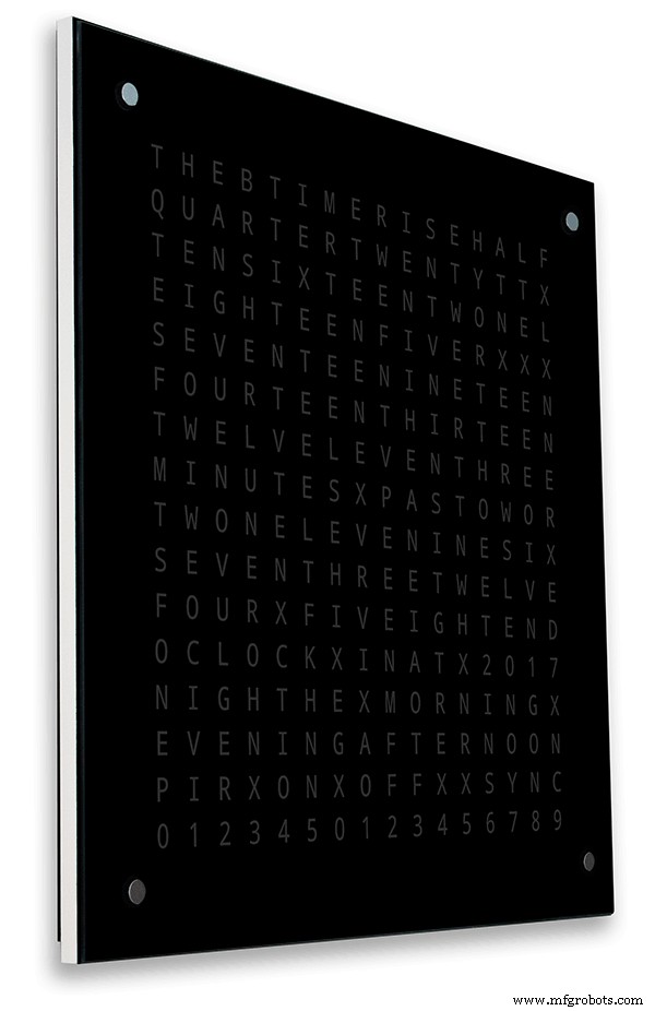
Wouters Gehäuse rechts ist nur 21 mm tief, hat eine einzelne MDF-Platte von 18 mm und 2 mm Floatglas.
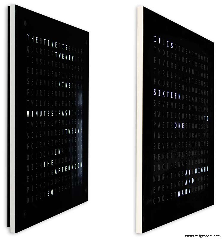
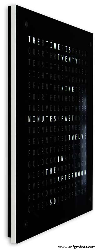
Damit meine Uhr bei der Wandmontage für das Auge weniger sperrig erscheint, habe ich ein paar einfache Designmerkmale eingebaut. Bild oben zeigt links meine Uhr und rechts Wouters Uhr. Aus einer extremen Seitenansicht können Sie deutlich sehen, dass mein Gehäuse sperriger aussieht.
Dies wird etwas dadurch ausgeglichen, dass die hintere Platine eher schwarz als weiß ist, wodurch sich Ihr Auge auf die schlanke weiße 14-mm-Kante konzentriert. Das hintere Board ist unten und an beiden Seiten 10 mm kürzer und verstärkt diese Illusion.
Oben - links wieder meine Uhr und rechts Wouters Uhr. Je weiter man sich vor die Uhren bewegt, desto kürzer wird das hintere Board meiner Uhr, bis nur noch das schlanke 14mm-Frontboard sichtbar ist. Das 4mm Glas ist auch 1-2mm kürzer geschnitten als das Frontboard, um es vor den Blicken zu verbergen . Mein sperriges 34-mm-Uhrengehäuse scheint jetzt so schlank zu sein wie das von Wouter.
Schritt 4:Steuerung
Steuerung

Auf der Uhr, oben links, oben rechts, unten links und unten rechts auf dem Display befinden sich TTP223-Touch-Control-Module.
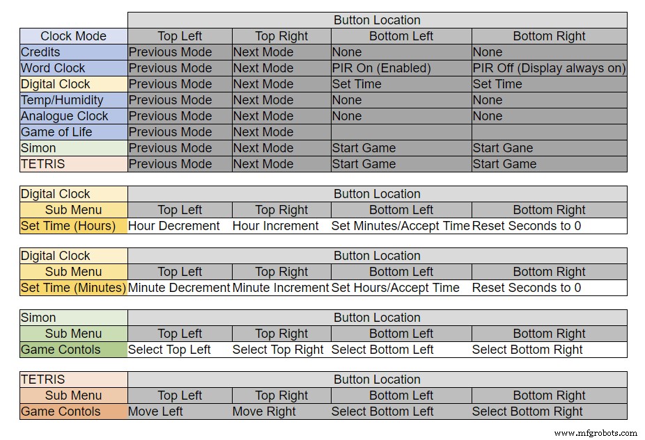
Die Tasten haben je nach Modus der Uhr unterschiedliche Funktionen, siehe Tabelle oben.
Schritt 5:Automatische Sommer-Winter-Einstellung
Nicht verwendet.
Schritt 6:Anzeigemodi Uhren &Umgebung
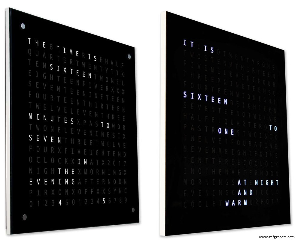
Animation 1 oben zeigt die 4 Uhr- und Umgebungsmodi.
Die Modi sind Wordclock, Digitaluhr, Temperatur und Luftfeuchtigkeit und Analoguhr.
Animation 2 oben. Es gibt auch einen Startmodus, der durch die Softwareversionsnummer, den Herstellernamen und den Namen der Uhr scrollt.
Schritt 7:Anzeigemodi Spiele
Drei klassische Spiele sind in der Uhr codiert. Ich habe den Code der katalanischen Uhr unverändert gelassen.

Animation 1 über Conways Spiel des Lebens. Das Universum des Spiels des Lebens ist ein unendliches zweidimensionales orthogonales Gitter aus quadratischen Zellen, von denen sich jede in einem von zwei möglichen Zuständen befindet, lebendig oder tot, oder "bevölkert" oder "unbevölkert".
Jede Zelle interagiert mit ihren acht Nachbarn, dh den Zellen, die horizontal, vertikal oder diagonal benachbart sind. Bei jedem Zeitschritt treten die folgenden Übergänge auf:Jede lebende Zelle mit weniger als zwei lebenden Nachbarn stirbt, als ob sie durch Unterbevölkerung verursacht worden wäre. Jede lebende Zelle mit zwei oder drei lebenden Nachbarn überlebt die nächste Generation. Jede lebende Zelle mit mehr als drei lebenden Nachbarn stirbt wie durch Überbevölkerung. Jede tote Zelle mit genau drei lebenden Nachbarn wird wie durch Reproduktion zu einer lebenden Zelle.
Das Anfangsmuster bildet den Keim des Systems. Die erste Generation entsteht durch gleichzeitiges Anwenden der obigen Regeln auf jede Zelle in der Saat. Geburten und Todesfälle treten gleichzeitig auf, und der diskrete Moment, in dem dies geschieht, wird manchmal als Tick bezeichnet (mit anderen Worten, jede Generation ist eine reine Funktion der vorherigen eins). Die Regeln werden weiterhin wiederholt angewendet, um weitere Generationen zu schaffen.
Animation 2 über Simon
Simon Memory-Spiel – versuche die computergenerierte Sequenz und kopiere sie. Wenn du deine Sequenz eingibst, tippe doppelt auf den letzten Eintrag, um deinen Zug zu beenden.
Wenn Sie durchfallen, wird Ihre Punktzahl auf dem Bildschirm angezeigt.
Animation 3 über TetrisTetris ist das sowjetische Puzzle-Videospiel zum Abgleichen von Kacheln, das im Juni 1984 veröffentlicht wurde. Dieses Spiel muss noch etwas an den Tasten arbeiten, um die Kacheln richtig zu steuern.
Schritt 8:Prototyping
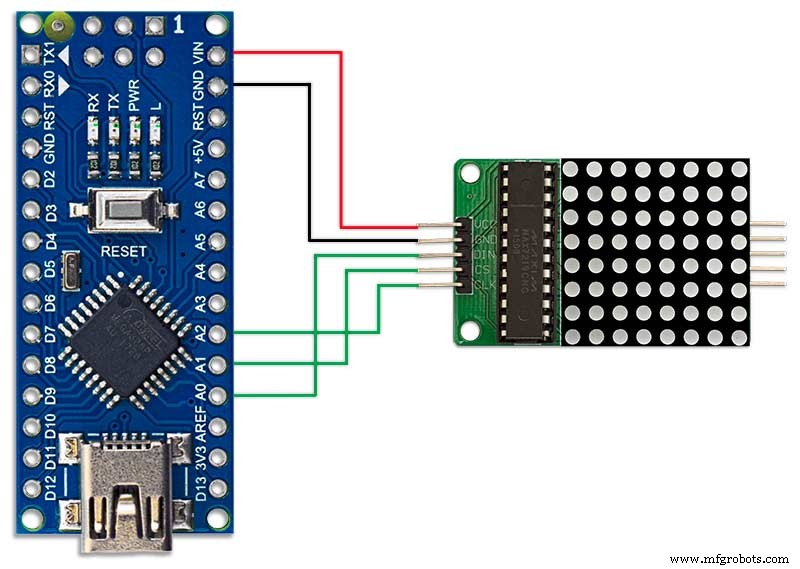
Die Uhr kann mit den originalen DOT-Matrix-LEDs auf den MAX7219-Anzeigetafeln als Prototyp hergestellt und getestet werden.
Beachten Sie, dass diese vorübergehende Änderung nur erforderlich ist, wenn Sie Ihren Code auf den DOT-Matrix-Displays testen möchten, die mit den MAX7219-Modulen geliefert werden.
Dies bedeutet, dass Sie Ihre Software-/Wort-Layout-Modifikationen im Miniaturformat ausprobieren können, bevor Sie sich auf die Vollversion festlegen. Die Verkabelung zur DOT-Matrix-LED muss an die Softwareanschlüsse angepasst werden.
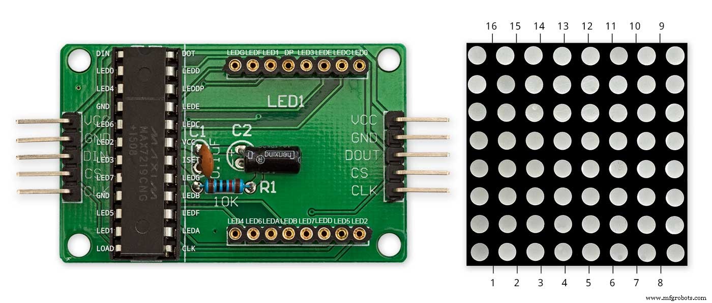
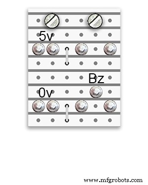
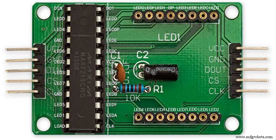
Das Bild oben zeigt, wie das Modul vor der Modifikation verdrahtet wird. Die Modifikation ist ganz einfach. Biegen Sie zunächst die folgenden LED-Matrix-Pins um 90°, die oberen Pins nach oben und die unteren Pins nach unten.
Stifte 16, 15, 3, 4, 10 &11.
Stecken Sie die LED-Matrix in die Buchse auf der Display-Platine, die obigen Pins werden jetzt nicht verbunden. Löten Sie die folgenden Verbindungsdrähte von der Rückseite des Sockels der Display-Platine auf die herausstehenden LED-Matrix-Pins.
LEDA zu Punktmatrix Pin 16
LEDB zu Punktmatrix Pin 15
LEDG zu Punktmatrix Pin 3
LEDF zu Punktmatrix Pin 4
LEDE zu Punktmatrix Pin 10
LEDC zu Punktmatrix Pin 11
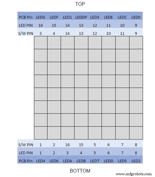
Ich benutzte ein Multimeter und summte das Anzeigemodul aus. Die Tabelle zeigt, wo sich die Software-Pin-Nummern von den LED-Pin-Nummern auf der Anzeigetafel unterscheiden.
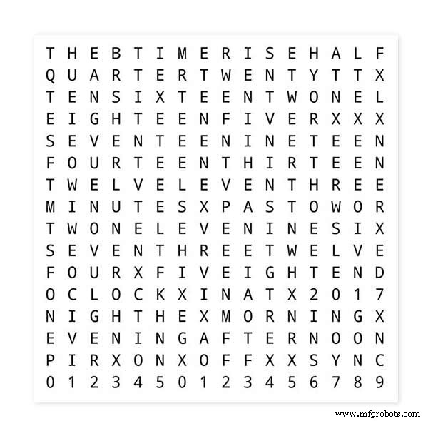
Um Ihre Wort-Layouts zu testen, drucken Sie eine Miniaturversion Ihres Wort-Displays 62 mm x 62 mm auf weißem Normalpapier aus.
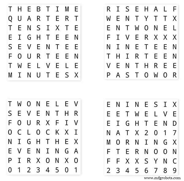
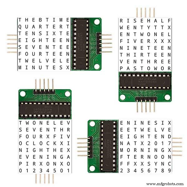
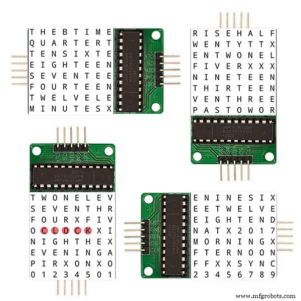
Beachten Sie die Ausrichtung der LED-Anzeigetafeln entsprechend dem Software-Layout.
Ich habe die Displaydrehung wie die ursprüngliche Wouter Devinck Uhr beibehalten, falls jemand das Wouter Devinck PCB-Design für meine Uhr verwendet.
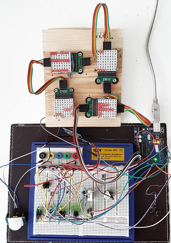
Der kleine Druckknopf unter dem Temperatur-/Feuchtesensor dient zum Testen der 30-Sekunden-Synchronisation. Die Touch-Button-Module sind unten links am Steckbrett seitlich angebracht. Bei diesem Prototyp gibt es nicht viele Drähte, da sich die meisten Drähte in den Anzeigematrizen befinden. Bei der letzten Uhr wird diese Verdrahtung zu den einzelnen LEDs von Hand durchgeführt.
Ich habe viele verschiedene Word/Clock-Designs auf diesem Board ausprobiert, bevor ich versucht habe, die endgültige Uhr zu bauen.
Schritt 9:Testen der modifizierten Module
Ich habe die Wordclock-Skizze modifiziert, damit das MAX2719-Modul nach dem Verdrahtungsmod getestet werden kann.
All dieses Programm beleuchtet jede LED der Reihe nach von oben links nach unten rechts in der Matrix.
Schließen Sie einfach 5 Drähte an das NANO- und MAX2719-Modul an und versorgen Sie das NANO über seinen USB-Port. Laden Sie die Skizze und lassen Sie sie laufen.
Stecken Sie einfach jedes Modul nacheinander ein, um Ihre Verkabelung zu überprüfen.
Laden Sie die Testskizze aus der beiliegenden Zip-Datei herunter.
MAX7219_LED_Test.zip
Schritt 10:Zeit-zu-Wort-Zuordnung
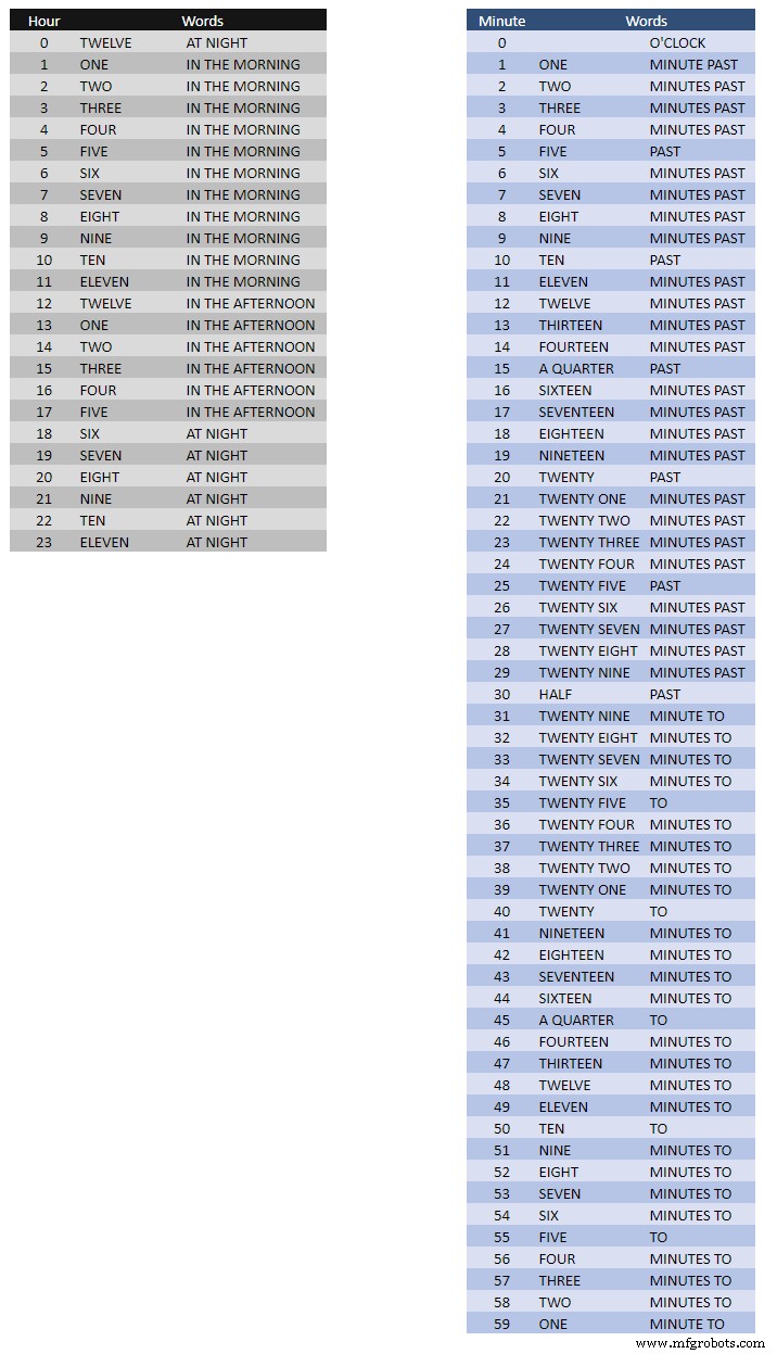
Die obige Tabelle zeigt die Zeit-zu-Wort-Zuordnungen.
Dafür gibt es keine festen Regeln, sondern legen Sie die Worte so fest, wie Sie die Uhrzeit angeben würden.
In meiner Uhr habe ich folgendes gegenüber den Wörtern auf Wouters Uhr geändert.
"MINUTES" wurde um 1 Minute nach "MINUTE" und 1 Minute auf die Stunde geändert. Ein "A" vor dem "VIERTEL" und "VIERTEL" zur Stunde hinzugefügt.
Um Mittag änderte sich die Uhrzeit auf ZWÖLF UHR AM NACHMITTAG.
Um Mitternacht änderte sich die Uhrzeit auf ZWÖLF UHR NACHT.
Nach Mitternacht wird die Uhr immer AM MORGEN anzeigen.
Diese Änderungen sind in der Uhrensoftware sehr einfach zu implementieren.
Word%2Bto%2BTime%2BTranslations.xlsx
Schritt 11:Leistung
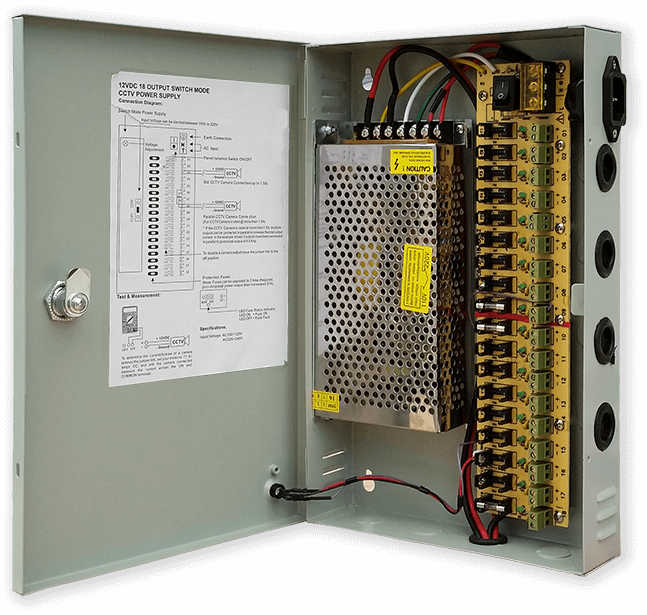
Ich verwende ein gemeinsames 12-Volt-Netzteil, um viele verschiedene Arten von Stromkreisen in meinem ganzen Haus zu betreiben. Diese 12-Volt-Versorgung wird dann lokal an jedem Stromkreis mit einem 5-Volt-Modul heruntergesetzt, um die Steuerplatine und verschiedene Module mit Strom zu versorgen.
Mein gemeinsames Netzteil hat 18 einzeln abgesicherte 12-V-Stromkreise mit jeweils einer 2 A-Sicherung. 9 davon sind batteriegepuffert. Uhrenplatinen haben auch ihre eigene On-Board-Sicherung.
Wenn Sie nur diesen einen Stromkreis betreiben, reicht jede geregelte 5-Volt-Versorgung, solange sie den Strom für Ihren Stromkreis liefern kann.
Ich habe auf Vero eine Stromversorgungsplatine entworfen, die ein MP1584-Miniaturnetzteil verwendet. Dies wandelt den 12-V-Ausgang meines gemeinsamen Netzteils in 5 V für die Uhr um.
Es gibt zwei zusätzliche Leistungsplatinen aus Vero-Platine.
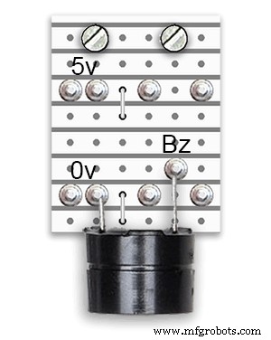
Abgesehen davon, dass 1 den Summer hält, fügen sie nur zusätzliche Stromverteilungspunkte für die Stromverkabelung der Uhr hinzu.
Strombedarf
Ich habe die Stromaufnahme von der Uhr gemessen und bei geringer Helligkeit verwendet sie 30 mA und volle Helligkeit 250 mA. Dies hängt natürlich davon ab, wie viele LEDs eingeschaltet sind. An einem hellen sonnigen Tag beträgt die auf dem seriellen Ausgang angezeigte Helligkeit 10. Dies sind etwa 2 Drittel der maximalen Leistung der LEDs. Der Gesamtstromverbrauch kann stark reduziert werden, wenn der PIR eingeschaltet ist. Dadurch wird das Display ausgeblendet, wenn die Uhr keine Bewegung erkennt.
Ich würde eine Stromversorgung von mindestens 500 mA verwenden, um die Uhr mit Strom zu versorgen. Die Leistung hängt stark von der Art der LEDs ab, die Sie beziehen.
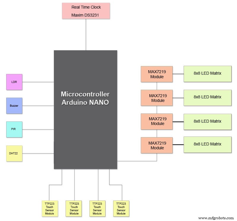
Schritt 12:Modulverbindungen
Bild oben zeigt, wie die Module verbunden sind. Die meisten Module werden direkt mit dem Arduino Nano verbunden.
Die MAX7219-Boards werden nur über das Modul 01 mit dem NANO verbunden. Die anderen Module sind miteinander verkettet.
Jede 8x8 LED-Matrix wird dann mit einem MAX7219-Modul verbunden.
Der Großteil der Verkabelung sind die Verbindungen zwischen den MAX7219-Modulen und den LED-Matrizen.
Halten Sie den Abstand zwischen NANO und dem 1. MAX7219-Modul und MAX7219-Modul zu Modulen so gering wie möglich. Stellen Sie außerdem sicher, dass beide Enden der verketteten MAX7219 mit Strom versorgt werden, da der Großteil der Leistung von diesem Teil der Schaltung gezogen wird.
Schritt 13:Baureihenfolge des Builds
Baureihenfolge unter der Annahme, dass alle Prototyping- und Softwareänderungen zuerst abgeschlossen werden.
Lassen Sie Vinyl-Transfer drucken.
Glas schneiden lassen.
Schneiden Sie MDF-Platten vorne und hinten.
Schneiden Sie Löcher in die Frontfolie für LEDs.
MDF-Platten bemalen.
Schneiden Sie Löcher für Sensoren in Glas.
Kleben Sie das Vinyl-Transfer auf die Rückseite des Glases.
Schneiden Sie die Sensorlöcher in die MDF-Frontplatte.
Sensormodul-Falzungen in Frontplatte schneiden.
Schneiden Sie die MDF-Rückwand zu und machen Sie 4 Zugangslöcher für den Sensorzugang.
Fügen Sie Melaminkantenstreifen zu MDF-Platten hinzu, Weiß zu Vorderplatte und Schwarz zu Rückplatte.
MDF-Platte hinten an MDF-Frontplatte anschrauben.
Stellen Sie Vero-Boards, 1 Power Board und 2 Power Distribution Boards her.
Modifizieren Sie 4 x MAX7219-Platinen und fügen Sie LEDs eine Verkabelung hinzu.
Verbinden Sie sich vorerst nur am MAX7219-Ende.
Montieren Sie alle Module und Vero-Platinen auf der Rückseite der MDF-Frontplatte.
Konstruieren Sie alle 4 LED-Matrizen auf der vorderen MDF-Platine und löten Sie 256 LEDs.
Verdrahten Sie alle Batt- und Erdungsleitungen von der Vero-Stromversorgungsplatine und den Stromverteilungsplatinen.
Schließen Sie alle Stromleitungen an alle Module an.
Schließen Sie alle Kabel an Nano, MAX7219-Module, RTC, Temperatursensor, Berührungssensoren und Summer an.
Schließen Sie alle Kabelbäume von modifizierten MAX7219-Platinen an LED-Matrizen gemäß der Verdrahtungstabelle an.
Schließen Sie ein PIR-Modul aus der Ferne von der Uhr an und verbinden Sie die PIR-Verbindung.
Verbinden Sie die 30-Sekunden-Synchronisierung mit Ihrer Master Clock (falls erforderlich).
Montieren Sie das Glas-Frontdisplay mit den Chicago-Schrauben und befestigen Sie gleichzeitig die Berührungssensoren.
Testen.
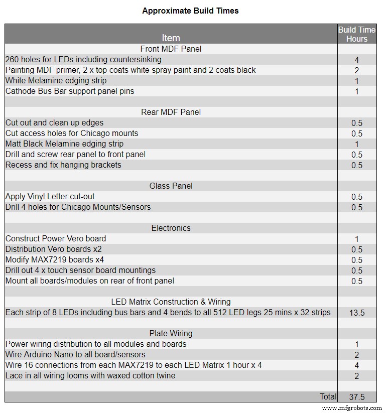
Tabelle 1 zeigt die sehr ungefähren Bauzeiten für diese Uhr und hängt von Ihrem Können und auch von Spezialwerkzeugen/Arbeitsplatz ab, die Sie zur Hand haben.
Sie können dieser Liste ganz einfach weitere 40 Stunden Prototyping- und Programmierzeit hinzufügen.
Schritt 14:Konstruktion Vinyl-Aufkleber
Vinyl-Aufkleber
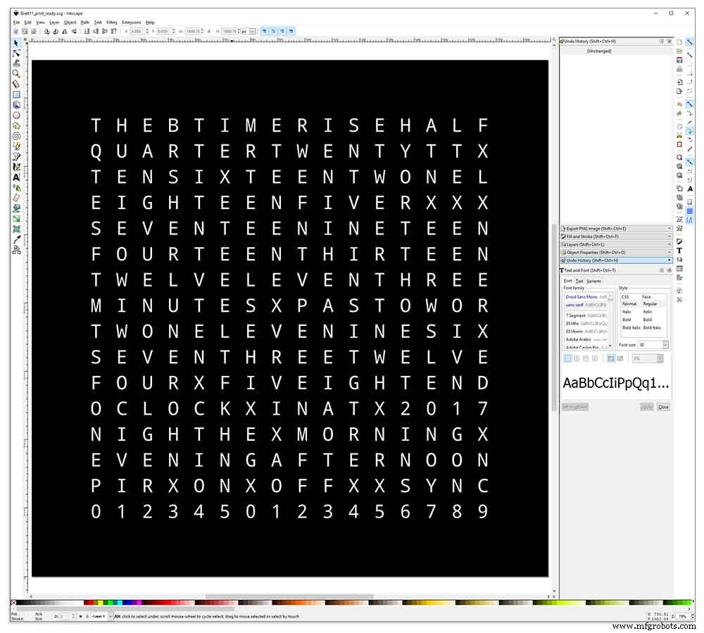
Der Vinyl-Aufkleber wurde in Inkscape entworfen.
Inkscape ist eine professionelle Vektorgrafiksoftware, die auf Windows, Mac OS X und GNU/Linux läuft. Es wird von Designprofis und Hobbyisten weltweit zum Erstellen einer Vielzahl von Grafiken wie Illustrationen, Symbolen, Logos, Diagrammen, Karten und Webgrafiken verwendet.
Inkscape verwendet den offenen W3C-Standard SVG (Scalable Vector Graphics) als natives Format und ist eine kostenlose Open-Source-Software.
Ich habe das ursprüngliche Inkscape-Design von Wouter Devinck aus seinem GitHub-Repository heruntergeladen und dann in Inkscape an mein Design angepasst. Ich habe viele verschiedene Versionen an meinem Miniatur-Prototyp ausprobiert, bevor ich das endgültige Design zum Drucken geschickt habe.
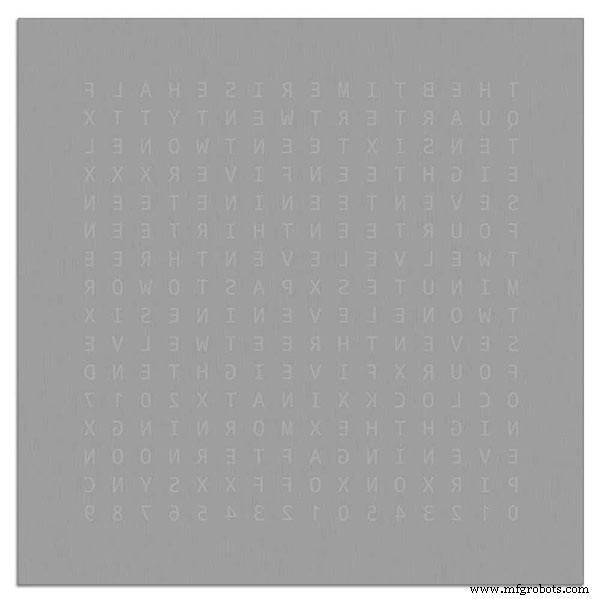
Vergessen Sie nicht, die Rückseite des Aufklebers drucken zu lassen!
Ich habe eine Firma namens Regal Signs &Graphics verwendet, die meinen Aufkleber in schwarzem Vinyl, umgekehrt geschnitten, aussortierte Schrift und mit einem Applikationsband geliefert hat, alles für etwa 27 £ inkl. MwSt.
Obwohl sie ziemlich lokal für mich sind, habe ich etwas mehr bezahlt und meinen Aufkleber in einer schönen sicheren Papprolle geliefert bekommen.
Ich hatte ein paar Probleme, das Design in das richtige Format für ihre Maschine zu bringen, aber am Ende habe ich es von Illustrator im EPS-Format gesendet. Die sehr hilfsbereiten Leute von Regal Signs haben es auf die richtige Größe für mich verkleinert. Meine Inkscape-Datei kann heruntergeladen werden hier VINYL-AUFKLEBER.
Der Vinyl-Aufkleber kam von Regal Signs, wobei die Buchstaben aussortiert wurden, so dass ich viel Zeit gespart habe. Der Aufkleber wird mit einem Plastikband über der Vorderseite (Glas) und einem Bewerbungspapier auf der Rückseite geliefert. Normalerweise ziehen Sie das seitliche Klebeband ab, bringen den Aufkleber an und entfernen dann das Anwendungspapier. Ich beschloss, das Bewerbungspapier zu belassen, da es als Diffusor für die LEDs fungierte. Da ich das Bewerbungspapier aufgelassen habe, habe ich das überschüssige Papier um den Aufkleber vor dem Auftragen abgeschnitten.
Das Anbringen des Aufklebers war relativ einfach. Stellen Sie sicher, dass Sie sich ein paar YouTube-Videos zur Vinyl-Aufkleberanwendung auf Glas ansehen, bevor Sie es selbst ausprobieren.
Glas

Die Uhr verwendet 4 mm Floatglas und wurde auf genau 500 mm x 500 mm zugeschnitten. Da die Kanten freigelegt sind, wurden auch die Kanten poliert. Dies wurde alles von meinen lokalen Glasern für 20 £ gemacht.
Dann wurden mit einem 5 mm Glasbohrer 5 mm Löcher in die Glasplatte gebohrt. Schauen Sie sich YouTube-Videos zum Bohren von Löchern in Glas an.
Ich habe das Glas zuerst mit Aceton gereinigt und darauf geachtet, dass es staubfrei ist (sehr wichtig). Ich zog dann einige Plastikhandschuhe an, um sicherzustellen, dass ich keine Fingerabdrücke auf dem Aufkleber hatte.
Ich habe das Glas mit einer stark verdünnten Seifen-Wasser-Mischung besprüht und dann ganz langsam die Plastikfolie vom Aufkleber abgezogen, um die Vorderseite freizugeben.
Es ist wichtig, die Folie langsam und in einem sehr spitzen Winkel zurückzuziehen, damit die Buchstaben auf dem Aufkleber mit dem Transferpapier verbunden bleiben. Sobald der Aufkleber vollständig freigelegt ist, tragen Sie ihn auf die nasse Glasoberfläche auf.
Mit der Wasser-Seifen-Mischung können Sie den Aufkleber an die richtige Stelle auf dem Glas verschieben. Verwenden Sie als nächstes eine Kreditkarte und arbeiten Sie von der Mitte des Aufklebers weg, um alle Luftblasen zu entfernen. Lassen Sie den Aufkleber über Nacht trocknen und schneiden Sie dann von der Rückseite des Aufklebers das Vinyl über den 4 Befestigungslöchern im Glas ab.
Brett11_print_ready.svg
Schritt 15:Bauhauptplatinen Teil 1
Hauptplatinen
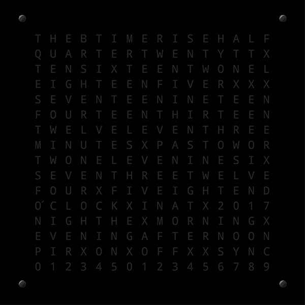
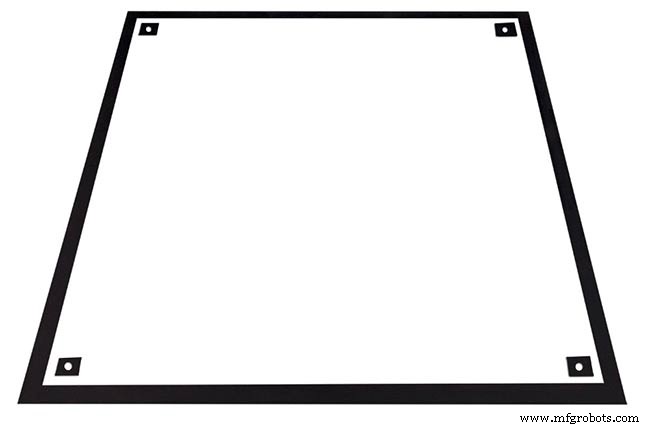
Die Hauptplatine der Uhr besteht aus 2 Platten 14mm MDF. Das hintere Blatt ist an allen Seiten außer der Oberseite 10 mm kleiner als das obere Blatt. Die Oberseite hat weiße Kanten, während die Rückseite schwarze Kanten hat. An der Wand betrachtet erscheint die Uhr dann als 14 mm tief.
Die Hauptplatine der Uhr besteht aus 2 Platten 14mm MDF. Das hintere Blatt ist an allen Seiten außer der Oberseite 10 mm kleiner als das obere Blatt. Die Oberseite hat weiße Kanten, während die Rückseite schwarze Kanten hat. An der Wand betrachtet erscheint die Uhr dann als 14 mm tief.
Bei der originalen Wouter Devinck Clock &der "katalanischen" Pijuana-Version wird eine einzelne 18 mm dicke MDF-Platte verwendet, wobei die Rückseite herausgeführt ist, um Platz für die Leiterplatte und die Komponenten zu schaffen. Durch die Verwendung von 2 MDF-Platten kann die Rückwand einfach mit einer Stichsäge ausgeschnitten werden, anstatt zeitaufwendig und staubig zu fräsen. Die obere Platte ist 503 mm x 503 mm groß, um eine Überlappung von 1,5 mm um das Glas herum zu ergeben. Dadurch wird das Glas ein wenig vor Stößen geschützt.
Die Rückwand wird mit einer Stichsäge ausgeschnitten und bietet 14 mm Platz für die Komponenten.
Die tiefste Leiterplatte inklusive Komponenten sind die MAX 7219 Module mit einer Tiefe von 10 mm. Nach Fertigstellung wird das Rückbrett mit dem Vorderbrett verklebt oder verschraubt.
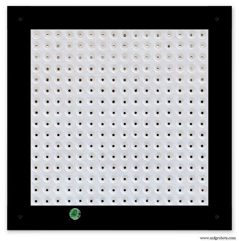
Frontboard-Konstruktion
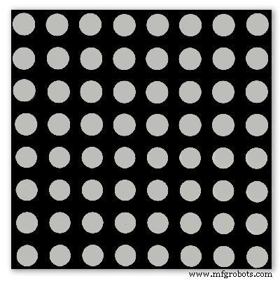
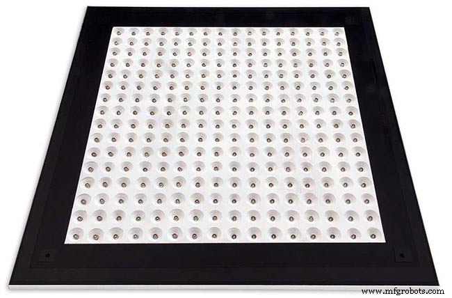
Die Frontplatine hält die 256 LEDs, die durch 6,5-mm-Löcher und breitere 18-mm-Senklöcher leuchten, um einzelne Buchstaben und Zahlen auf dem Display zu beleuchten.
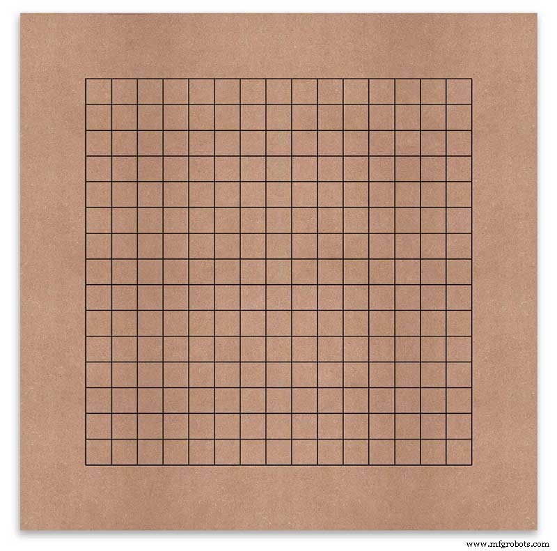
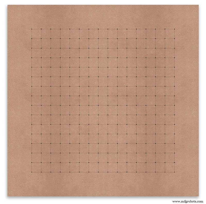
Die Platine ist markiert, um die Bohrposition in der Mitte jedes Anzeigezeichens anzuzeigen. Mit einem 500-mm-Display habe ich meine Vinylfolie gemessen und die Zeichen sind 25 mm auseinander, beginnend 62,5 mm von den Kanten. Ich habe diese Linien auf das MDF gezeichnet, wobei die Schnittpunkte die Bohrpunkte sind.
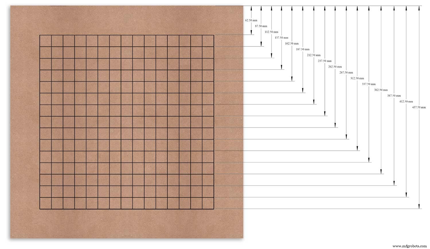
Ich habe die obere Kante als Bezugspunkt verwendet, den ich gemessen und jede Reihe von diesem Punkt aus markiert habe.
Dies wurde für die vertikale Spalte wiederholt, wobei die linke Kante als Bezugspunkt verwendet wurde.
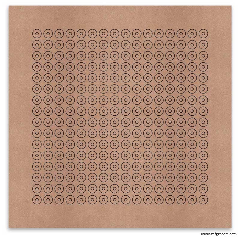
Die Schnittpunkte des Rasters bilden den Mittelpunkt für die 6-mm-LED-Montagelöcher und die 18-mm-Senklöcher.
Using an automatic centre punch ( use a nail or screw if you don't have one) I punched the 256 intersection points of the grid.
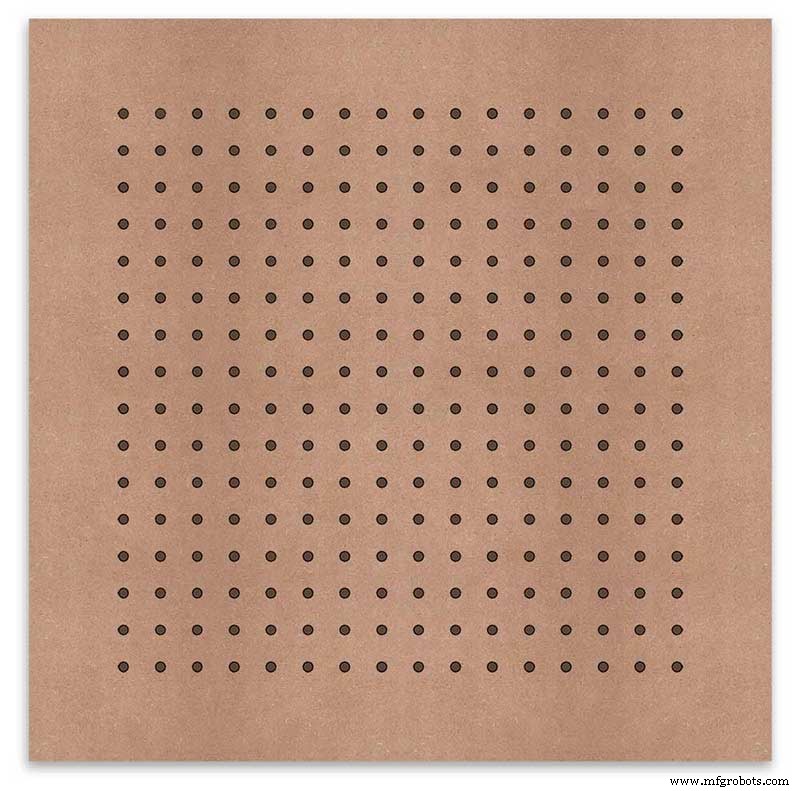
Using a drill bit to suite your LEDs (6mm in my case) and using the punched holes as a guide for the drill bit drill out all 256 LED mounting holes.
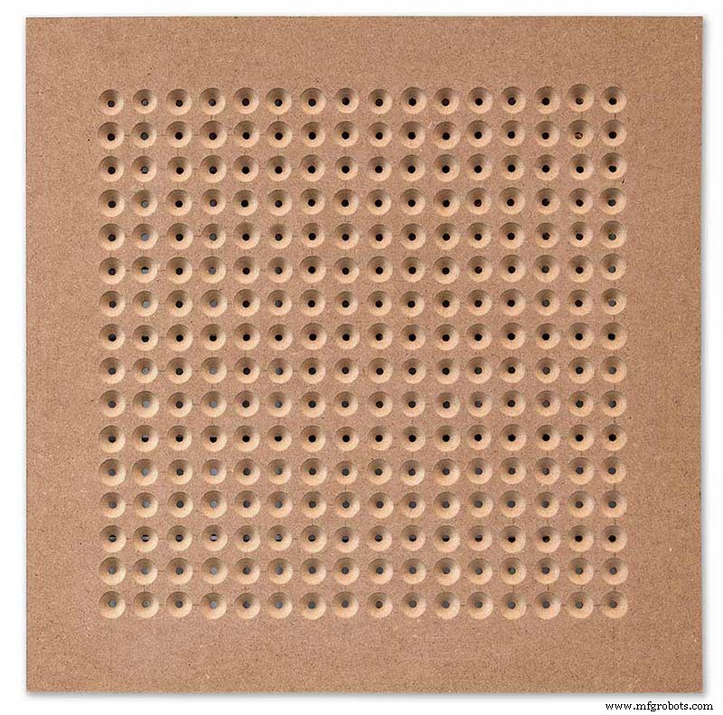
The next task is to drill the 256 18mm countersunk holes using a 20mm countersinking bit.
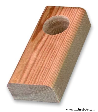
To keep the countersunk holes at a uniform depth and width I built a countersinking jig using an off cut of wood. To make the jig a hole is drilled in the wood off cut to just fit the silver rotating bezel of my drill chuck. Using a test piece of MDF the countersinking bit is then moved in and out of the chuck until a countersunk hole of the correct diameter is made when drilling through the hole upto the chuck in the off cut of wood. Once the correct distance is found the chuck is tightened and the main board is drilled 256 times by centring the hole in the wood over the existing 6mm holes then drilling down until the chuck bezel hits the hole in the countersinking jig.
Completed front board with 256 countersunk holes and 6mm holes for the LEDs.
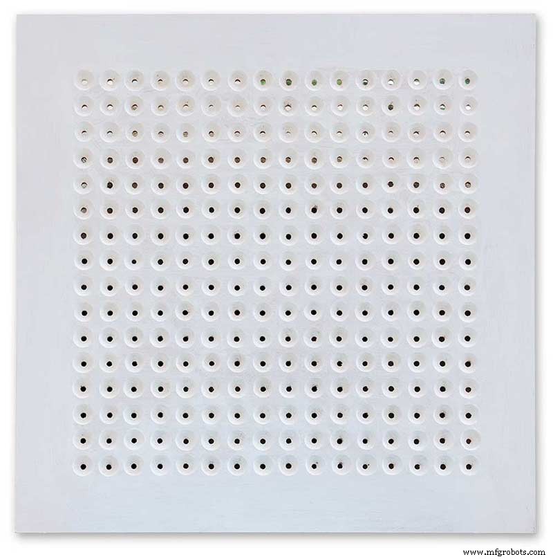
The board is then rubbed down and primed using MDF primer and painted white so the countersunk holes reflect the light from the LEDs.
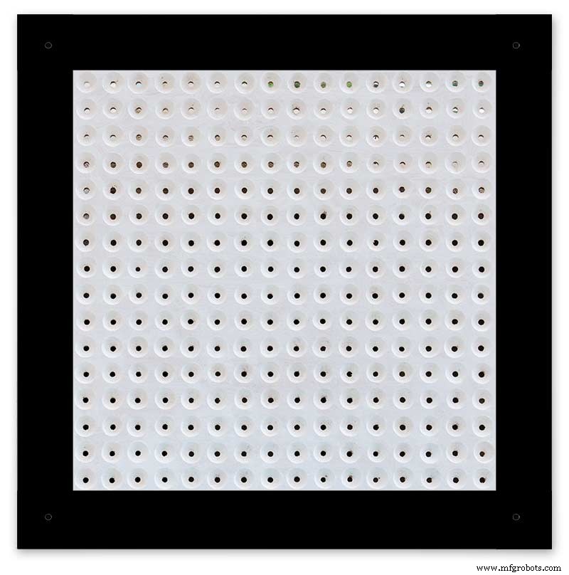
A black edge is painted around the outside edge to hide the board as the glass is 1mm shorter all round. This setback also helps the glass disappear from view on the final clock.
Four 5mm holes are then drilled in the corners to take the Chicago Fasteners. The Chicago Fasteners hold the glass in place, hold the touch sensors and provide a touch sensitive pad on top of the glass. The fasteners have 3mm shafts and will have a small bit of rubber tape wrapped around the shafts to protect the glass.
Turn the board over and drill a rebate with a forstner bit to take the four touch sensors. This hole will be offset from the hole drilled in the previous step.
Wall Mounts
The clock is fixed to the wall by two metal picture hanging mounts.
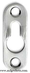
These are recessed into the frame so the highest point of the bracket is level with the frame.
Two 2" countersunk No6 screws sit in these bracket and hold the clock to the wall with a bit of tension so the dust seal is compressed.
Step 16:Construction Touch Sensor Mounting
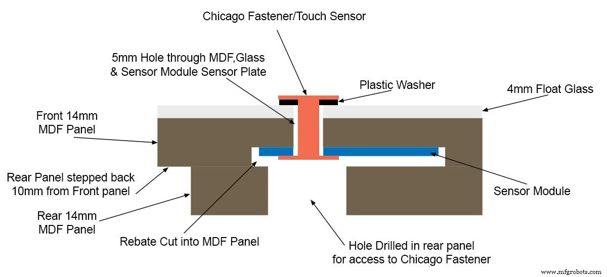
The touch sensor modules are fixed to the front panel using the Chicago Fastener bolts. The Chicago Fastener bolts then act as touch sensors.
A 5mm hole is drilled through the sensor pad on the module to allow the Chicago Fastener bolt to pass through.
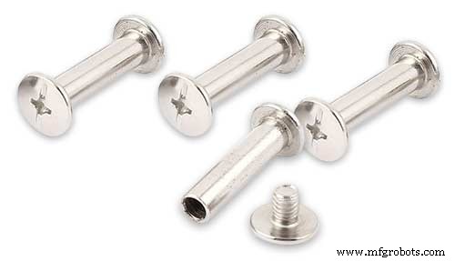
The sensor pad is insulated by the MDF panel and a plastic washer.
The touch pad on the sensor module has a 5mm mounting hole drill through the sensor.

Touch sensors in rebates behind rear panel. Holes drilled into rear panel allows access to the Chicago Fasteners that hold the sensors/glass front in place.
Clock front panel with four Chicago Fastener tops acting as touch plates.
Step 17:Electronic Components &Modules
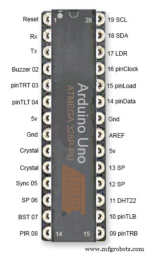
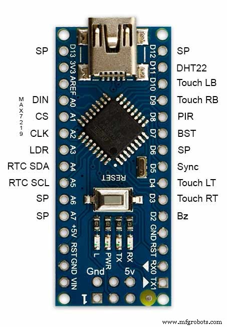
ATmega328 pin connections in case you want to prototype the circuit on an Arduino Uno. Note BST pin 07 is not used.
Pin label numbers refer to Arduino IDE numbers.
LEDs
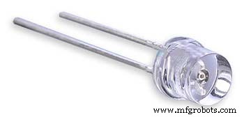
Make sure you purchase your LEDs from a good source. These LEDs will be on for many hours a day. I have has problems with LEDs failing after a few weeks use.
My LEDs Specs
5mm White Flat Top LEDs offering a pure and consistent colour with a wide angle ultra bright light output.
Colour :White
Quantity :256
Lenses Type :Round Flat Top
Crystal ClearBrightness :13000mcdForward
Voltage :3.2v - 3.8v
Forward Current :20mA (typical), 30mA (Max)
Viewing Angle :120 degrees
DHT22 Temperature &Humidity Sensor
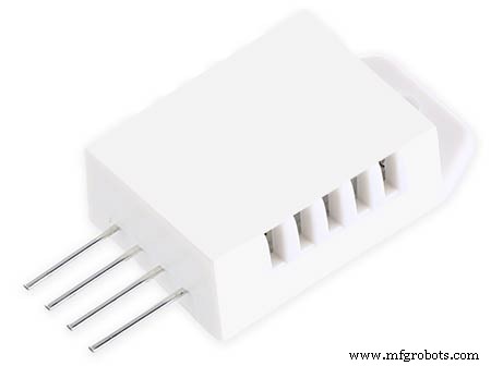
The DHT22 is a basic, low-cost digital temperature and humidity sensor. It uses a capacitive humidity sensor and a thermistor to measure the surrounding air, and sends out a digital signal on the data pin.
You can only get new data from it once every 2 seconds, so sensor readings can be up to 2 seconds old.
Simply connect the first pin on the left to 3-5V power, the second pin to your data input pin and the right most pin to ground.
To prevent the temperature of the inside clock case being measured the top and left side vent of the DH22 are covered over with tape. This also stops dust being drawn into the clock case.
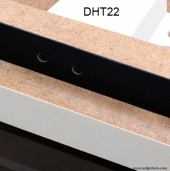
The DHT22 is mounted with its right open side mounted tight against the lower rear cover.Two small holes are drilled in the lower edge of the rear MDF board to allow air from the room to circulate around the sensor.
Arduino NANO
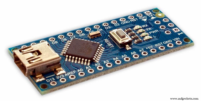
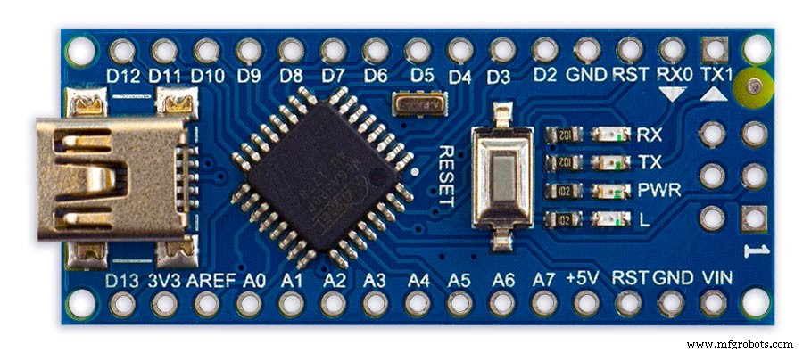
PowerThe Arduino Nano can be powered via the Mini-B USB connection, 6-20V unregulated external power supply (pin 30), or 5V regulated external power supply (pin 27). The power source is automatically selected to the highest voltage source.
Memory
The ATmega328 has 32 KB, (also with 2 KB used for the bootloader.
The ATmega328 has 2 KB of SRAM and 1 KB of EEPROM.
Input and Output
Each of the 14 digital pins on the Nano can be used as an input or output, using pinMode(), digitalWrite(), and digitalRead() functions. They operate at 5 volts. Each pin can provide or receive a maximum of 40 mA and has an internal pull-up resistor (disconnected by default) of 20-50 kOhms. In addition, some pins have specialized functions:Serial:0 (RX) and 1 (TX). Used to receive (RX) and transmit (TX) TTL serial data. These pins are connected to the corresponding pins of the FTDI USB-to-TTL Serial chip.
External Interrupts:2 and 3.
These pins can be configured to trigger an interrupt on a low value, a rising or falling edge, or a change in value. See the attachInterrupt() function for details.
PWM:3, 5, 6, 9, 10, and 11. Provide 8-bit PWM output with the analogWrite() function.
SPI:10 (SS), 11 (MOSI), 12 (MISO), 13 (SCK). These pins support SPI communication, which, although provided by the underlying hardware, is not currently included in the Arduino language.
LED:13. There is a built-in LED connected to digital pin 13. When the pin is HIGH value, the LED is on, when the pin is LOW, it's off.
The Nano has 8 analog inputs, each of which provide 10 bits of resolution (i.e. 1024 different values). By default they measure from ground to 5 volts, though is it possible to change the upper end of their range using the analogReference() function. Analog pins 6 and 7 cannot be used as digital pins. Additionally, some pins have specialized functionality:I2C:4 (SDA) and 5 (SCL). Support I2C (TWI) communication using the Wire library (documentation on the Wiring website).
There are a couple of other pins on the board:AREF. Reference voltage for the analog inputs. Used with analogReference(). Reset. Bring this line LOW to reset the microcontroller. Typically used to add a reset button to shields which block the one on the board.
Communication The Arduino Nano has a number of facilities for communicating with a computer, another Arduino, or other microcontrollers. The ATmega328 provide UART TTL (5V) serial communication, which is available on digital pins 0 (RX) and 1 (TX). An FTDI FT232RL on the board channels this serial communication over USB and the FTDI drivers (included with the Arduino software) provide a virtual com port to software on the computer. The Arduino software includes a serial monitor which allows simple textual data to be sent to and from the Arduino board. The RX and TX LEDs on the board will flash when data is being transmitted via the FTDI chip and USB connection to the computer (but not for serial communication on pins 0 and 1). A SoftwareSerial library allows for serial communication on any of the Nano's digital pins. The ATmega328 also support I2C (TWI) and SPI communication. The Arduino software includes a Wire library to simplify use of the I2C bus. To use the SPI communication, please see ATmega328 datasheet.
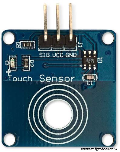
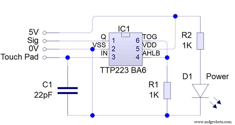
TTP223 Touch Sensor Module
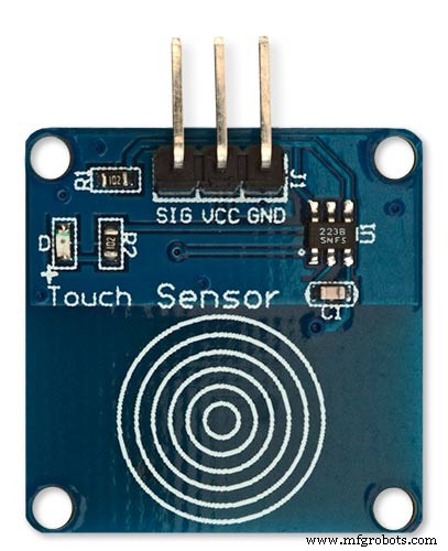
The touch Sensor Module is bolted to the front panel using the glass mounting bolts. The bolt goes through a 5mm hole drilled in the middle of the sensor.Note the mounting bolt is touched to trigger the sensor but is insulated from the sensor itself through plastic washers. Four of these modules are used in the clock one mounted on each corner of the glass.
Note the LEDs are not required and are removed from the modules (just break them off) to save power.
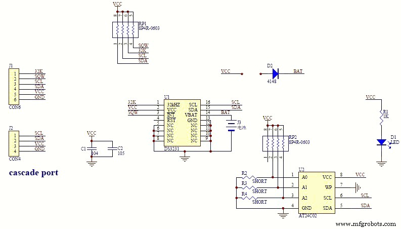
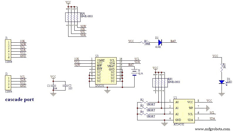
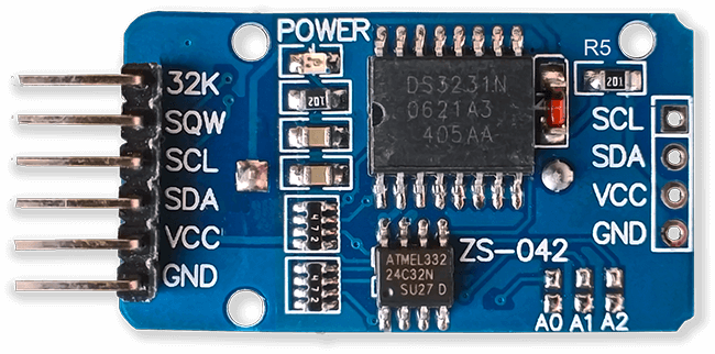
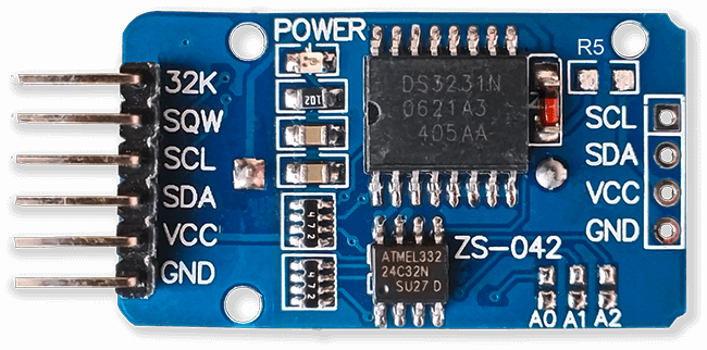
DS3231 AT24C32 I2C Precision Real Time Clock Module
My clock uses a DS3231 AT24C32 I2C Precision Real Time Clock Module.The module comes supplied with a Lithium-Ion rechargeable battery see diagram below. I use a non rechargeable battery so have removed resistor R5 from the module.
MAX7219 Display Module
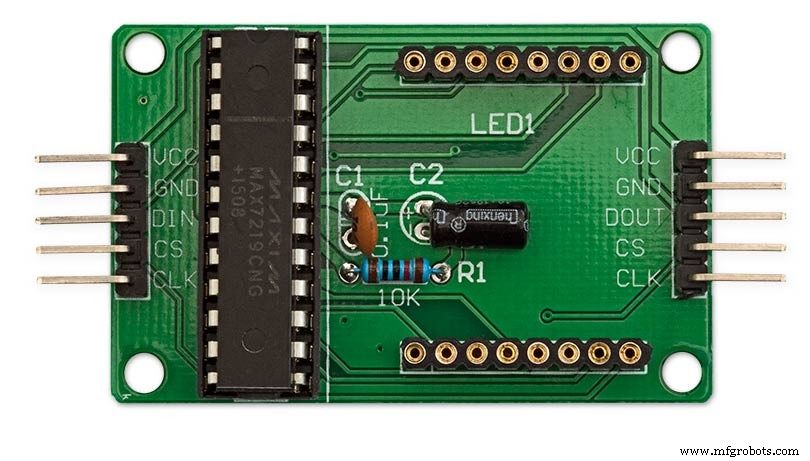
MAX7219 LED current limiting
The max current through the LEDs is set by a single resistor R1 on the module. The value of resistor can be found from the table below.
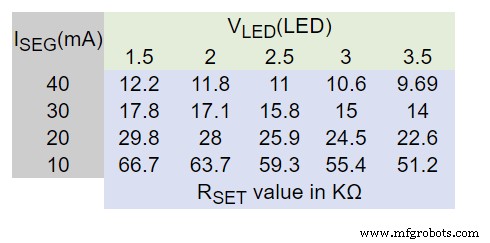
The module comes with a 10K resistor preinstalled but this can be removed and a resister to match your LEDs current added in its place. My LEDs Forward Voltage is 3.2v - 3.8v @ 20mA. They can handle 30mA max but for long LED life 20mA is best. I have used 22KΩ resistors which will limit the current to around 20mA when the light levels are at their peek.
See setting automatic brightness levels.
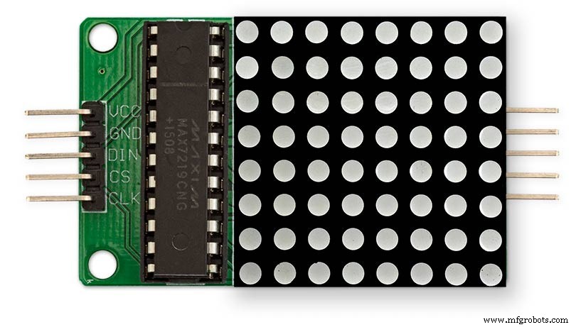
1088AS LED Dot Matrix display

1088AS LED Dot Matrix display view of lower edge Pins 1 to 8 left to right.
This is used for prototyping and is not required in the final project.
LDR
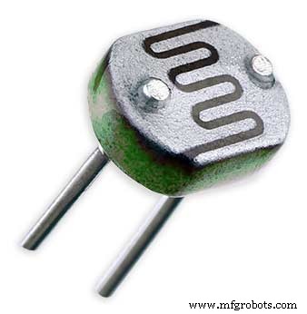
An LDR is used to sense the ambient light levels. The LDR is around 500Ω in bright light and 10MΩ in the dark.
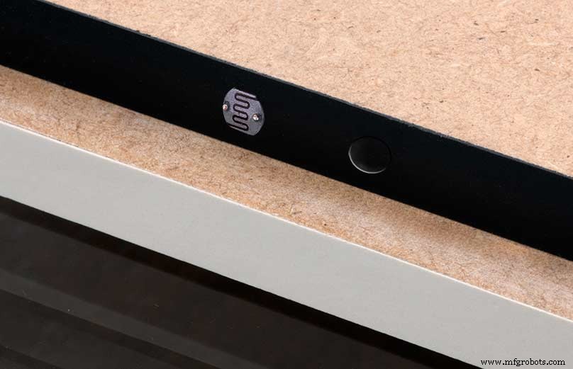
The LDR is positioned underneath the clock on the rear MDF panel.
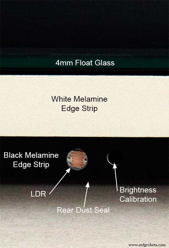
Next to the LDR is a hole to give access to the trimmer resister to calibrate the LED brightness control.
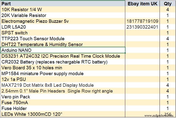
Component List
Step 18 Dust Seals
To prevent ingress of dust two dust seals are fitted.
On the rear MDF board a 2mm soft foam rubber dust seal is fitted. When the clock is hung on its hanging hooks the seal is under pressureand seals the back of the clock to the wall.
The seal is self adhesive and is fitted with a 5mm gap to the edge of the rear MDF board.
On top of the front board to prevent dust getting under the glass a strip of self amalgamating rubber is fitted 5mm from the board edge.
To prevent the glass from cracking when the Chicago bolts are tightened 4 small square of rubber are also fitted around the holes in the glass.
I punched holes for the Chicago Bolts in the rubber with a leather punch.
Step 19:Schematic
Nano Connections
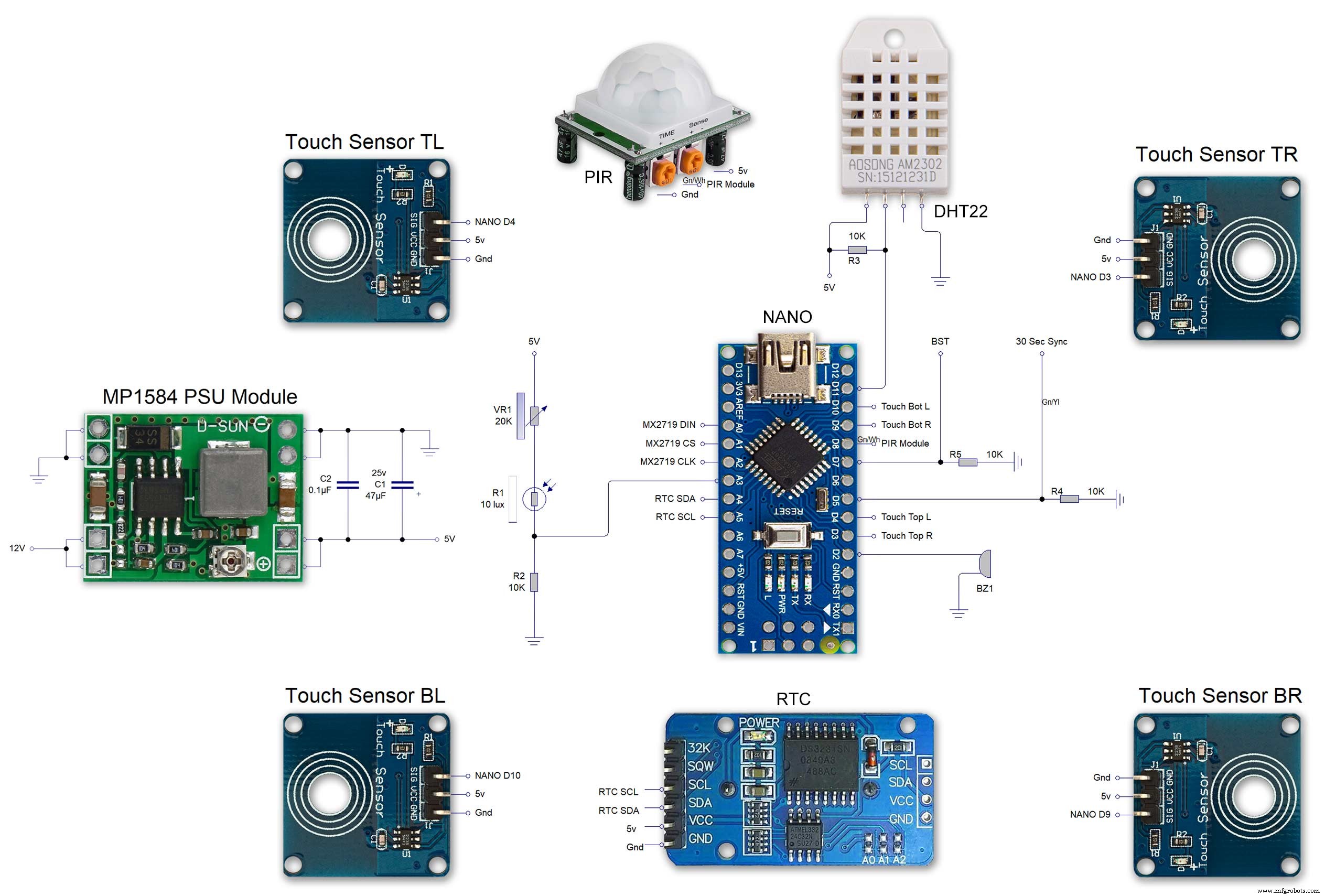
The connections to the Arduino Nano. Download the full size file from the hardware section
MAX2719 connections


The 4 MAX7219 modules and the connected LED matrixes.
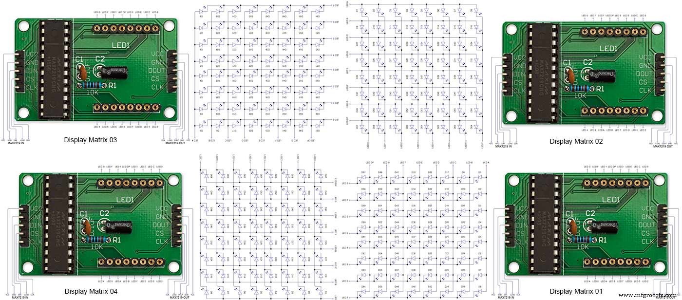
Note the LED display matrixes are rotated anti-clockwise 90 degrees from each other starting from display matrix 01.Display Matrix 01 input is wired to the Arduino CLK, DIN and LOAD the output is taken to the input of Display matrix 02 etc etc.
Step 20:Wiring Building the LED Matrixes
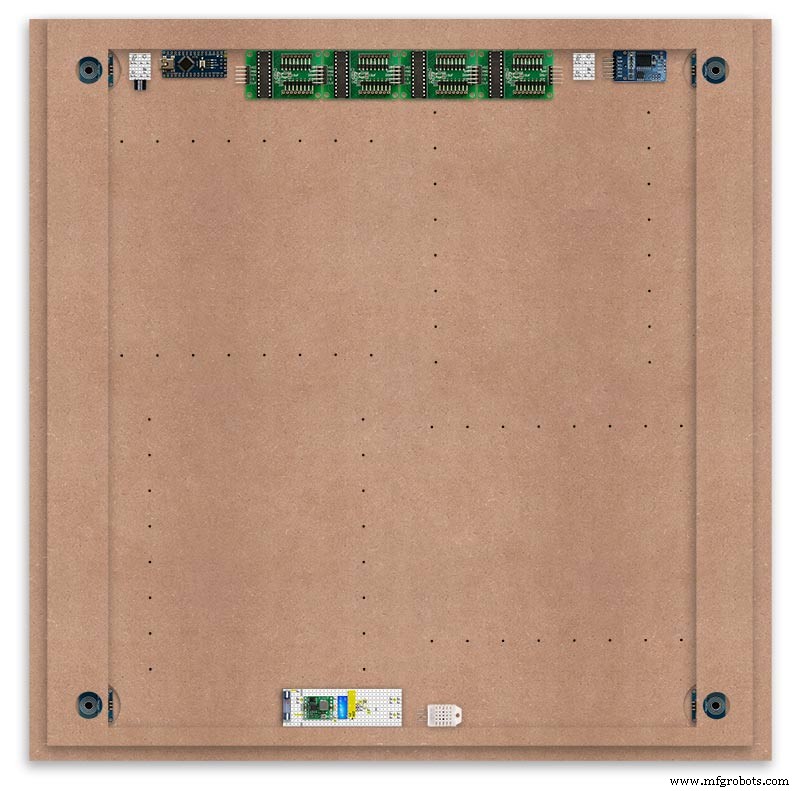
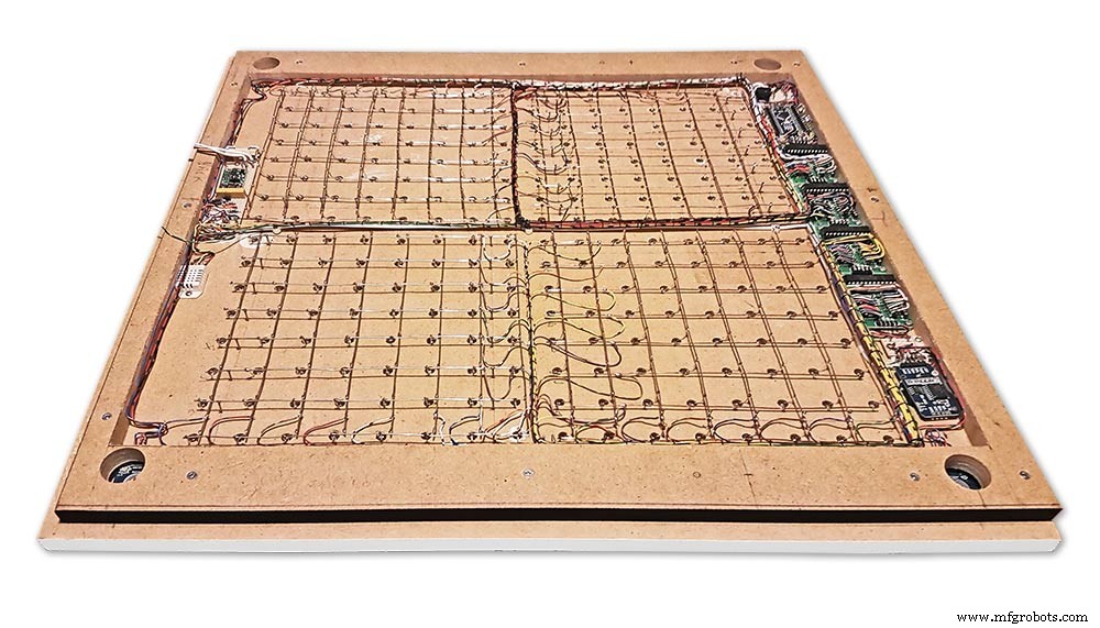
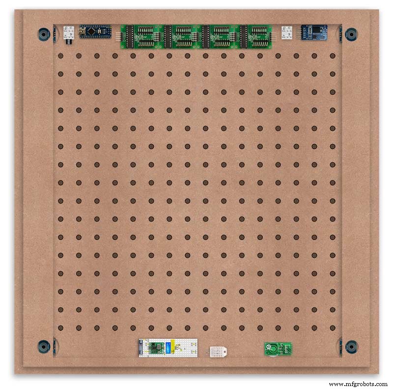
Module Locations

The module locations are shown above. The four sensors are located in the recesses on the main board behind the rear board. Holes are cut into the rear board to allow access for fit the Chicago Bolts/Sensor pads.
The four MAX7219 Display Modules are soldered together and are mounted in the centre top of the board. This keeps the data links between the boards as short as possible.
The Arduino Nano is mounted on the left of the MAX7219 Display Modules and the RTC on the right. The RTC battery holder on the base of the RTC module is recessed into the main board.
The Vero board containing the power module is located on the lower part of the board. There are two power distribution boards mounted on the top of the clock. The main 5v 2A feed cable is taken to both of these boards and power is then distributed to the other boards from these points.
The MAX7219 board power is fed from the left board and daisy chained through each board then taken out the forth board to ensure they are fed with 0v and 5v from both ends.
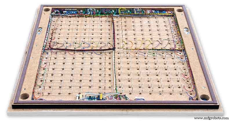
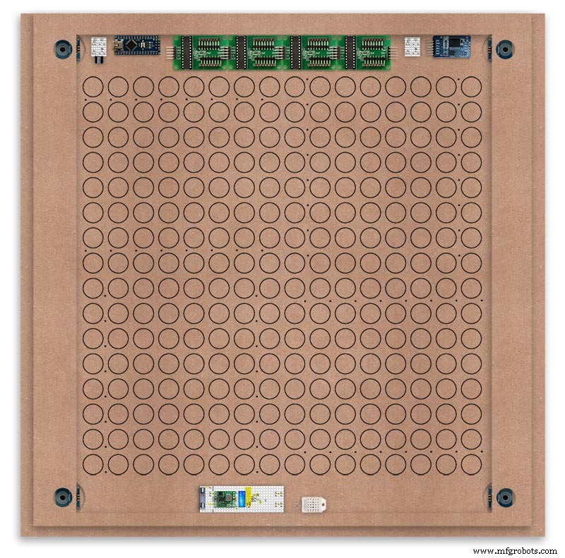
The LED locations are shown. The LED matrixes each contain 64 LEDs and are labelled 1 to 4.
These correspond to the 4 MAX 7219 modules mounted above numbered 1 to 4 left to right. Note this is the rear of the clock so number will be revearsed.
The LED Matrixes are built up off 2 types of BUS Bars per module. A Cathode Bus at 10mm high and an Anode BUS bar at 2mm high.
There are 8 Cathode and 8 Anode BUS Bars per module. Each module has 16 x 15mm panel pins hammered into the board in the position shown to support the 10mm high Cathode BUS.
The 15mm panel pins are hammered in 5mm (I used a 10mm piece of metal bar as a gauge) leaving 10mm as Cathode BUS bar support pins.
As shown above the pins correspond with the thick parts of the board not the recess for the LEDs on the front of the board. Note the LED recess is on the front of the board and can't be seen from the back.

0.9mm copper wire is then soldered to each pair of pins to form the Cathode BUS Bar.
Note the rotation of each module and also the modules are in reverse as it is the back of the board the LEDs are connected to.
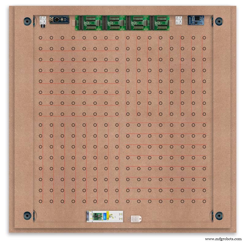
The Anode BUS Bars are shown below in Red and are supported off each LED Anode about 2mm off the MDF board. No Pins required.

Both Cathode &Anode BUS Bar locations are shown below.
Each LED is connected to an Anode and Cathode of the Matrix.
Step 21:Wiring the LEDs
LEDs
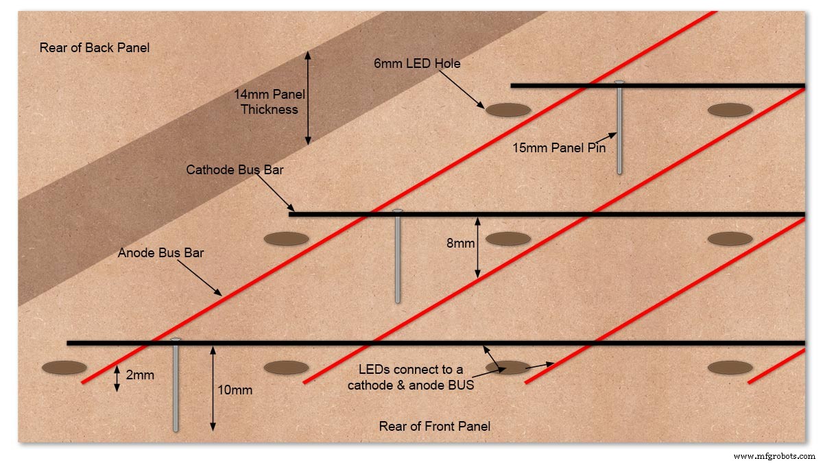
Diagram showing Bus Bar layout with panel pins supporting the Cathode Bus. This module has horizontal Cathode and vertical Anode Bus Bars.
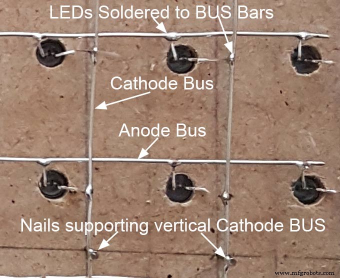
Close up section of Module wiring.The Cathode BUS Bars run vertically and the Anode BUS Bars run horizontally on this module. The Anode &Cathode BUS Bars have an 8mm vertical separation.
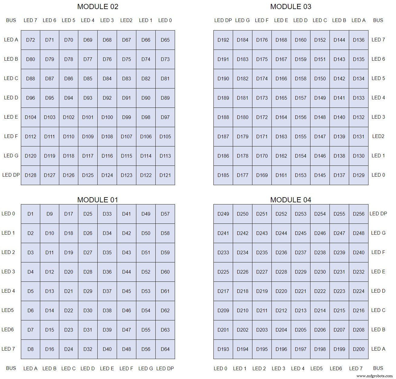
The LEDs are connected to the matrixes and MAX7219 modules from the rear. The LED positions will be reversed and of course rotated 90° relative to the next module. This makes it very complicated connecting the correct LEDs and Bus bars from the rear of the board. The table below shows the LED positions in the blue boxes with the BUS Bar matrix position in black around the outside as they appear from the back of the front MDF board.
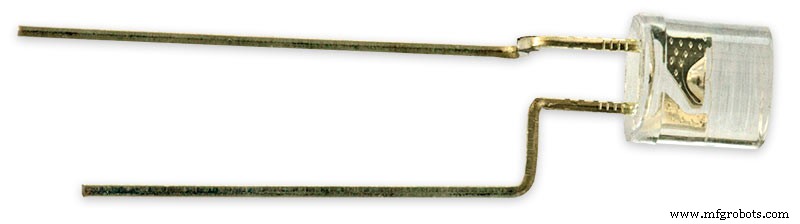
The LEDs are bent in a jig to keep the position in the display constant and to speed up construction. Each LED has four bends two on each leg that's 1024 in total! The Cathode leg is bent 90° from the Anode.
The Matrix grids are wired to the corresponding pins on the MAX7219 modules according to the layout table.
There are 16 wires to each module.
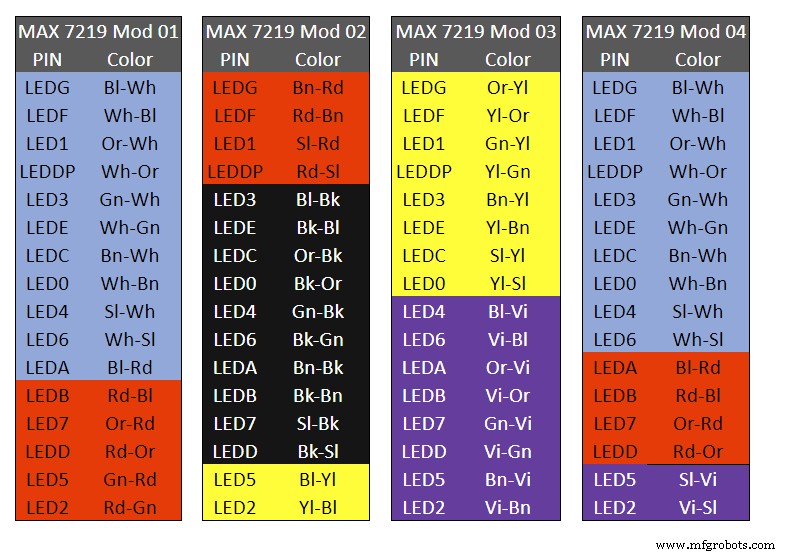
Table 1 Module LED Matrix Wiring Colour Code is shown above.
Each Module has 16 wires connecting it to the LED Matrixes. I have used 50pr 0.5mm cable so the last 14pr colours are duplicated. On Mod 4 I went out of order and missed out the Sl/Vi at the start so have put it in at the end.
Step 22:Wiring Modifying the MAX7219 Modules
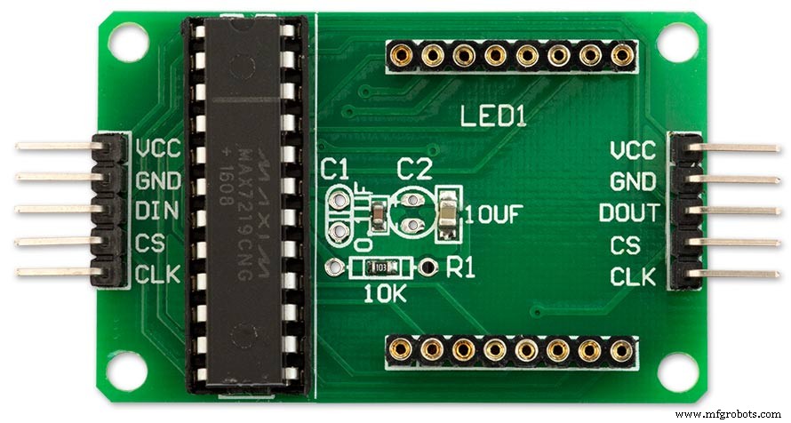
Before wires can be connected to the MAX 2917 modules they will need to be modified.
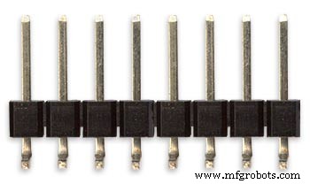
Two sets of 8 90° pin connectors will to be soldered to the lower edge of the existing LED matrix connector.

Modified MAX7219 module with 90° pin connectors soldered in place to the bottom of the old LED Matrix connectors.
Wires are taken away from these points to the LED matrix on the main MDF board as per the LED Matrix Wiring Colour Code table on the previous step.
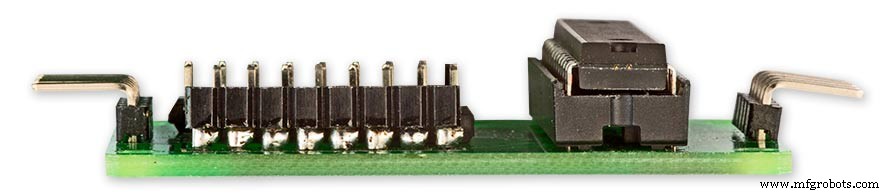
Side view showing the pins soldered to the side of the old LED Matrix connector pins just above the PCB.
Note if your MAX7219 Module does not have surface mount components the 90° pin connectors may need to be trimmed back so they don't foul R1, C1 or C2.
MAX7219 LED current limitingThe max current through the LEDs is set by a single resistor R1 on the module. The value of resistor can be found from the table below.

The module comes with a 10K resistor preinstalled but this can be removed and a resistor to match your LEDs current added in its place.
My LEDs Forward Voltage is 3.2v - 3.8v @ 20mA. They can handle 30mA max but for long LED life 20mA is best. I have used 22KΩ resistors which will limit the current to around 20mA when the light levels are at their peek.
Note this sets the max current through your LEDs actual brightness is controlled by the LDR/software/ trimmer resistor and will usually be far less than this.
Setting Automatic Brightness Levels
The clock automatically senses the ambient light and adjusts the LEDs accordingly.
When first installed the clock will need to be calibrated to the maximum light levels in its actual location.

Connect a mobile, laptop/tablet etc via a suitable cable to the mini USB port of the clock and open an app to monitor the serial port.
I use Slick USB 2 Serial Terminal on my S7 via an OTG cable and USB to mini USB cable.
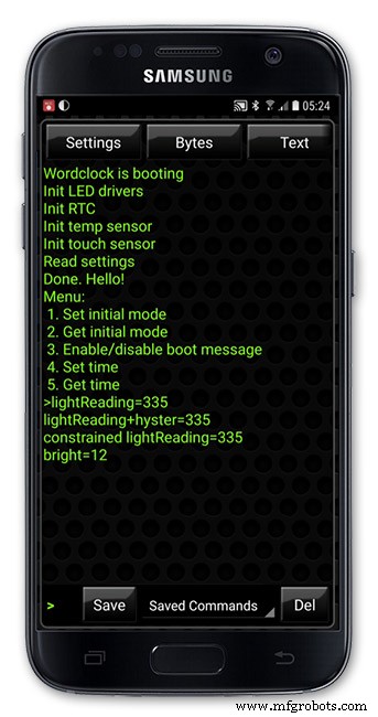
The clock will reboot and after the initial start screen you will see the following data updating down the screen.
You don't need to worry about lightReading or constrained lightReading+hyster just light reading, and bright.
With the clock in position and the ambient light at its maximum levels carefully insert a flat bladed jewellers screwdriver into the access hole just to the right of the light sensor.
Turn the screwdriver slowly until the light reading =600 (or your level set in brightness.cpp) and bright =15.
Your clock will now go to max brightness when the ambient light is at its maximum.
If you turn the screwdriver too far the light reading will go over 600 but the bright reading will not increase.
If you want the clock to be dimmer right across the range of ambient light levels adjust the light reading to a level less than 600 at max ambient light levels.
Note when bright=15 this will output the max current to the LEDs. The max current is set by R1( RSET) on the MAX7219 module and this should be chosen for your type of LED used in the display.
Step 23:Wring Mini USB Port
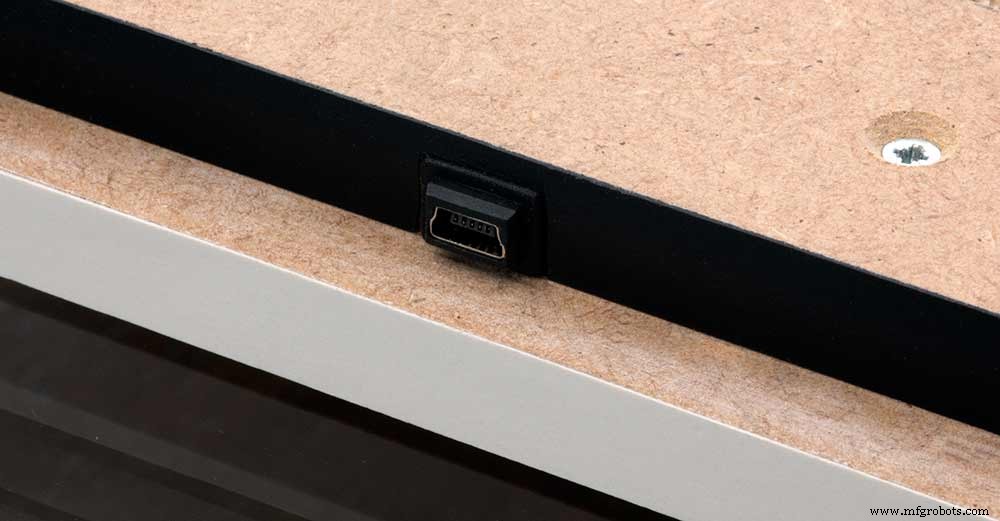
To allow adjustment/checking of light levels and programming of the clock a Mini USB socket is cut into the right hand side of the rear MDF sheet.
I have used a 25cm 90° Right angle Mini USB Male to Female Extension Cable and stripped back the insulation sleeve and shielding to expose the wires. This allows the cable to bend around the sharp angles and tight spaces of the enclosure.
Step 24:PIR Controlled Display Shutdown
This is optional as a Doppler Radar module can be fitted inside the clock instead.
See next section.
The PIR when enabled on the word clock menu (bott left PIR On, bott right PIR Off) turns on the display when movement is detected in the room.
When no movement is detected the display turns off after a set period of time. When the PIR is enabled the displays shows "PIR ON" and when disabled (display always on) it shows "PIR OFF" Note when the PIR is not enabled the display is always On.
The PIR module is fitted remote from the clock in a modified chrome light switch box. The box is cut into a plasterboard wall and also contains a switch to turn the clock off. The module itself is very small and can be mounted in a tiny enclosure if you don't want it on show. It will not work behind glass so if you wanted to mount it on the clock a hole would need to cut in the glass. This is very easy to do with a large hole cutter.
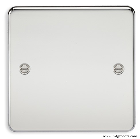
A blank chrome switch plate and back box are used to house the power switch and PIR module.
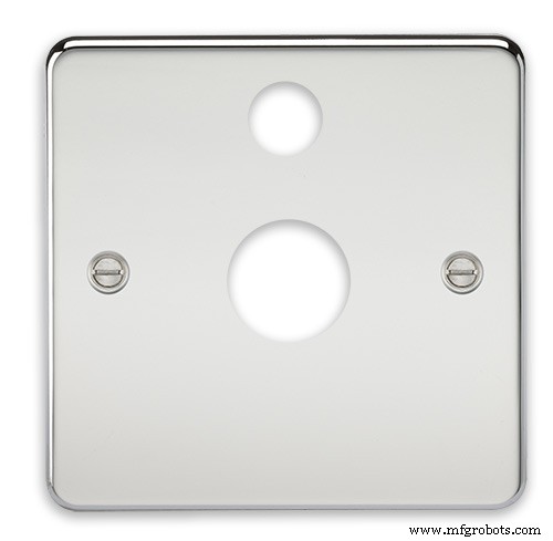
Two holes are drilled in the blank switch plate for the power switch and PIR lens.
The hole are centre punched, pilot drilled and then drilled out just big enough for a step cutter to fit through. The hole for the PIR diffuser is cut just big enough for the lens to go through with a friction fit.
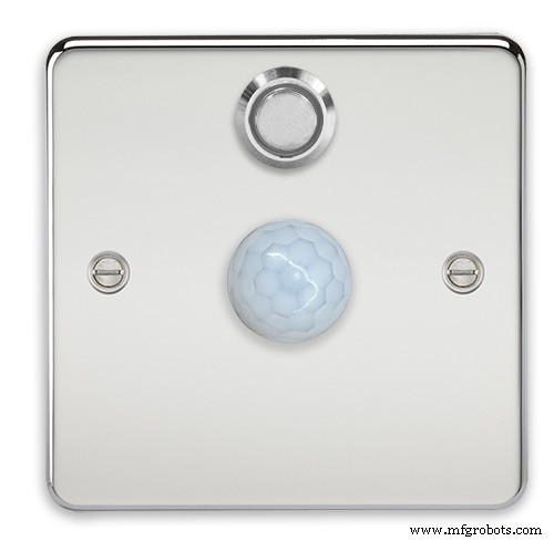
The completed switch plate.
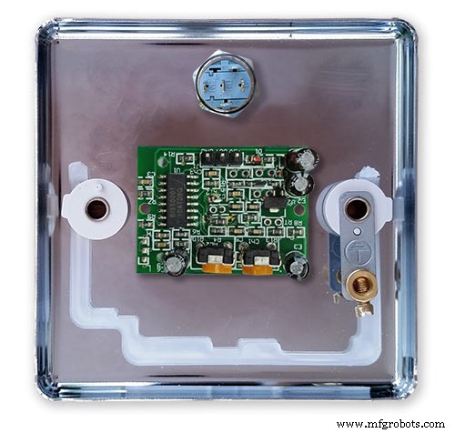
The 12 volt supply +ve is terminated on the switch with the 0v terminated on the earth screw.
12 volts is then fed back upto the clock PSU Vero board from the other side of the switch and again the earth screw. 5 volts are fed from the clock PSU Vero board to supply the PIR module.
The 5 volts and PIR sensor wire to the clock terminate on PCB header sockets. These are is plugged into the PIR Module header pins. The sync cable is terminated on a header pins and connects to the Master Clock 30 second sync cable via a single header socket.
The PIR has 2 trimmer resistors for adjusting sensitivity and also length of time the PIR &display stay activated.
PIR On/Off Control:The PIR is turned on and off in word clock mode by touching the bottom left sensor to turn the PIR on or by touching the right sensor to turn the PIR off. Note when the PIR is set to off the display stays on permanently. When you change the PIR setting the work "PIR ON" or "PIR OFF" is displayed for 5 seconds.
When initial power up the default is PIR off if you switch the PIR On straight away the display will go off as the PIR takes a minute or so to initialise before detecting movement.
Photo 6 &7 "PIR ON" or "PIR OFF" are displayed for 5 seconds when PIR setting is changed.
Step 25:Doppler Radar Control Option
Optional Doppler Radar Module can be added in place of the PIR above.
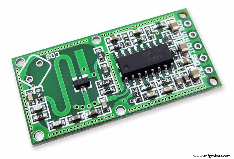
The Doppler Radar when enabled on the Word Clock menu (bott left PIR On, bott right PIR Off) turns on the display when movement is detected in the room. A check is made for motion on every quarter hour. When no movement is detected the display turns off until movement is detected again.
When the PIR is enabled the displays shows "PIR ON" and when disabled (display always on) it shows "PIR OFF" Note when the PIR is not enabled the display is always On. Unlike PIR modules the Doppler Radar module can see through glass and plastic and is fixed into the case of the clock behind the glass and PVC sticker. The module has a range of around 5m or 16' 5".
Doppler Radar Module fixed inside the case. A hole is drilled in the front panel to allow the module to monitor the room.
Front panel showing hole through to the Doppler Radar module microwave sensor.
The module is hidden from view behind the PVC sticker and glass.
Step 26:PIR/Doppler Radar On Off Control
The PIR is turned on &off in word clock mode by touching the bottom left sensor to turn the PIR on or by touching the right sensor to turn the PIR off.
Note when the PIR is set to off the display stays on permanently.

When you change the PIR setting the work "PIR ON" or "PIR OFF" is displayed for 5 seconds.
When initial power up the default is PIR off if you switch the PIR On straight away the display will go off as the PIR takes a minute or so to initialise before detecting movement.
Step 27:Setting Automatic Brightness Levels
The clock automatically senses the ambient light and adjusts the LEDs accordingly.
When first installed the clock will need to be calibrated to the maximum light levels in its actual location. Connect a mobile, laptop/tablet etc via a suitable cable to the mini USB port of the clock and open an app to monitor the serial port. I use Slick USB 2 Serial Terminal on my S7 via an OTG cable and USB to mini USB cable.

The clock will reboot and after the initial start screen you will see the following data updating down the screen.
You don't need to worry about lightReading or constrained lightReading+hyster just light reading, and bright.With the clock in position and the ambient light at its maximum levels carefully insert a flat bladed jewellers screwdriver into the access hole just to the right of the light sensor. Turn the screwdriver slowly until the light reading =600 (or your level set in brightness.cpp) and bright =15. Your clock will now go to max brightness when the ambient light is at its maximum. If you turn the screwdriver too far the light reading will go over 600 but the bright reading will not increase.
If you want the clock to be dimmer right across the range of ambient light levels adjust the light reading to a level less than 600 at max ambient light levels.
Note when bright=15 this will output the max current to the LEDs. The max current is set by R1( RSET) on the MAX7219 module and this should be chosen for your type of LED used in the display.
Step 28:Setting the Clock
The clock is set in the digital clock mode by touching the bottom left sensor.
The hour digits will now flash twice a second to indicate the clock is in time setting mode.In this mode the sensors have the following functions.
Top right - steps the hours or mins digits up
Top left- steps the hours or mins digits down
Bottom left 1sr press - enters the time setting mode selecting hours digits
Bottom left 2nd press -selects the mins digits for changing
Bottom left 3rd press -exits time setting mode and sets the time
Bottom right - resets the seconds to 00
Step 29:Synchronisation
If you have connected a 30 second master clock sync cable then the clock will jump back or forward to 30 seconds when out of time setting mode. If you don't have a Master Clock to sync to then the clock will fall back on the on board temperature compensated real time clock which in itself is a very precise quartz clock.
Just reset the seconds roughly in sync to the seconds (within 10 seconds either way) and wait for the clock to sync once out of time setting mode.
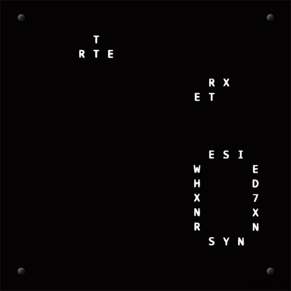
The animated loop below shows the Word Clock is running fast by several seconds. A synchronisation pulse is received from the Master Clock every 30 seconds on the minute and half minute synchronising the clock on 30 seconds.
The clock will ignore the 30 second synchronisation pulse from the Master Clock at 0 seconds. Note clock synchronisation only happens when the Word Clock is 20 seconds past and 20 seconds to a minute. In normal operation the sync pulse corrects the clock to within a fraction of a second so you will see the word "SYNC" appear with no visible correction to the seconds.
Note the synchronisation pulse is received every 30 seconds but the clock will ignore pulses at 0 seconds.
Step 30:Software &Making Changes
The software can be downloaded from the software tab and contains the following modules.
Program Files Modules
Brett_wordclock_v4_3.ino Main program, latest update includes shortened code saving 10% in size.
Thanks to srdevil for providing the updated code for this seconds display.
brightness.cpp/.h Brightness autoadjustment
character.cpp/.h Character (digit) definitions
credits.cpp/.h Ending Credits
display.cpp/.h Display &LED functions
life.cpp/.h Game of Life
serial.cpp/.h Serial port setup menu
simon.cpp/.h Simon Says game
temphum.cpp/.h Temperature &Humidity displa
tetris.cpp/.h Tetris game
time.cpp/.h Wordclock, digital clock
timeanalog.cpp/.h Analogue clock
touchbuttons.cpp/.h Touch buttons, mode switching
Third party libraries:
Chronodot.cpp/.h Chronodot library (for DS3231)
DHT.cpp/.h Temperature sensor library (for DHT22)
LedControl.cpp/.h LedControl library (for MAX7219)
stc.cpp/.h/platform.h Simple Tetris Clone library
pitches.h Note frequencies from the Arduino webpage
When you want to make changes to my code you can compare my code to the "Catalan Code" to make it easier to understand what changes you need to make. I have added //Brett to my code to highlight my changes.
Changing the code.
If like me you are not very good at coding just play around with the code to get an understanding of how it works.
I just save a different version each time I make even a tiny change. This way if I mess up I can go back a version and start again.
If you are keeping my linear seconds display update the version number on the display so you know what version you are trying out each time. This is done in the module credit.h around line 47.
It would take far too long to explain all the code but here is a very brief guide on how to change the words and when they are displayed.
The WORDS are set in time.h
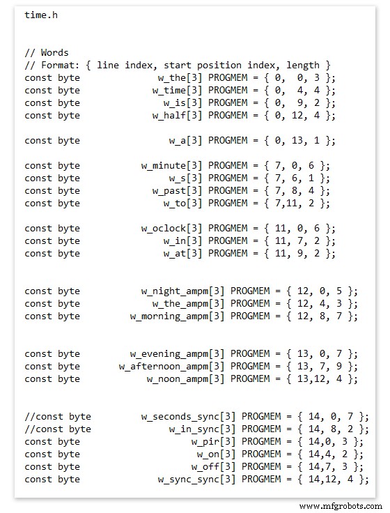
On line 52 we have
const byte w_the[3] PROGMEM ={ 0, 0, 3 };
The word "THE" is described in this line with the LED location in the curly brackets "{ 0, 0, 3 }"
This is the co-ordinate of the LEDs we are gong to light when we call "w_the"
The LED matrix numbers starts top left and start from 0 so "{ 0, 0, 3 }" is the first LED across and down the 3 just means the 3 LEDs across including this one will light. As the letters THE are in this position the word "THE" is displayed.
Similarly the word "TIME" would be lit by lighting the four LEDs here { 0, 4, 4 } or row 0, 5th LED along and light 4 LEDs (remember to count from 0).
Working you way down the page shows the position of all the words.
Controlling when words are lit
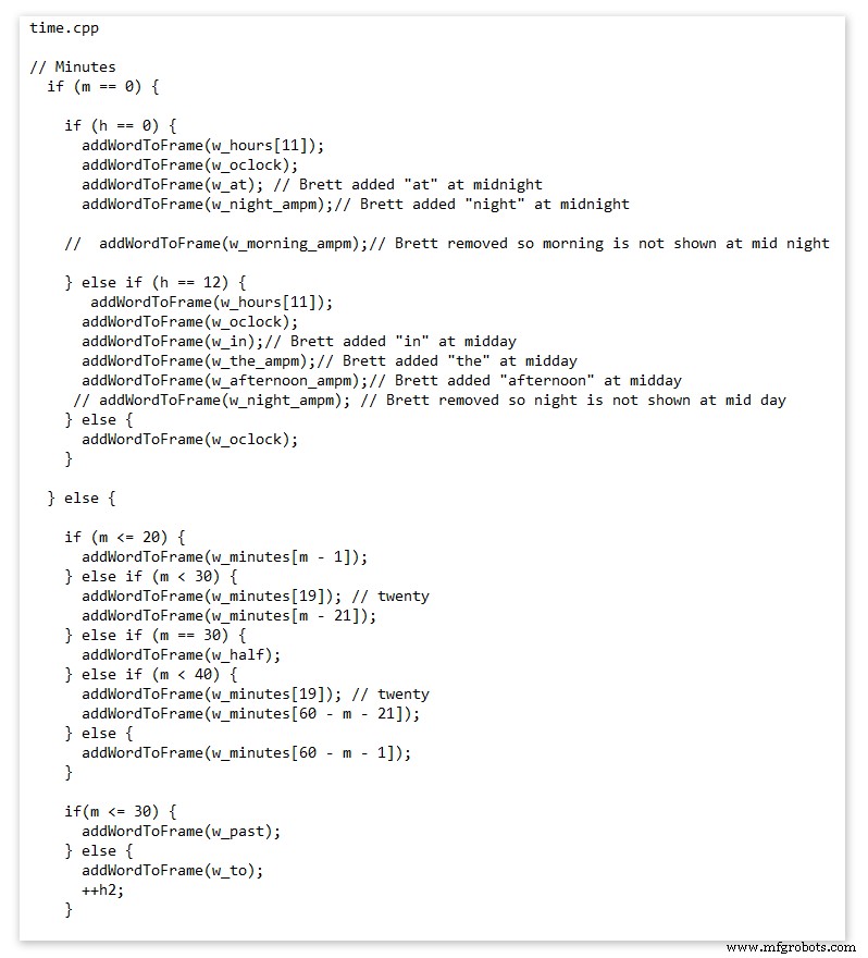
This happens in the module time.cpp
Here you just make a list of rules to tell the clock what words to light at certain times.
Pic above shows part of the code starting with line 695
At midnight we want to make the clock say "THE TIME IS TWELVE OCLOCK AT NIGHT"
Midnight is 00 00
"THE TIME IS" is always displayed from lines 687
So we add the rules if minutes are 0, then if hours are 0 show the word for hours "TWELVE" and the word "OCLOCK" the word "AT" and the word "NIGHT"
If you follow the code down all the possible time combinations are covered.
Analogue Clock Code Change - increase in time definition One of the comments sent to me by srdevil was some code changes. His comment can be seen below.
I have not had time to test the code but have included it below if you want to try it out.
" If the time is 18:00, it points up (long leg) and down (short leg). But when the time is 18:59, it still points totally down (short leg) so it looks like the time is 17:59 on a normal clock. My brother change the code so that if it is>HH:15 the small pointer moves already to the next number. As of this we also increased the resolution in the part between>HH:15 -
Code on the comments section or can be seen here http://home.btconnect.com/brettoliver1/Word_Clock/Word_Clock.htm#analogeclock
Code
- Brett_wordclock_v4_5.zip
Brett_wordclock_v4_5.zipArduino
Load into Aduino IDENo preview (download only).
Github
https://github.com/wouterdevinck/wordclockhttps://github.com/wouterdevinck/wordclockGithub
https://github.com/svcabre/wordclockhttps://github.com/svcabre/wordclockMy Word Clock on GITHUB
Schematics and code https://github.com/brettoliver/wordclockKundenspezifische Teile und Gehäuse
Vinyl Sticker Design in Inkscape (free to download) change as required brett11_print_ready_6bbpMTDyFa.svgSchaltpläne
Schemaic showing main board connections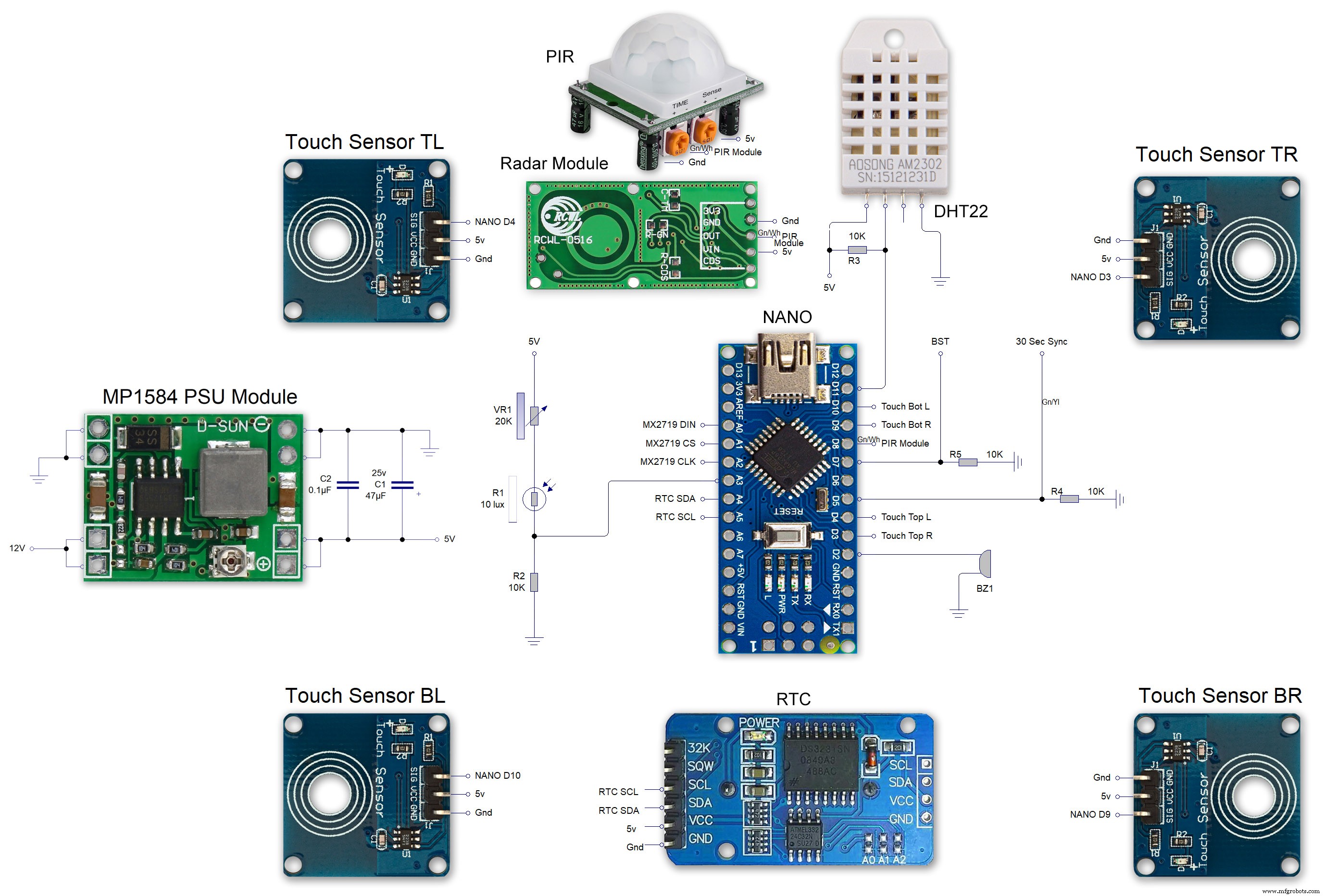 MAX7219 7 segment display module 01 LED connections
 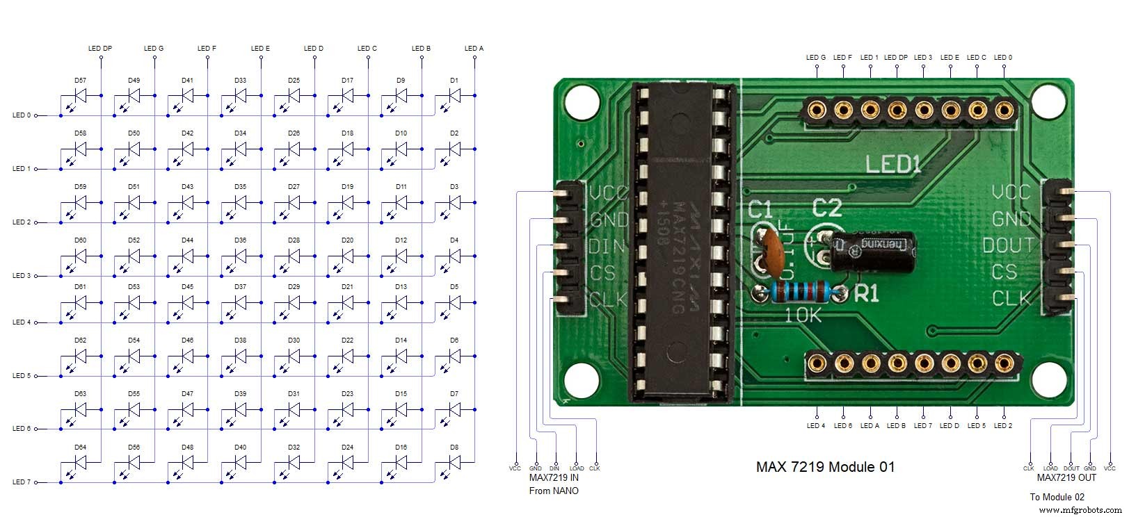 MAX7219 7 segment display module 02 LED connections
 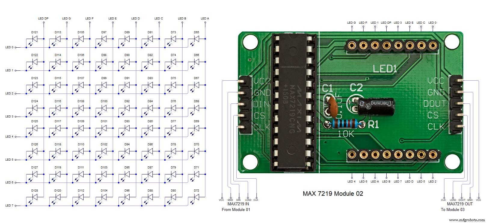 MAX7219 7 segment display module 03 LED connections
 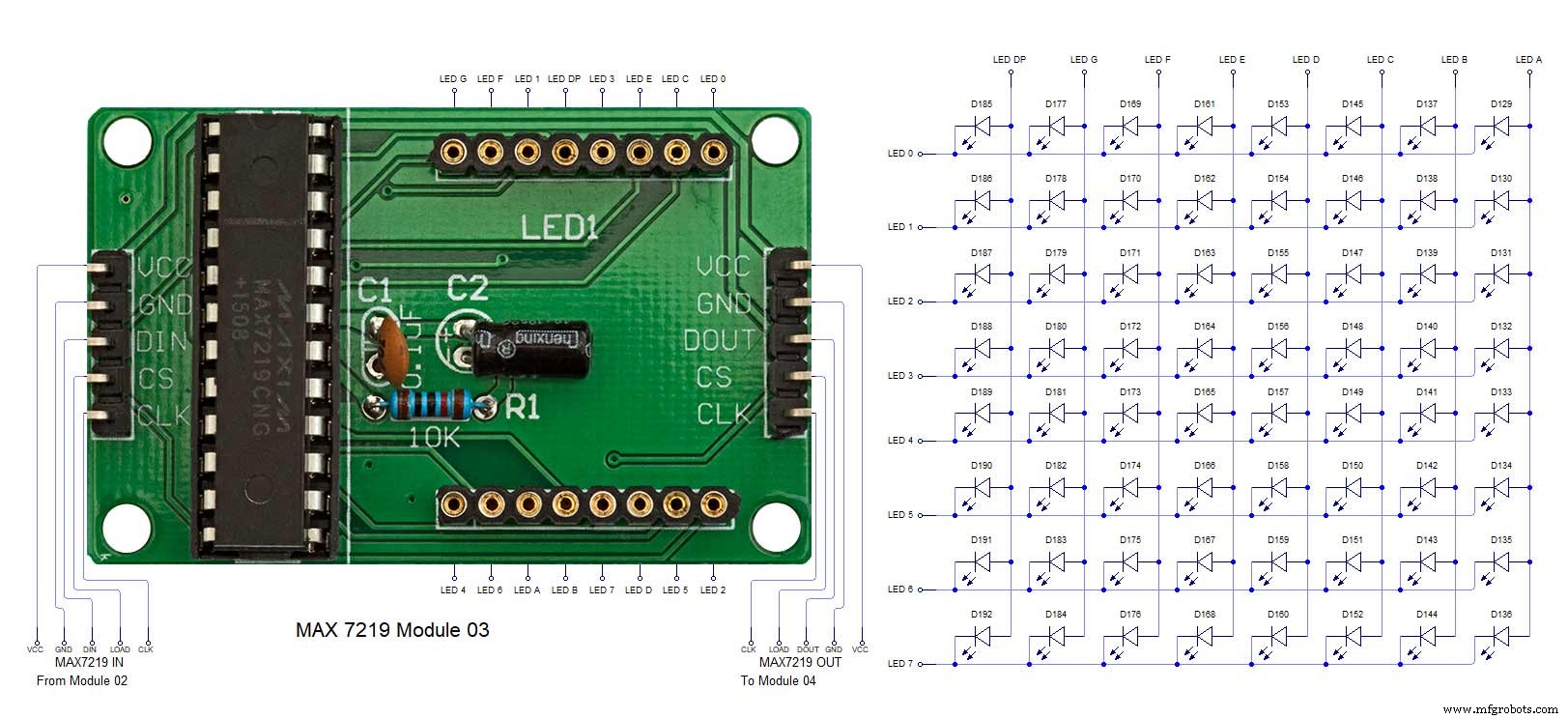 MAX7219 7 segment display module 04 LED connections
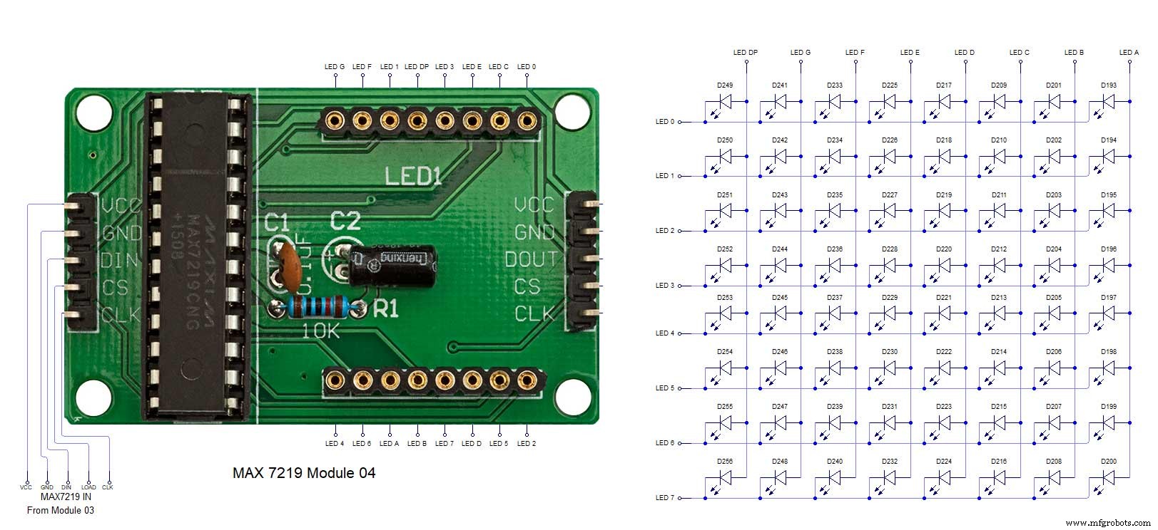
Herstellungsprozess
- Kuckucksuhr
- 3D-Druck mit Silikon – kommt die Zeit?
- Lesen analoger Sensoren mit einem GPIO-Pin
- DIY einfachste IV9 Numitron-Uhr mit Arduino
- Python Timeit() mit Beispielen
- Einfache Wordclock (Arduino)
- Arduino-Uhr mit islamischen Gebetszeiten
- Reduzieren Sie Engpässe mit 5 einfachen Tools
- Arduino-Temp. Monitor und Echtzeituhr mit 3.2 Display
- Einfacher Wecker mit DS1302 RTC