


NEMA-Motoren. Die häufigsten Probleme
Eine der Grundkomponenten in jedem FFF-3D-Drucker sind die Motoren. Sie sind verantwortlich für die notwendigen Bewegungen zur Positionierung des Druckkopfes sowie für das Einziehen des Filaments in den Extruder.
Die verwendeten Motoren sind Schrittmotoren, die gängigsten Typen sind NEMA 17 und NEMA 23.
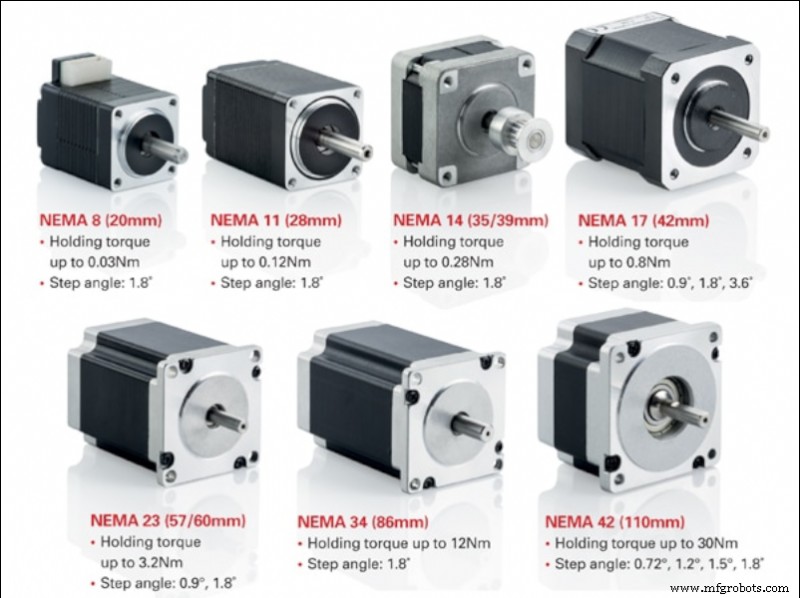
Bild 1:Arten von NEMA-Motoren. Quelle:motioncontrolproducts.com
Schrittmotoren von guter Qualität haben eine sehr hohe Zuverlässigkeit, daher ist die Hauptursache für Motorausfälle normalerweise extern und hängt normalerweise mit dem Leistungstreiber oder der Verbindung zusammen.
Schrittmotoren
Schrittmotoren sind eine Art von kontinuierlich rotierenden Motoren. Die Rotation erfolgt in diskreten Sprüngen eines gegebenen Winkels. Es ist ein Motor auf halbem Weg zwischen einem Standard-Gleichstrommotor und einem Servomotor. Wie Gleichstrommotoren ermöglichen sie mehrere 360 ° -Drehungen und ermöglichen gleichzeitig eine präzise Winkelpositionierung wie Servomotoren.
Am häufigsten werden in 3D-Druckern bipolare Hybrid-Schrittmotoren verwendet, normalerweise im NEMA17- oder NEMA23-Format. Hybridmotoren kombinieren die kleine Schrittmotorfähigkeit von VR-Motoren mit der hohen Trägheitsfähigkeit von Permanentmagnetmotoren. Andererseits bieten bipolare Motoren ein höheres Drehmoment und eine höhere Verankerung als unipolare Motoren, während sie leichter und kleiner sind, jedoch erfordern sie spezielle Leistungsregler.
Bei der Auswahl eines Schrittmotors müssen wir seine Hauptmerkmale kennen:
- Schritt: Dies ist der minimale Winkel, um den sich der Motor direkt drehen kann (ohne die Verwendung von Mikroschrittsteuerungen). Normalerweise finden wir Motoren mit Schritten von 1,8 º oder 0,9 º. Im Allgemeinen bedeutet ein kleinerer Schritt eine höhere Präzision, aber auch eine geringere maximale Drehzahl.
- Arbeitsstrom: Dies ist der maximale Stromwert, bei dem wir den Motor speisen müssen, damit er richtig funktioniert. Je mehr Strom wir an den Motor anlegen, desto mehr Drehmoment erreichen wir und daher kann er einer größeren Trägheit standhalten, ohne Schritte zu verlieren, es treten jedoch auch eine stärkere Erwärmung und ein größerer Verschleiß auf. Die Verwendung von Strömen, die höher als die vom Hersteller angegebenen sind, führt zu einer Verschlechterung und einem Ausfall des Motors.
- Spannung pro Phase: Dies ist die Spannung, die jede der Spulen benötigt, um korrekt zu funktionieren.
- Phasenwiderstand: Dies ist der elektrische Widerstand, den jede der Spulen bereitstellt.
- Phaseninduktivität: Der maximale Induktivitätswert, der von jeder der Spulen bei Aktivierung erzeugt wird.
- Positionierungsgenauigkeit: Die maximale Abweichung, die bei einer Drehbewegung auftreten kann. Im Allgemeinen steht ein niedrigerer Wert für eine höhere Genauigkeit.
- Maximale Betriebstemperatur: Dies ist die maximale Betriebstemperatur, der der Motor standhalten kann. Eine längere Überschreitung dieser Temperatur führt zum Ausfall des Motors.
- Rotorträgheit: Dies ist die Trägheit, die der Rotor aufgrund seines Eigengewichts im leeren Zustand bereitstellt. Die vom Motor getragene Trägheit ist die Summe dieser Trägheit plus der der mit dem Motor gekoppelten Elemente.
- Drehmoment oder Haltemoment: Dies ist das maximale Drehmoment, dem der Motor standhalten kann, wenn die Phasen inaktiv sind (kein Strom), ohne dass sich die Welle dreht.
- Ankerdrehmoment: Dies ist das maximale Drehmoment, dem der Motor standhalten kann, wenn er gestoppt ist und die Phasen aktiv (unter Spannung) sind, ohne dass sich die Welle dreht. Der Wert gilt für einen maximal bestromten Motor.
- Startmoment: Dies ist das Drehmoment, das erforderlich ist, um die Trägheit des Rotors zu überwinden, damit er sich zu drehen beginnt.
- Drehmoment: Dies ist das maximale Drehmoment, dem der Motor standhalten kann, wenn er sich dreht, ohne dass es zu Schrittverlusten kommt. Der Wert gilt für einen maximal bestromten Motor.
Wenn wir nach einem Motor suchen, der es uns ermöglicht, hohe Geschwindigkeiten zu verwenden und hohen Trägheiten während der Bewegung standzuhalten, beispielsweise bei XY-Achsen, sollten wir einen Motor mit 1,8º-Schritten und hohem Drehmoment wählen.
Der Z-Achsen-Motor erfordert keine hohen Arbeitsgeschwindigkeiten, sodass ein 0,9-Grad-Motor für sanftere Bewegungen sorgt. In diesem Fall sollte ein Motor mit maximalem Halte- und Verankerungsmoment gewählt werden, um das Gewicht der Plattform oder des Portals (je nach Ausführung des Druckers) zu tragen.
Anschluss von bipolaren Schrittmotoren
Für den korrekten Anschluss von Schrittmotoren ist es hilfreich, das Datenblatt des Herstellers zur Hand zu haben, da die Position der Kabel von Modell zu Modell unterschiedlich ist.
Typischerweise hat ein bipolarer Schrittmotor 4 Anschlüsse, die aus zwei unabhängigen Stromversorgungskreisen bestehen. Jeder Stromkreis besteht aus einem positiven und einem negativen Pol, die jede der Spulen des Motors mit Strom versorgen.
Das erste, was Sie wissen müssen, ist die Position dieser vier Anschlüsse auf unserer Druckersteuerplatine. Wir können zwei Arten von Nomenklaturen auf den Kontrolltafeln finden. Die erste ist 1A 1B 2A 2B, wobei jede Zahl einen Stromkreis darstellt und die Buchstaben A und B die Pole darstellen. Das zweite ist A A - B B - wobei jeder Buchstabe einen Stromkreis darstellt und der Akzent den Minuspol darstellt.
Sobald die Anschlüsse auf der Platine festgelegt sind, muss dasselbe für die Motoren durchgeführt werden.
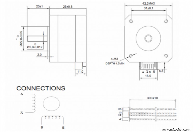
Bild 2. Beispiel für Anschlüsse auf einem NEMA17-Motorspezifikationsblatt. Quelle:Bondtech
Wenn ein Datenblatt verfügbar ist, sollte die Reihenfolge der Drähte im Stecker zu Rate gezogen werden. In diesem Fall die Nomenklatur A A - B B - ist am häufigsten.
Für den Fall, dass die Platine und der Motor die gleiche Nomenklatur verwenden, ist die Verbindung so einfach wie das Koppeln jeder Klemme. Wenn sie unterschiedliche Nomenklaturen verwenden, müssen sie wie folgt gepaart werden:
- 1A - A
- 1B - A -
- 2A - B
- 2B - B -
Liegt kein Motordatenblatt vor, muss das Anschlusspaar jeder Spule ermittelt werden. Dazu wird der Widerstand an allen möglichen Kombinationen von Steckerstiftpaaren gemessen. Wenn der Widerstand nicht unendlich ist, wurde das erste Paar lokalisiert. Die von Motorherstellern am häufigsten verwendeten Kombinationen sind 1-3 4-6 oder 1-4 3-6, also testen Sie zunächst diese beiden Kombinationen.
Einmal lokalisiert, wird jede Phase mit jeder der Spulen verbunden. Es ist wichtig, dass die beiden Phasen mit der gleichen Polarität an die Spulen angeschlossen sind. Wenn wir sie also in umgekehrter Phase platziert haben, bewegt sich der Motor beim Senden von Strom nicht und gibt ein Geräusch ab. In diesem Fall muss die Polarität einer der Spulen umgekehrt werden.
Es ist sehr wichtig, beide Phasen getrennt zu halten, daher sollte der Zustand der Steckverbinder regelmäßig überprüft werden. Ein schlechter Kontakt oder eine Brücke zwischen den Phasen führt dazu, dass der Motor nicht mehr funktioniert.
Einstellen des Stroms der Motoren
Schrittmotoren werden über spezielle Controller oder Treiber mit Strom versorgt. Es gibt viele verschiedene Modelle auf dem Markt. Die qualitativ hochwertigeren bieten im Allgemeinen eine längere Haltbarkeit und einen leiseren Betrieb.
Innerhalb der verfügbaren Modelle gibt es zwei Methoden zur Anpassung des an die Motoren gesendeten Stroms:
- Durch eine Stellschraube. In general, lower quality or cheaper drivers allow the output current to be adjusted by means of a potentiometer in the form of a screw. In this case it is necessary to use a multimeter and a precision ceramic screwdriver to make the adjustment.
In this case the adjustment can be made in two ways:
- By Current:With the printer switched on and the motors connected, the current in one of the phases will be measured and adjusted to the appropriate value. This method is not recommended, especially the first time a new driver is connected, as the motors are initially powered without knowing if the output current is higher than the current admitted by the motor.
- By reference voltage:This is a slightly more complex method, but more recommendable. First we must determine the required reference voltage using the formula:
max · 8 · Rs
Where Imax is the maximum current at which the motor will be powered (usually at most 90 % of the maximum specified by the manufacturer) and Rs is the detection resistance of the driver.
To adjust it on the driver, simply power up the driver, measure the voltage between the Vref pin (usually the potentiometer itself) and a ground pin (usually the power supply pin) and set the appropriate value using the potentiometer.
- By firmware: Many current drivers do not have an adjustment potentiometer and allow the output current to be set directly by firmware. To do this, simply set the appropriate current value in the motor section of the firmware.
When selecting the output current of the drivers, it is not advisable to use the maximum value determined by the manufacturer. In order to prolong the service life of the motors, do not exceed 90 % of the manufacturer's maximum value, the optimum being the minimum current required to generate sufficient torque to withstand the inertias.
Higher current, in addition to higher torque, also means higher heating, higher motor noise and higher wear.
Maximum speed of a stepper motor
Stepper motors advance by pulses, so the maximum speed of the motor will depend on the maximum signal frequency that the control board is able to send. In addition, it must be taken into account that usually several motors are working simultaneously, so the frequency for each one will decrease.
For example, if the control board works at 100000 Hz and 4 motors (X,Y,Z and extruder) are working simultaneously, each motor will be controlled at 25000 Hz, or 25000 pulses per second. This means that a 1.9 ° motor without microstepping can rotate at a maximum of 125 rps. In a GT2 8-tooth belt drive system (the most common) this translates into a theoretical maximum linear speed of 3600 mm/s.
In the case of microstepping, the maximum speed would be reduced proportionally, so that if 16 microsteps are used, the maximum speed would be 225 mm/s, but if 256 microsteps are used, it would be reduced to only 14 mm/s.
It is very important to know the operating frequency of the control board, as the combination of a low output frequency with a high microstep setting can cause the maximum allowable speed to be lower than the printing speed, resulting in a significant loss of steps.
Appropriate setting of the steps per mm
When the motion signal is transmitted to the motor, it is sent as a rotation, however the movements included in the print files are linear. This is why the printer must be able to translate the angular movement into a linear one.
The movement is generally transmitted by means of toothed pulleys and belts, so that the step/mm conversion depends on the diameter of the pulleys.
To calculate this, the following formula is simply applied:
steps/mm = (360/P) · MS
2 · π · Rpulley
Where P is the motor pitch, MS the configured microsteps (1 in case of not using microstepping) and Rpulley the radius of the pulley used.
In the case of screw-transmitted movements, it is the pitch of the screw that defines the feed rate. For this purpose, the following formula is simply applied:
steps/mm = (360/P) · MS
A
Where P is the motor pitch, MS the configured microsteps (1 in case of not using microstepping) and A the pitch of the screw thread.
There are also many calculators that make it easier to obtain these values, such as the one offered by Prusa Printers.
Once these values have been obtained, and although in theory they are correct, it is advisable to carry out a precise calibration to compensate for possible manufacturing or assembly defects.
For this purpose, a cube of known dimensions (e.g. 50 x 50 x 50 mm) shall be printed out and the actual dimensions measured. Once this is done, the following formula shall be applied:
steps/mm = Dtheorical · Pactual
Dreal
where Dtheorical is the theoretical size that the part should have, Pactual is the current P/mm setting and Dreal is the measurement value obtained from the printed part.
By introducing the new P/mm value, you should obtain parts with appropriate dimensions.
Considerations to take into account
- Step loss: A step loss is usually caused by excessive torque in the engine. Large accelerations or high direction change speeds will cause inertias that the motor torque cannot compensate for, resulting in a step loss. Similarly, the combination of low signal frequencies and high microstep settings will drastically reduce the maximum motor speed. If the print speed exceeds this, a step loss will also occur. In any case, step loss in an open-loop printer will result in loss of position.
- Temperature: A high current setting will cause the motor to heat up. If the motor is inside a closed or heated structure that does not allow the heat to dissipate correctly, the working temperature may be exceeded, causing the demagnetisation of the magnets and a malfunction or breakdown of the motor. In closed printers, it is advisable to place the motors outside the chamber or, if this is not possible, to reduce the current to the minimum necessary.
- Hysteresis: This is a phenomenon intrinsic to motors. It can cause a small position error at the end of a movement. Using quality motors will reduce this error.
- Resonance: All motors have a natural frequency. If the pulse frequency sent to the motor is similar to the natural frequency, a resonance effect will occur. This will cause increased vibration, noise and wear.
- Step settings: Improper step/mm settings will result in positioning error, which will be reflected in dimensional errors in the parts.
- Connection: Mixing or bridging phases will cause the motor to not turn or to turn erratically. Placing one phase with the polarity reversed with respect to the other will cause the motor not to turn. Reversing the polarity of both phases, when connected correctly, will cause the motor to rotate in the opposite direction.
This guide discusses concepts in a general way and does not focus on a particular make or model, although they may be mentioned at some point. There may be important differences in calibration or adjustment procedures between different makes and models, so it is recommended that the manufacturer's manual be consulted before reading this guide.
3d Drucken
- Einphasen-Asynchronmotoren
- AC-Kommutatormotoren
- Technischer Tipp:Motoren
- Elektromotorsicherheit:Verschiedene Phasen und Sicherheitsmaßnahmen
- Die häufigsten Probleme und Lösungen für Gerber-Dateien
- Über Industriemotoren und Anwendungen
- Eine Einführung in den BLDC-Motor
- 5 Gründe, warum TEFC-Motoren ausfallen
- Richtige Wartung von Kompressormotoren
- Welche Art von Hydraulikmotor ist am effizientesten?