



DIY Lötkolben-Controller für 862D+ – Präzision & Zuverlässigkeit
Komponenten und Zubehör
| Arduino Nano R3 | 1 |
| Normale Freilaufdiode | 1 |
| IRF540N N-Kanal MOSFET | 1 |
| 5V Linearregler | 1 |
| Widerstand 330 Ohm | 1 |
| Stiftleisten (male) | 2 |
| 0,96 Zoll OLED-Display | 1 |
Benötigte Werkzeuge und Maschinen
- Lötkolben (allgemein)
- 8 mm Bohrer / Bohrmaschine
Über dieses Projekt
Update (21.10.2019): Großes Code-Update. Unten mehr dazu – einiges hat sich geändert.
Mein 862D+ Lötkolben war defekt. Statt einen neuen zu kaufen, nahm ich einen zweiten Kolben und reparierte ihn. Das Schwierigste: Es gab keine Lösung im Netz. Die Platine war defekt, denn nach dem Austausch des Kolbens zeigte er immer noch „S-E“ (Sensorfehler).

Also entschied ich mich, einen eigenen Controller zu bauen und in das Gehäuse einzubauen. Es brauchte einen zweiten Trafo, aber da das Gerät billig war, war genug Platz innen.


Sieht vielleicht nicht schön aus, funktioniert aber einwandfrei. Als Bonus entfernte ich den Netzschalter des Lötkolbens und schaltete ihn zwischen 5V und den Arduino.
Bautipps
- Alle Teile sind jetzt erhältlich. LCSC ist ein Großhändler für Elektronik. Versand nach Amerika ist teuer, aber die Bauteile sind extrem günstig. Beispiel: MOSFET auf Amazon 6 $, bei LCSC 32 Cent. Widerstände müssen in Großpackungen gekauft werden – 50 Stück kosten aber nur 0,84 Cent.
- LANGE DATENLEITUNGEN ABDECKEN mit geerdeter Alufolie oder Ähnlichem. Z. B. die I2C-Leitung zum Display.
- Im Code: 1023 = kältest, 0 = Lava.
settempauf Wunschtemperatur setzen. Typischerweise ca. 600. - Der Controller erkennt, ob der Kolben angeschlossen oder defekt ist. Wenn der Kolben getrennt ist, setzt der Arduino den Analogeingang auf null. Wenn der Kolben früher richtig heizte, es jetzt aber nicht mehr tut: Kolben trennen, warten bis „Kolben anschließen“ erscheint, dann wieder anschließen – dann geht es. (Das war ein Problem bei mir.)
Jetzt kennen Sie die Grundlagen. Das kann eine günstige Alternative zu einem Qualitäts-Lötkolben sein. Es gibt hochwertigere, aber dieser ist sehr billig und DIY.
Code
- Control Code (C/C++)
- The Code (C/C++)
- Code Updated 10/21/2019 (C/C++)
Control Code (C/C++)
In Arduino IDE einfügen und hochladen. Funktioniert nur mit der angegebenen Schaltung.
int output = 0;
int temp = 0;
int settemp = 630;
String inputString = "";
boolean rap = false;
boolean stringComplete = false;
int t = 0;

void setup() {
  Serial.begin(9600);
  inputString.reserve(200);
  pinMode(6, OUTPUT);
  digitalWrite(6, LOW);
}

void loop() {
  serialEvent();
  if (stringComplete) {
    Serial.println(inputString);
    t = inputString.toInt();
    // settemp = t // Settemp auf seriellen Input setzen
    inputString = "";
    stringComplete = false;
  }
  rapid();
  pid();
}

void rapid() {
  // Schnelles Aufheizen am Anfang
  if (rap == false) {
    digitalWrite(6, HIGH);
    do {
      temp = analogRead(0);
      Serial.print("rapid");
      Serial.println(temp);
    } while (temp - settemp > 10);
    digitalWrite(6, LOW);
    rap = true;
  }
}

void pid() {
  // Langsame, aktive Leistungsregelung
  temp = analogRead(0);
  output = temp - settemp;
  if (output < 0) output = 0;
  if (output > 255) output = 255;
  Serial.print("pid");
  Serial.print(temp);
  Serial.print(", ");
  Serial.println(output);
  analogWrite(6, output);
}

void serialEvent() {
  // Serielle Kommunikation zum Aktualisieren von settemp
  while (Serial.available()) {
    char inChar = (char)Serial.read();
    inputString += inChar;
    if (inChar == '\n') {
      stringComplete = true;
    }
  }
}
The Code (C/C++) – mit OLED-Display
#include <Wire.h>
#include <Adafruit_SSD1306.h>
#include <Adafruit_GFX.h>
#define OLED_ADDR 0x3C
Adafruit_SSD1306 display(-1);

int settemp = 590;
int output = 0;
int temp = 0;
String inputString = "";
boolean rap = false;
boolean stringComplete = false;
int t = 0;
int mappedpower = 0;
byte powermultiply = 0;
long counter = 0;
int temp2 = 0;
byte outputoffset = 0;
byte scaleread = 0;

void setup() {
  Serial.begin(9600);
  pinMode(12, OUTPUT);
  digitalWrite(12, LOW);
  display.begin(SSD1306_SWITCHCAPVCC, OLED_ADDR);
  display.clearDisplay();
  display.display();
  rapid();
}

void loop() {
  pid();
  display.clearDisplay();
  updatebar();
  updatetext();
  display.display();
}

void rapid() {
  if (rap == false) {
    digitalWrite(12, HIGH);
    output = 255;
    do {
      temp = analogRead(0);
      Serial.print("rapid");
      Serial.println(temp);
      display.clearDisplay();
      updatebar();
      updatetext();
      display.display();
    } while (temp - settemp > 1);
    digitalWrite(12, LOW);
    rap = true;
  }
}

void pid() {
  temp = analogRead(0);
  // Temperatur mitteln
  temp2 = temp;
  delay(50);
  temp = analogRead(0);
  temp = (temp + temp2) / 2;
  zeroscale(); // Kein-Kolben-Prüfung
  temp = temp + outputoffset;
  output = temp - settemp;
  output = output + powermultiply;
  output = output * 4;
  if (output < 0) output = 0;
  if (output > 255) output = 255;
  counter++;
  if (counter > 10) {
    counter = 0;
    if (temp > settemp + 3) powermultiply++;
    if (temp < settemp - 3 && powermultiply > 0) powermultiply--;
  }
  Serial.print(powermultiply);
  Serial.print(", ");
  Serial.print(temp);
  Serial.print(", ");
  Serial.println(output);
  analogWrite(12, output);
}

void updatebar() {
  mappedpower = map(output, 0, 255, 0, 127) - 10;
  display.fillRect(0, 0, mappedpower, 8, WHITE);
  display.fillRoundRect(mappedpower - 5, 0, 20, 8, 3, WHITE);
}

void updatetext() {
  display.setCursor(0, 9);
  display.setTextColor(WHITE);
  display.setTextSize(1);
  display.print("Set Temp: ");
  display.print(settemp);
  display.setCursor(0, 20);
  display.print("Temp: ");
  display.print(temp);
}

void zeroscale() {
  if (output < 200) {
    display.clearDisplay();
    display.setCursor(0, 9);
    display.setTextColor(WHITE);
    display.setTextSize(1);
    display.print("No soldering iron, or defective");
    display.setCursor(0, 15);
    display.print("iron.");
    display.setCursor(0, 20);
    display.print("Testing in 5 seconds.");
    display.display();
    delay(5000);
    if (output < 200) {
      outputoffset = temp;
    }
    display.clearDisplay();
    display.setCursor(0, 9);
    display.setTextColor(WHITE);
    display.setTextSize(1);
    display.print("Output offset set.");
    display.setCursor(0, 20);
    display.print("Please plug in the iron.");
    display.display();
    do {
      scaleread = analogRead(0);
    } while (scaleread < 200);
  }
}
Code Updated 10/21/2019 (C/C++) – verbesserte Erkennung
#include <Wire.h>
#include <Adafruit_SSD1306.h>
#include <Adafruit_GFX.h>
#define OLED_ADDR 0x3C
Adafruit_SSD1306 display(-1);

int settemp = 590;
int output = 0;
int temp = 0;
String inputString = "";
boolean rap = false;
boolean stringComplete = false;
int t = 0;
int mappedpower = 0;
byte powermultiply = 0;
long counter = 0;
int temp2 = 0;
byte outputoffset = 0;
byte scaleread = 0;

void setup() {
  Serial.begin(9600);
  pinMode(12, OUTPUT);
  digitalWrite(12, LOW);
  display.begin(SSD1306_SWITCHCAPVCC, OLED_ADDR);
  display.clearDisplay();
  display.display();
  rapid();
}

void loop() {
  pid();
  display.clearDisplay();
  updatebar();
  updatetext();
  display.display();
}

void rapid() {
  if (rap == false) {
    digitalWrite(12, HIGH);
    output = 255;
    do {
      temp = analogRead(0);
      Serial.print("rapid");
      Serial.println(temp);
      display.clearDisplay();
      updatebar();
      updatetext();
      display.display();
    } while (temp - settemp > 1);
    digitalWrite(12, LOW);
    rap = true;
  }
}

void pid() {
  temp = analogRead(0);
  temp2 = temp;
  delay(50);
  temp = analogRead(0);
  temp = (temp + temp2) / 2;
  zeroscale();
  temp = temp + outputoffset;
  output = temp - settemp;
  output = output + powermultiply;
  output = output * 4;
  if (output < 0) output = 0;
  if (output > 255) output = 255;
  counter++;
  if (counter > 10) {
    counter = 0;
    if (temp > settemp + 3) powermultiply++;
    if (temp < settemp - 3 && powermultiply > 0) powermultiply--;
  }
  Serial.print(powermultiply);
  Serial.print(", ");
  Serial.print(temp);
  Serial.print(", ");
  Serial.println(output);
  analogWrite(12, output);
}

void updatebar() {
  mappedpower = map(output, 0, 255, 0, 127) - 10;
  display.fillRect(0, 0, mappedpower, 8, WHITE);
  display.fillRoundRect(mappedpower - 5, 0, 20, 8, 3, WHITE);
}

void updatetext() {
  display.setCursor(0, 9);
  display.setTextColor(WHITE);
  display.setTextSize(1);
  display.print("Set Temp: ");
  display.print(settemp);
  display.setCursor(0, 20);
  display.print("Temp: ");
  display.print(temp);
}

void zeroscale() {
  if (temp < 200) {
    display.clearDisplay();
    display.setCursor(0, 20);
    display.setTextColor(WHITE);
    display.setTextSize(1);
    display.print("No soldering iron.");
    display.display();
    delay(10000);
    display.setCursor(0, 0);
    display.print("Testing in 5 seconds.");
    display.display();
    delay(5000);
    if (temp < 200) {
      outputoffset = temp;
    }
    display.clearDisplay();
    display.setCursor(0, 20);
    display.setTextColor(WHITE);
    display.setTextSize(1);
    display.print("Output offset set.");
    display.setCursor(0, 0);
    display.print("Connect the iron.");
    display.display();
    do {
      scaleread = analogRead(0);
    } while (scaleread < 200);
  }
}
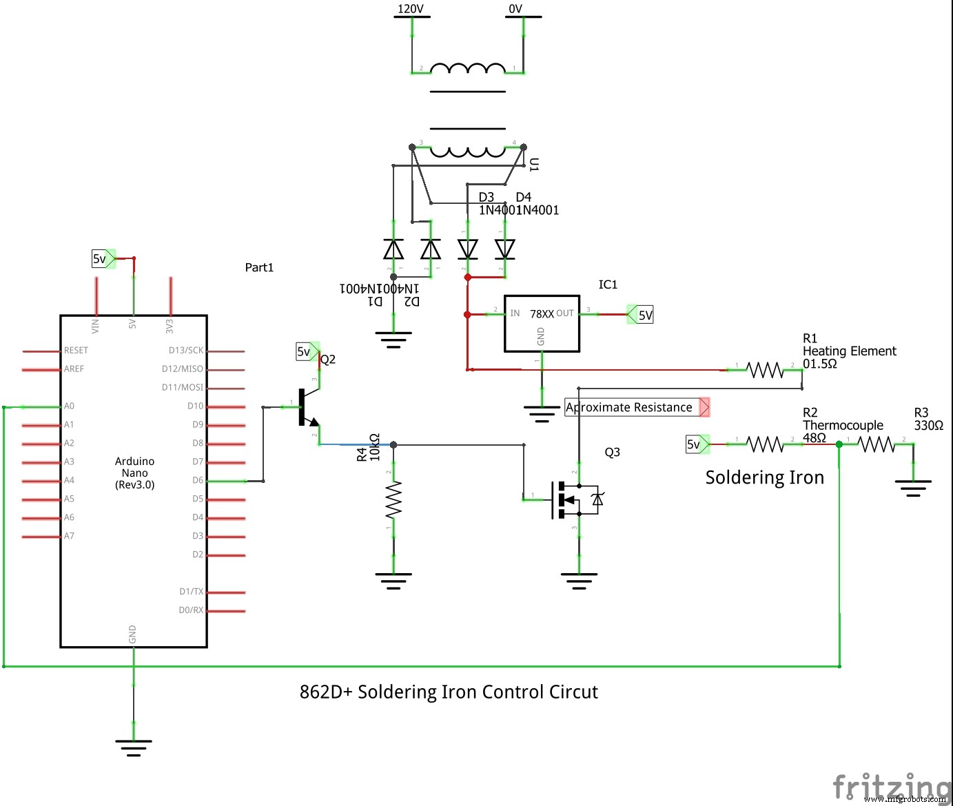
Schaltplan
Diesen Schaltplan nutzen, um die Schaltung für den Lötkolben zu erstellen:
Herstellungsprozess
- Multi-Position Temperatursensor-System für Smart-Home-Integration
- 37-LED-Roulette-Spiel mit Arduino Nano bauen – Europäisches Layout
- MotionSense: Smarte Einbruchserkennung mit Arduino & ESP8266
- 3D-Drucker Brandschutz: Intelligentes Sensorsicherheitssystem
- MIDI-Umbau für Digitalorgeln: Komponenten & Anleitung
- Arduino-basierte abstoßende Magnetschwebung: Einfache Schaltung & DIY-Anleitung
- Fortgeschrittener ferngesteuerter Greifer-Roboter für präzises Handling
- Fortgeschrittenes Mikrocontroller-Labor: ESP32, Arduino, PIC und Sensormodule
- DIY Persistence-of-Vision (POV) Globe – LED-Kugel mit Arduino Mega
- CoroFence Thermaldetektor: PIR-Sensor & IoT-Integration mit Panasonic GridEye