Nano- und Batterieanode:Ein Rückblick
Zusammenfassung
Die Verbesserung der Anodeneigenschaften, einschließlich der Erhöhung ihrer Kapazität, ist eine der grundlegenden Notwendigkeiten, um die Batterieleistung zu verbessern. In diesem Beitrag werden Hochleistungsanoden mit Legierungsleistung vorgestellt, dann wird das Problem der Fragmentierung dieser Anoden und deren Auswirkung während der zyklischen Lebensdauer dargelegt. Anschließend wird der Effekt der Verkleinerung auf den Nanobereich bei der Lösung des Fragmentierungsproblems und der Verbesserung der Eigenschaften diskutiert und schließlich die verschiedenen Formen von Nanomaterialien untersucht. In dieser Arbeit wird die Elektrodenreduktion in der Anode beschrieben, die ein nanoskaliges Phänomen ist. Die negativen Auswirkungen dieses Phänomens auf Legierungsanoden werden dargelegt und diskutiert, wie diese negativen Auswirkungen durch die Herstellung geeigneter Nanostrukturen beseitigt werden können. Außerdem werden die Anoden der Titanoxid-Familie vorgestellt und die Auswirkungen von Nano auf die Leistungsverbesserung dieser Anoden ausgedrückt, und schließlich wird das für Nano spezifische quasi-kapazitive Verhalten vorgestellt. Schließlich wird der dritte Anodentyp, die Austauschanoden, vorgestellt und deren Funktion ausgedrückt. Die Wirkung von Nano auf die Reversibilität dieser Anoden wird erwähnt. Die Vorteile der Nanotechnologie für diese Elektroden werden beschrieben. In diesem Beitrag wird festgestellt, dass die Nanotechnologie neben den üblichen Effekten wie Verringerung der Eindringlänge und Modulation der Spannung auch andere interessante Effekte in diesem Anodentyp erzeugt, wie kapazitive Quasi-Kapazität, Änderung des Speichermechanismus und niedrigere Lautstärkeänderung.
Einführung
Graphit ist ein Kohlenstoffmaterial mit einer Schichtstruktur, bei dem der Abstand zwischen den Schichten etwa 35,3 beträgt, in dem ein geeigneter Raum zwischen den Schichten für die Platzierung von Lithiumatomen vorhanden ist [1,2,3,4]. Beim Laden werden Lithiumionen in der Anode reduziert und in Lithiumatome umgewandelt, die sich zwischen den Graphitschichten befinden. Nach dem Eintreffen von Lithium beträgt der Plattenabstand 3,5 Å [5,6,7,8,9,10]. Beim Entladen werden die Lithiumatome zu Lithiumionen oxidiert und durch den Elektrolyten zur Kathode transportiert. Aufgrund des Einbaus von Lithiumatomen in Graphit (zum Zeitpunkt des Ladens) werden diese Materialien als Interkalationsanoden bezeichnet [6,7,8,9,10,11,12,13,14]. Nach Abb. 1 kann in Graphit auf 6 Kohlenstoffatome maximal ein Lithiumatom gespeichert werden [5]. Da die Kapazität in direktem Zusammenhang mit der gespeicherten Lithiummenge steht, hat Graphit eine geringere Kapazität als Lithiummetallanoden, wird jedoch, wie bereits erwähnt, als kommerzielle Anode verwendet, da es keine Probleme beim dendritischen Wachstum aufweist. Beachten Sie, dass in diesem Artikel und zukünftigen Artikeln Anode und Kathode den Wirkstoff in Anode und Kathode bedeuten [6,7,8]. Aufgrund der geringen Kapazität von Graphit werden Anoden mit hoher Kapazität benötigt [15,16,17,18]. Eine Gruppe von Anoden, die große Mengen an Lithiumatomen speichern können, sind legierungsartige Anoden aus Metall oder Halbleitern. Die Funktion dieser Anoden besteht darin, eine Legierung mit einem Metall oder Halbleiter zu bilden, wodurch das Lithiumatom gespeichert wird [19,20,21]. Bei dieser Art von Material können im Gegensatz zu Graphit, bei dem nur ein Lithiumatom pro 6 Kohlenstoffatome gespeichert ist, mehrere Lithiumatome für jedes Metallatom gespeichert werden [9,10,11]. Die wichtigsten dieser Anoden sind Silizium und Antimon. Für Silizium beträgt die Kapazität ca. 4000 mAh/g und für Zinn beträgt die genannte Kapazität 900 mAh/g im Vergleich zu Graphit mit einer Kapazität von ca. 350 mAh/g. Gemäß Abb. 2 hat Silizium unter den Legierungsanoden die höchste Volumen- und Gewichtskapazität, kommt in der Natur im Überfluss vor und die gesamte Elektronikindustrie basiert auf Silizium; Somit ist, wie Abb. 2 zeigt, Silizium die wichtigste Legierungsanode [12,13,14,15]. Daher dreht sich das meiste Material in diesem Artikel um Silizium, aber die genannten Prinzipien können auf andere Legierungsanoden verallgemeinert werden. Aktives Anodenmaterial, theoretische Kapazität, Vorteile und Studienergebnisse sind in Tabelle 1 dargestellt.
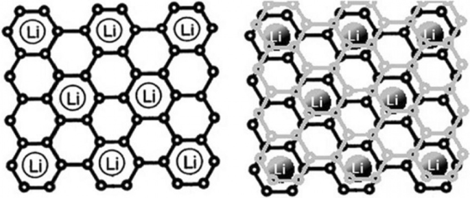
Zeigt, wie Lithium in Graphit gespeichert wird. Für jeweils 6 Kohlenstoffatome wird 1 Lithiumatom gespeichert [12]
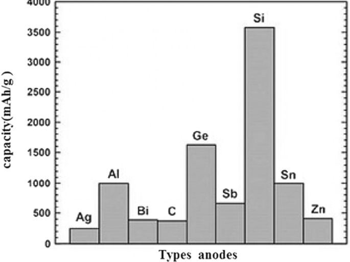
Anodentypen mit Kapazität [13,14,15]
Probleme von Legierungsanoden
Bei diesen Anoden wird die Speicherung und Freisetzung von Lithium von einer großen Volumenänderung begleitet, die bis zu 400 % des Ausgangsvolumens erreichen kann, wie in Abb. 3 gezeigt. Während des Arbeitszyklus wird aufgrund der durch die Volumenänderung verursachten Spannungen das Phänomen der Pulverisierung von Wirkstoffen tritt auf [7, 10, 39, 40]. Durch die Fragmentierung wird die Verbindung zwischen dem aktiven Material selbst, zwischen dem aktiven leitfähigen Additivmaterial und zwischen dem wirkstoffsammelnden Wirkstoff unterbrochen [18,19,20]. Wenn dieses Phänomen auftritt, wird der Wirkstoff elektrisch isoliert; daher findet kein Elektronentransfer statt, um die Oxidationsreaktion durchzuführen. Daher bleibt ein großes Volumen an Wirkstoffen ungenutzt und nimmt nicht an der Kapazität teil, was letztendlich zu einem starken Kapazitätsabfall während des Arbeitszyklus führt [21, 41, 42]. Abbildung 3 zeigt das Quetschphänomen. Leider zeigt Abb. 3 nicht die gesamte Struktur der Anodenelektrode. Tatsächlich werden in einer herkömmlichen Elektrode Mikron-Partikel von Aktivmaterialien zusammen mit Bindemitteln und leitfähigen Kohlenstoffmaterialien usw. verwendet [43,44,45,46]. Was kaputt ist, wenn die oben genannten elektronischen Verbindungen unterbrochen sind. Abbildung 4 zeigt die Lade- und Entladekurven für Siliziumpartikel mit einer Größe von 10 Mikron. Es ist zu erkennen, dass die Kapazität selbst bei der ersten Entladung nur 800 mAh/g beträgt (im Vergleich zu den anfänglichen 4000 geladenen). Bei Graphit hingegen sinkt die Kapazität nur um 0,03 pro Arbeitsspiel. Diese Anoden haben eine höhere Spannung als Graphit (nach der oben genannten Formel gilt:je höher die Anodenspannung, desto niedriger die Batteriespannung) [10, 21, 39]. Silizium hat beispielsweise eine um 0,3 bis 0,4 höhere Spannung als Lithium, während bei Graphit die Spannung etwa 0,05 V höher als bei Lithium ist, aber Silizium- und andere Legierungsanoden haben eine so hohe Kapazität, dass die Spannung keinen signifikanten Einfluss hat, und die Energie ist deutlich höher als bei Graphit.
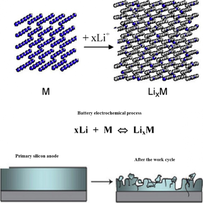
Pulverisieren und Trennen des elektrischen Anschlusses [10]
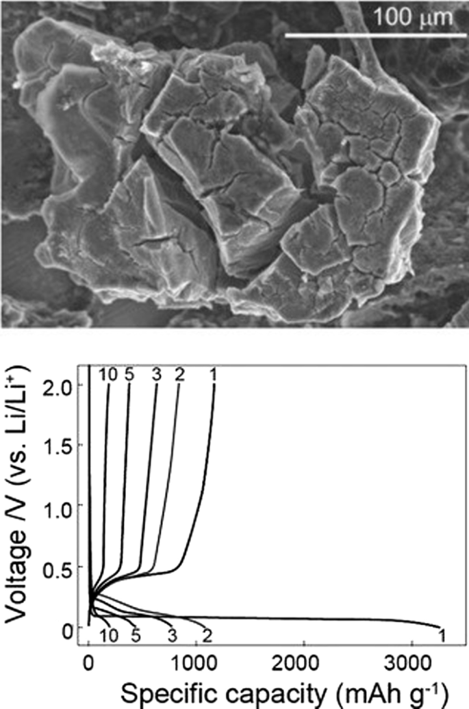
Lade- und Entladediagramm für 10-Mikron-Siliziumpartikel [17]
Nanotechnologie-Lösung
Die Akkuleistung kann verbessert werden, wenn das Zerkleinerungsphänomen auf irgendeine Weise verhindert werden kann. Untersuchungen haben gezeigt, dass das Zerkleinerungsphänomen nicht mehr auftritt, wenn die Abmessungen von Silizium den Nanometerbereich (weniger als 150 nm) erreichen [47,48,49,50]. Abbildung 5 zeigt das TEM-Bild von Silizium-Nanopartikeln während der Lithiumionisation. Diese beiden Partikel verändern durch den Lithiumeintrag ihr Volumen, brechen aber nicht unter Belastung [7, 18, 40]. Dies zeigt, dass wir, um die außerordentliche Kapazität von Silizium zu nutzen, zwangsläufig in den Nanobereich gehen müssen [51,52,53]. Bei der Verwendung von Nanopartikeln ist das Problem der Fragmentierung gelöst, diese sind jedoch normalerweise nicht an die Elektronenversorgung angeschlossen. Daher verwendeten die Forscher zum ersten Mal vertikal auf einem Stromkollektor gewachsene Silizium-Nanodrähte, wie in Abb. 6 (REM-Bild) gezeigt. Auf diese Weise kann das Problem des Quetschens gelöst werden, da zwischen den Nanodrähten genügend Platz vorhanden ist, um das Volumen jedes Nanodrahts während des Arbeitszyklus zu ändern, ohne große Spannungen zu erzeugen, der Durchmesser jedes Nanodrahts ist auch kleiner als das kritische Maß [19 ,20,21,22, 30, 54,55,56]. Bekanntlich nimmt nach dem Legieren (Eintrag von Lithium) die Breite der Nanodrähte zu und die Seitenwände werden texturiert, wobei trotz einer großen Volumenänderung keine Fragmentierung auftrat [57]. Bei Nanodrähten findet der Elektronentransfer (Kommunikation zwischen Stromkollektor und Wirkstoff) über die Länge der Nanodrähte statt. Da der Elektronentransfer gut ist, kann die volle Kapazität des Siliziumaktivmaterials genutzt werden [31, 32, 35, 36, 37]. Nanodrähte haben eine höhere Elektrolytbindungssaison als Bulkmaterial [41,42,43]. Aufgrund der Tatsache, dass die Oxidationsreaktion durch die Elektrode-Elektrolyt-Grenzfläche erfolgt, erhöht sich auch die Reaktionsgeschwindigkeit. Andererseits ist der Ionentransfer durch laterale Dimensionen einfach, da Nanodrähte im Vergleich zum Volumenmaterial, das Ionen über längere Strecken zurücklegen müssen, kleine Abmessungen haben. Schnellere Ionentransfers und Oxidationsreaktionen erhöhen die Leistung und sogar die Energie, da der Ionentransfer (manchmal zusätzlich zum Elektronentransfer) ein potentieller Verlust (Konzentrationspolarisation) sowohl der Anoden- als auch der Kathodenelektrode einer Lithiumbatterie ist, diese Polarisation nimmt mit der Eindringstrecke ab nimmt ab und die Energiedichte verbessert sich [44,45,46]. Da Silizium schließlich ein Halbleiter ist, hat es eine geringere Elektronenleitfähigkeit als Graphit, das ein Halbmetall ist [33, 38, 58].
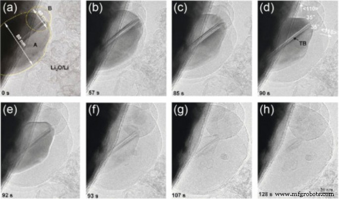
TEM-Aufnahme von Silizium-Nanopartikeln während der Lithiumionisation von a bis h it Lithiumionisation bzw. [19]
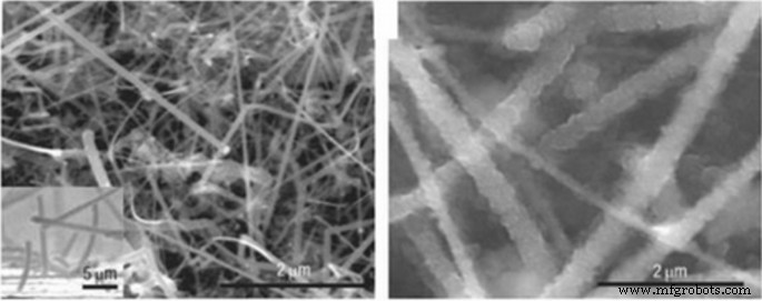
SEM-Aufnahme von Silizium-Nanopartikeln während Lithium [20]
Verschiedene Nanomorphologien
Es hat sich gezeigt, dass die Verwendung von Silizium-Nanoröhren anstelle von Nanodrähten effektiver ist. Bei Nanotubes wird der notwendige Raum für die Volumenänderung auf beiden Seiten der Innen- und Außenwand bereitgestellt [34, 59, 60, 61]. Darüber hinaus sind Nanoröhren in der Regel dünner als Nanodrähte, daher sind Sender besser geeignet, da Silizium ein Halbleiter ist und aufgrund von Spannungen während des Arbeitszyklus auch amorph ist, leitet es während des Arbeitszyklus elektronisch nicht gut [47, 48, 54]. Infolgedessen fließen Elektronen nicht in allen Teilen des Siliziums gut. Zur Lösung dieses Problems können hybride Nanostrukturen verwendet werden, beispielsweise eine Silizium-Nanoröhre, deren Kern leitfähige Materialien enthält oder umgekehrt eine leitfähige Beschichtung aufweist [62,63,64,666]. Ein Vergleich zwischen den beiden Kategorien von unbeschichteten und kohlenstoffbeschichteten Silizium-Nanodrähten hat gezeigt, dass kohlenstoffbeschichtete Nanodrähte eine beträchtliche Kapazität behalten. Eine andere Lösung ist die Verwendung von Nanokomposit-Anoden [49,50,51]. Eines der am häufigsten verwendeten Materialien in Nanokompositen als Stressmodulator (Puffer) ist Kohlenstoff. Kohlenstoff-Nanokomposit beispielsweise im Bereich Kohlenstoff ist eine der Lösungen für das Stressproblem. Abbildung 7 zeigt ein Zinn-Kohlenstoff-Nanokomposit. Zinn wirkt als Wirkstoff als Legierungsanode. Kohlenstoff in diesem Nanokomposit fungiert sowohl als Puffer als auch als Leiter und kann zusätzlich zu seinen verschiedenen Kohlenstoffstrukturen etwas Lithium speichern. Wie in Abb. 7 gezeigt, ist die Zinnkapazität aufgrund des Vorhandenseins von Kohlenstoff geringer als die theoretische Kapazität (900 mAh/g), hat jedoch eine gute Zyklenlebensdauer. Hält gut bis zu 1000 Arbeitszyklen [52, 67,68,69,70].

TEM-Bild und Lebenszykluskurve von Zinn-Nanokomposit in Kohlenstoff, dunkle Zinn-Nanopartikel sind markiert [54]
Dem Leser kann sich die Frage stellen, warum andere Legierungsanoden untersucht werden, da Silizium eine viel höhere Kapazität hat als andere Legierungsanoden [71,72,73]. Die Antwort, die gegeben wird und auf die gesamte Sammlung von Nanotechnologie- und Batterieartikeln verallgemeinert werden kann, lautet, dass Nanomaterialien auf unterschiedliche Weise und mit unterschiedlichen Morphologien (Formen) auf unterschiedliche Weise synthetisiert werden [74,75,76,77,78]. Jede Synthesemethode unterscheidet sich von der Diskussion über Preis, Qualität, Sicherheit, Skalierbarkeit, Umweltauswirkungen usw.; Metalle können beispielsweise nicht mit der Sol-Gel-Methode hergestellt werden, die eine einfache Methode ist [79,80,81]. Auch für ein bestimmtes Material wie Silizium lassen sich eindimensionale Nanomaterialien wie Nanofasern durch Elektrospinnen, ein massenproduziertes Verfahren, in Form von Nanodrähten durch das teure chemische Gasphasenabscheidungsverfahren herstellen, ein weiteres Verfahren für Labortests [22, 52,53,54]. Nanodrähte können durch Siliziumätzen hergestellt werden. Bei der letzteren Methode können die Kristallrichtung und Dotierung leicht kontrolliert werden, und der Einfluss verschiedener Dotierstoffe und Kristallrichtungen auf die Lithiumspeicherung kann bestimmt werden [23, 82,83,84,85,86,87,88]. Sogar ein Nanomaterial mit einer bestimmten Form und Zusammensetzung kann auf unterschiedliche Weise verwendet werden und sogar in einem bestimmten Verfahren können verschiedene Reaktanden mit unterschiedlichen Temperaturbedingungen usw. verwendet werden, die jeweils unterschiedliche Ergebnisse in Bezug auf Preis, Sicherheit und da Der Schlüssel zur Kommerzialisierung ist, abgesehen von Investitionen, die richtige Produktionsmethode unter Berücksichtigung der oben aufgeführten Faktoren zu finden, sodass eine untrennbare Verbindung zwischen Produktion und Leistung bei Batterien besteht und sehr gute und geeignete Artikel in Verbindung mit der Synthesemethode erhältlich sind [30, 31 , 56, 57, 89,90,91,92]. Neben eindimensionalen Nanostrukturen (Nanodrähte und Nanoröhren) wurden Anstrengungen unternommen, nulldimensionale Nanostrukturen (Nanopartikel) zu verwenden (da gute Nanopartikel leichter zu synthetisieren sind als Nanodrähte). Das Problem bei Nanopartikeln besteht darin, dass es einerseits nicht ohne weiteres möglich ist, eine Verbindung zwischen den Nanopartikeln selbst und andererseits zwischen ihnen und dem leitfähigen und sammelnden Material herzustellen [32, 35, 36]. Abb. 8a zeigt beispielsweise, dass die primären Nanopartikel (links im Bild) nach der Aufnahme von Lithium während des Ladens an Volumen zunehmen und nach einigen Zyklen die Elektronenverbindung trennen, wenn sie in ihren ursprünglichen Zustand ohne Lithium zurückkehren [3, 24, 93,94,95]. Bei der üblichen Herstellungsweise der Anode (auch der Kathode) wird das Pulver des Wirkstoffs (hier Silizium) zusammen mit der Leitkohle (zur Verbesserung der Leitfähigkeit) und dem PDVF-Bindemittel (zur Bindung der Partikel) gezeigt in Abb. 8b. Gemäß Abbildung b geht die elektrische Verbindung zwischen den Nanopartikeln, dem kohlenstoffleitenden Material, verloren, die Kapazität wird verringert, da die Silizium-Nanopartikel ihr Volumen ändern, nachdem sie in einen anderen Ausgangszustand zurückgekehrt sind. Um das obige Problem bei dem in Abbildung c gezeigten Verfahren zu lösen, wird amorphes Silizium, das auch eine spannungsmodulierende Funktion hat, als Klebstoff verwendet, um Silizium-Nanopartikel zu verkleben, so dass die elektrische Verbindung nicht mehr unterbrochen wird und die Kapazität erhalten bleibt [25 , 37, 38, 96, 97]. In einem anderen Verfahren wurden Nanopartikel auf dem Gebiet des leitfähigen Polyanilin-Polymers, die sowohl eine modulierende als auch eine elektronenleitende Rolle spielen, hergestellt und mit einer guten Zyklenlebensdauer von 1000 beobachtet, während eine Kapazität von 1600 mAh/g aufrechterhalten wurde. Im Vergleich dazu verliert das PVDF-Bindemittelverfahren in 100 Arbeitszyklen mehr als 50 % seiner Kapazität. Eine andere Möglichkeit, das Problem zu lösen, sind hohle Nanostrukturen. Bei diesem Verfahren wird der notwendige Leerraum beim Ein- und Austritt von Lithium durch einen Hohlraum bereitgestellt [26, 27, 33, 58, 59]. Die Finite-Elemente-Methode zeigt, dass die Hohlstruktur bei gleichem Volumen während des Arbeitszyklus weniger belastet wird, sodass sie dem Quetschphänomen besser standhält (Abb. 9).
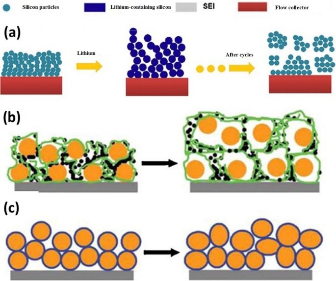
a Zeigt, wie die elektrische Beziehung von Nanopartikeln zum Stromkollektor unterbrochen wird, b zeigt eine andere Art der Trennung, Silizium-Nanopartikel in Orange und Kohlenstoff in Schwarz und PDVF-Polymerketten sind in Grün dargestellt. c Verwenden Sie amorphen Silikonkleber, um Nanopartikel auch nach Verformung zu verbinden [47].
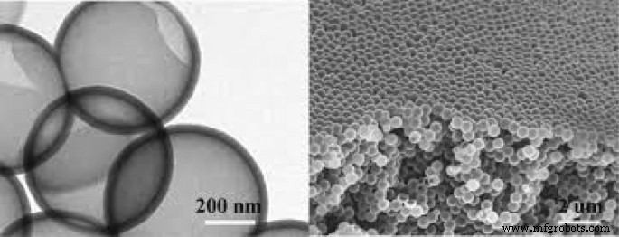
Hohle Nanopartikel zur Lösung des Volumenänderungsproblems [48]
Elektrolytzersetzung in der Anode
Wie wir wissen, ist jede Substanz in einem Potentialbereich stabil und unterliegt innerhalb dieses Bereichs mehr oder weniger einem Reduktions- oder Oxidationsprozess [28, 98, 99]. Deshalb können wir Wasser zersetzen (elektrolysieren), um Wasserstoff und Sauerstoff zu produzieren. Diese Zellen sind das Gegenteil von galvanischen Zellen (Batterien), sogenannten Elektrolytzellen. In diesen Zellen geben wir im Gegensatz zur Batterie Energie, um eine thermodynamisch nicht wünschenswerte Reaktion zu erzwingen [60].
Beim Aufladen der Batterie geben wir der Batterie wie beim Zersetzen von Wasser Energie über das Ladegerät, um die in der Batterie stattgefundene Reaktion umzukehren und die Batterie in ihren vorentladenen Zustand zurückzuführen [100,101,102,103,104]. Der in Lithium-Ionen-Batterien (z. B. Wasserelektrolyse) verwendete organische Elektrolyt verändert sich durch die Energie des Ladegeräts. Wie bereits erwähnt, findet bei einer Lithium-Ionen-Batterie am Minuspol (Graphitanode) während des Ladens eine Lithium-Ionen-Reduktion statt. Aufgrund der Tatsache, dass die Tendenz zur Elektrolytreduktion thermodynamisch höher ist als bei Lithiumionen, wird die Elektrolytreduktion anstelle der Lithiumionenreduktion durchgeführt. Dadurch bildet sich auf der Graphitoberfläche eine feste Schicht. Diese feste Schicht wird SEI (Solid Electrolyt Interface) genannt. Die Zusammensetzung dieser Schicht ist komplex und eine Mischung aus mehreren Chemikalien. Abbildung 10 zeigt eine schematische Darstellung dieser Ebene. Wie aus der Abbildung ersichtlich ist, enthält die Zusammensetzung dieser Substanz Lithiumionen und Kohlenstoff; daher geht die Bildung dieser Schicht mit einer Abnahme des Lithiums einher, was die Kapazität bei der ersten Ladung verringert [34, 61]. Diese Schichtdicke liegt im Nanometerbereich, wie in Abb. 10 gezeigt. Die Bildung der SEI-Schicht selbst begrenzt die Fortsetzung der Elektrolytreduktionsreaktion, da sie verhindert, dass die Elektrolytmoleküle die Graphitanodenoberfläche als physikalische Barriere erreichen. Tatsächlich wirkt es als kinetischer Inhibitor (wie die Passivschicht aus Aluminiumoxid, die verhindert, dass Sauerstoff das untere Aluminium erreicht und der Rest des Aluminiums oxidiert). Andererseits verhindert es, da es ein Elektronenisolator ist, auch, dass das Elektron den Elektrolyten erreicht [62,63,64,65]. Daher kann weder das Elektron das Elektrolytmolekül erreichen, noch kann sich das Elektrolytmolekül in Richtung des Elektrons in der Anode bewegen, was beides bewirkt, dass sich der Elektrolyt regeneriert und eine selbstbegrenzende Reaktion abläuft. Glücklicherweise ist diese Schicht für Lithiumionen durchlässig, und Lithiumionen können durch sie zur Anodenoberfläche gelangen, Elektronen einfangen und sich regenerieren [105,106,107,108]. Diese Schicht reduziert die Batterieleistung, da sie die Eindringstrecke des Lithium-Ions erhöht, um die Anode zu erreichen [109,110,111].
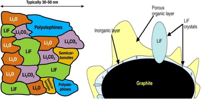
Schema der SEI-Bildung und Zusammensetzung dieser Schicht [66]
Abbildung 11 zeigt den Bereich der Elektrolytstabilität gegenüber dem Potenzial von Anoden und Kathoden. Weist die Kathode ein Potential über dem Elektrolytstabilitätsbereich auf, wird der Elektrolyt an der Kathode und beim Laden oxidiert, und auch wenn die Anode ein niedrigeres Potential als der Stabilitätsbereich hat, wird er an der Anode und während der Elektrolytladung regeneriert. Glücklicherweise haben konventionelle Kathoden, wie in Abb. 11 gezeigt, nicht das Problem der Elektrolytinstabilität, aber bei Graphit- und Siliziumanoden besteht Instabilität und es wird SEI gebildet [66,67,68].
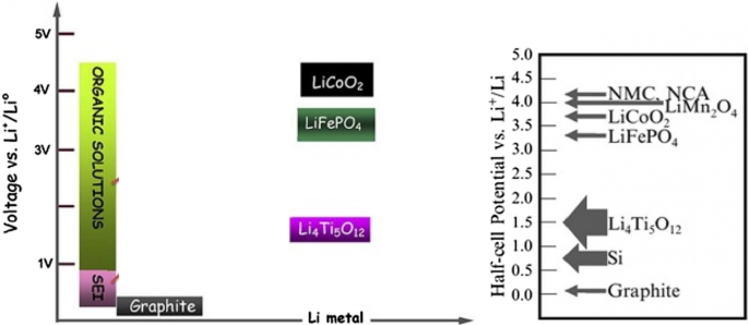
Zeigt die Spannung gemeinsamer Anoden und Kathoden und den Bereich des Elektrolytstabilitätspotentials und den Potentialbereich der SEI-Bildung [67]
SEI-Problem in Silizium
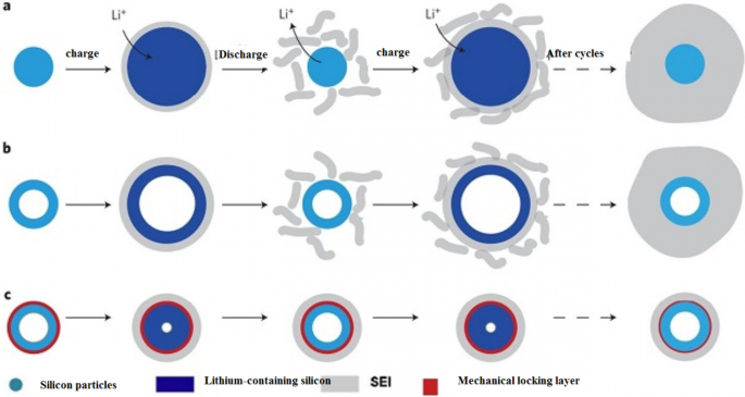
Im Allgemeinen ist der Elektrolyt bei Anoden mit weniger als einem Volt relativ zu Lithiummetall instabil und es wird SEI gebildet. Daher wird SEI in der Siliziumanode gebildet, die ein 0,3 bis 0,4 höheres Potenzial als Lithium hat [112, 113, 114, 115]. Da Silizium sein Volumen ändert und zerfällt, werden dem Elektrolyten leider neue Siliziummengen ausgesetzt, so dass das Elektron den Elektrolyten erreicht und auf diesen neuen Oberflächen ein neuer SEI gebildet wird. Dadurch wird die Kapazität während der Arbeitszyklen ständig reduziert. Dies muss erwähnt werden, da häufig an Lithium-Metall getestet wird, bei allen Batterieartikeln werden Spannungen relativ zu Lithium gemessen [69]. In Silizium-Nanomaterialien ist es aufgrund der höheren chemischen Aktivität noch anfälliger für die Bildung von SEI. Bei Nanomaterialien ist es richtig, dass sie nicht abgebaut werden, aber ihr Volumen verändern. Gemäß Abb. 12 führt diese Volumenänderung dazu, dass der SEI kontinuierlich wächst, und wir sehen die Nachteile des SEI-Wachstums, wie z. B. verringerte Kapazität und Leistung usw. Abbildung 13 von Abschnitt a veranschaulicht den Grund für das SEI-Wachstum bei Nanomaterialien besser. Wenn wir den Querschnitt eines Nanodrahts (oder Nanopartikel usw.) im Ausgangszustand ohne Lithium haben, der auf der linken Seite der Abbildung dargestellt ist, während des Ladens nimmt sein Volumen aufgrund des Lithiumgehalts des Siliziums und aufgrund des Elektrolyten zu Instabilität wird gleichzeitig eine SEI-Schicht auf dem Nanodraht gebildet [116,117,118,119]. Während der Entladung tritt nun das Lithium aus und das Partikel schrumpft, während das SEI nicht schrumpft. Dies führt dazu, dass der SEI unter Stress bröckelt (oder sogar in der zweiten Stufe der Siliziumvergrößerung unter Lithiumionisation, an welchem Punkt Stress auftritt und der SEI zerbröckelt, weil die genaue Grenze zwischen dem SEI und dem Partikel nicht genau übereinstimmt). Daher wird beim Wiederaufladen (Lithium-Ionisation) wieder eine neue SEI-Schicht gebildet. Die Wiederholung dieses Zyklus führt zu einem kontinuierlichen SEI-Wachstum, und wir haben Probleme mit seinem Wachstum, während SEI bei Graphit ohne eine geringfügige Änderung seines Volumens nicht wachsen würde. Es sollte beachtet werden, dass das, was über SEI und Silizium gesagt wurde, auch für andere Legierungsanoden gilt [70, 120, 121, 122, 123]. Wie in Abschnitt b gesehen, besteht dieses Problem auch für Silizium-Nanoröhren, aber wenn wir irgendwie verhindern können, dass das Silizium von Anfang an mit dem Elektrolyten in Kontakt kommt und sein Volumen in der Nähe des Elektrolyten ändert, ist dieses Problem gelöst.
Wie die SEI-Schicht wächst [19]
Zeigt das Wachstum von SEI unter verschiedenen Bedingungen [20]
Wuet al. [18] eine mechanische Sperrschicht verwendet, wie in Abb. 13c gezeigt; diese Schicht aus Siliziumoxid verhindert durch ihre mechanische Festigkeit die Veränderung des Außenvolumens der Nanoröhren. Somit wird eine stabile SEI ohne Volumenänderung gebildet (eine stabile SEI-Schicht wie Graphit). Diese Oxidschicht ist der Leiter von Lithiumionen, so dass sie keine Probleme mit der Reaktion verursacht. Der notwendige Raum zur Volumenänderung wird auch durch die Innenwand der Nanoröhre bereitgestellt. Es gibt also kein Quetschproblem. Da die Studie zeigte, dass der Elektrolyt nicht in die Nanoröhre eindringt, besteht kein Kontakt zwischen dem Elektrolyten und der Innenwand der Nanoröhre. All diese Vorteile sorgen für eine lange Lebensdauer und gute Leistung. Abbildung 14 (in dieser Abbildung mit DWSiNT gezeigt) zeigt einen Teil der Tiefentladungszyklen dieser Probe. Bei Tiefentladung reduziert sich die Zyklenlebensdauer immer schneller. Es wird jedoch beobachtet, dass die präparierte Probe nach 900 Zyklen immer noch eine gute Kapazität aufweist, die normalen Nanoröhren- und Nanodrahtproben jedoch schnell ihre Kapazität verlieren. Entladen) Für die aufgetragene Probe zeigt sich, dass die Kapazität ihre Kapazität auch nach dieser relativ hohen C-Rate selbst bei bis zu 6000 offenen Zyklen beibehält. In einem anderen Beispiel [19] wird eine Kern-Schale-Struktur hergestellt, wie in Abb. 15c gezeigt, eine Kohlenstoffbeschichtung wird mit Siliziumnanopartikeln innerhalb der Kohlenstoffbeschichtung verwendet. Die Dicke der Kohlenstoffbeschichtung liegt im Bereich von 10 nm und enthält 100 nm große Siliziumpartikel. Die Kohlenstoffhülle bietet ausreichend Platz, um das Volumen des Silizium-Nanopartikels leicht zu verändern, wie in Abbildung c gezeigt. Auf der anderen Seite werden Silizium-Nanopartikel von einem Punkt an die Kohlenstoffhülle angelagert, sodass darin Elektronen- und Ionenübergänge stattfinden, da sich Kohlenstoff in der Nähe des Elektrolyten befindet und nicht Silizium, wie Graphit, wird ein stabiler SEI ohne Zerkleinerung gebildet da die Volumenänderung von Silizium nicht auf Kohlenstoff und von Kohlenstoff auf SEI übertragen wird, ähnlich der Abbildung in Abb. 12, hat es eine lange Lebensdauer. Wenn wir normalerweise Silizium-Nanopartikel verwenden, zeigt dies zusätzlich zum SEI-Problem, wie wir im vorherigen Artikel und in Abbildung a gesehen haben, dass es keinen leeren Raum zwischen den Silizium-Nanopartikeln gibt, um das Volumen zu ändern, also gibt es Spannungen zwischen den Partikeln, wenn sie ändern ihr Volumen, aber bei Verwendung dieser Hohlstruktur (Abbildung b) gibt es keine Spannung mehr zwischen den Partikeln.
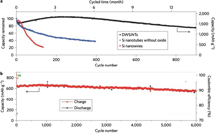
a Vergleich der Zyklenlebensdauer von Schwarz, Blau und Rot für oxidbeschichtete, b oxidfreie bzw. nichtoxidfreie Nanoröhren [21]
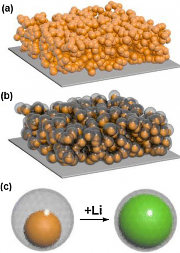
a Darstellung von Elektroden aus Silizium-Nanopartikeln. b Elektrodendisplay aus Silizium-Nanopartikeln mit Kohlenstoffbeschichtung und Hohlstruktur. c Die Struktur der Kern-Hohlschale in b , das Silizium befindet sich im Inneren des hohlen Kohlenstoffs und seine Volumenänderung wird während der Lithiumionisation beobachtet [10]
Diese Anode hat neben dem SEI-Problem im Vergleich zur Probe in Abb. 12 weitere Vorteile. Ein Vorteil der Nanopartikelsynthese gegenüber Nanoröhrchen und, noch wichtiger, die Verwendung von Nanopartikeln im Vergleich zu Nanodrähten, ist gut mit der Slurry-Methode kompatibel. Dies ist die herkömmliche Methode zur Vorbereitung von Elektroden in Batterien.
Einführung der LTO Anode
Bisher haben wir über zwei Arten von Graphitanoden und Legierungsanoden (Silizium) gesprochen. Eine weitere sehr beliebte Anode ist die Anode mit Li4Ti5O12-Verbindung, die kurz LTO genannt wird. Diese Anode ist wie Interkalationsgraphit [29, 124,125,126,127]. Abbildung 16 zeigt den Aufbau und die Reaktion dieses Anodentyps. Die LTO-Anode hat eine begrenzte Kapazität von 175 mAh/g (im Vergleich zu 300 Graphit und 4000 Silizium). Die Spannung dieser Anode beträgt ebenfalls etwa 1,5 V im Vergleich zu Lithiummetall gemäß Abb. 17 (je niedriger die Anodenspannung, desto höher die Batteriespannung). This high voltage and low capacity both make this anode have very low energy, but it is still one step ahead of silicon in commercial terms. One of the most important features of this anode is the safety issue, because in electric vehicles there are unpredictable conditions, and the other is the long cycle life, and finally its power [72, 73, 128,129,130].
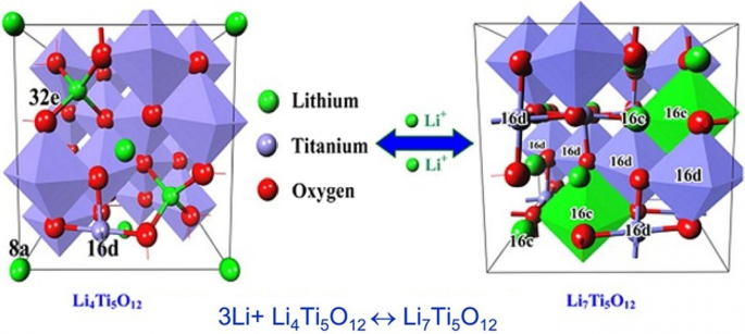
Shows the structure and entry of lithium ion in LTO along with its reaction [74]
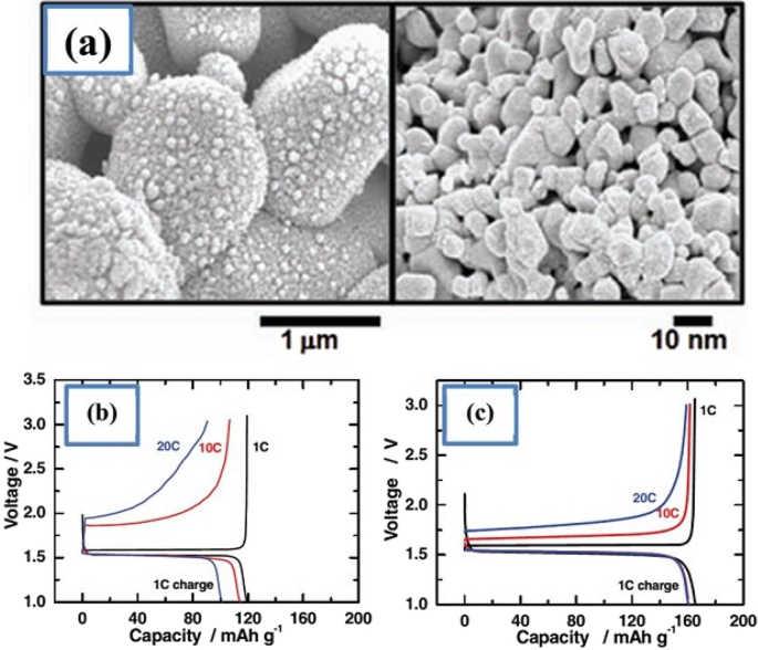
a Displays the nanostructure discussed including Nano primary nanoparticles, b charge–discharge curve for ordinary micro particles, and c for a-shaped particles [74]
Due to the fact that the voltage of this anode is high, it is in the range of electrolyte stability according to Fig. 17, so SEI is not formed. On the other hand, as shown in Fig. 17, there is enough space for lithium ions in this composition and it does not change volume, while even in graphite, some volume change is seen due to the entry and exit of lithium. Unlike the previous two anodes, lithium ions (not lithium atoms) are stored in this anode, and the oxidation reaction is due to the conversion of titanium to 3-valent titanium, not to a change in lithium capacity [28, 74, 75, 131].
This battery, because it has neither SEI nor volume change, maintains the capacity well and has a very long cycle life (more than graphite) of about 20,000 cycles. Because it is an oxide compound and is very safe due to the lack of volume change. Because it does not have SEI, its power is not bad either, only its lithium ion diffusion coefficient is low and its electron conductivity is poor. To solve this problem, they provide LTO nanostructures. Because this anode did not have SEI from the beginning, when it becomes Nano, it does not have the problem of forming more SEI, so it does not have more nanomaterial activity [32, 35,36,37].
It has been observed that nanoparticles cause the LTO anode to charge and discharge within 5 min (12C). To prepare the nanostructure, first titanium oxide nanostructure is prepared and then reacted with a lithium source material when heated. This is also an advantage of LTO, as the preparation of TiO2 nanostructures is very popular. Due to the problem of low volumetric density and agglomeration of nanomaterials, micron secondary particles made from nanoscale primary particles are more useful [33, 38, 58, 59].
Figure 17 shows part an of this nanostructure. As can be seen, from the controlled community of smaller particles measuring 10 nm, larger micron particles are formed. According to the comparison of parts b and c in Fig. 17, it is quite clear that this nanostructure is superior to ordinary micron particles, because it has less capacity and potential (especially in discharge). From this nanostructured anode, a battery is made and it is observed that this battery is superior to the battery with graphite anode both in terms of cycle life and power, which is not given due to the brevity of these curves [75]. The benefits of Nano-LTO have been well documented in many articles, but what makes it stand out is an important discussion of proper engineering of the structure, proper synthesis method, and how to use the conductive material to improve conductivity for further improvement. The future will be talked about. In addition, it is not disputed that nanotechnology is useful for LTO, but many of the phenomena that occur at the nanoscale for LTO are discussed so that some are not fully understood.
Another phenomenon that occurs at the nanoscale is the change in charge–discharge curves for the LTO anode. This anode provides a constant voltage over a wide range of capacities (red box in Fig. 18). When LTO ions are Nano, the constant voltage range decreases until after a critical limit (in the range of a few nanometers) there is no longer a constant voltage range [76].
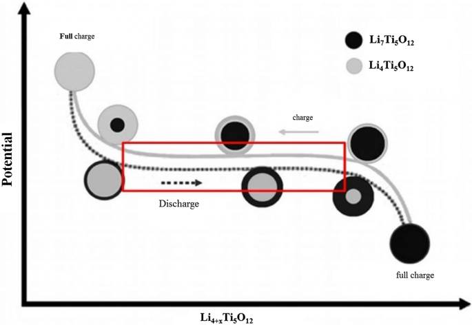
Shows the linear curve range at the LTO anode in the charge–discharge axis [75]
One of the things that happens on the surface is the insertion of more lithium ions into the surface layers. In the surface after insertion, we reach the formula Li8.5 Ti5 O12 , which is 1.5 mol more than the inner layers with the formula Li7 Ti5 O1 , but in the micron material, because the percentage of surface is not high, it shows its effect, but for Nano, because the amount of surface is large, the effects are large. There are several on the charge–discharge curve.
TiO2 Anode
There is also a TiO2 anode from the LTO family. These anodes are easier to synthesize, and because they do not want to react with heat-induced lithium ion precursors, they do not have heat-induced problems such as nanomaterial growth. In addition, according to the chemical formula, titanium oxide has a capacity of twice the amount of 335 mAh/g (LTO). The general response of these anodes is \({\text{TiO}}_{2} + x{\text{Li}}^{ + } + xe^{ - } \leftrightarrow {\text{Li}}_{x} {\text{TiO}}_{2} .\)
TiO2 has four types of phases or crystallographic structures (different atomic arrangements) known as Brocket, Anastasi, Rutile, and (TiO2 (B). The Brocket phase does not matter to the battery. Antara and rutile, which are very popular phases, are important as anodes. Phase (TiO2 (B) performs better than others due to its atomic open space and suitable channel for ion transport, and is the most important [75, 76, 132,133,134,135,136].
If we consider the theoretical capacity based on the chemical formula (one mole of lithium ion per mole of TiO2 ), it is equal to the above value, but based on the phase and position that can be placed according to the lithium ion crystal lattice, different theoretical capacities for different phases have been reported; for example, for anisate, according to network sites, the half-capacity is high, 0.5 mol of lithium ion per mole of TiO2 , 167 mAh/g.
Because all of these phases have poor ionic conductivity, the nanoscale is very effective in increasing both power and capacity. What is interesting is that the nanostructured capacity of Anastasi is more than the theoretical capacity based on the position of the network, but it is definitely less than the theoretical capacity of Formula 334 in all phases. Rutile in micron mode can only store 0.1 mol of lithium ion per grid unit. In rutile, lithium locations are located throughout the network, but the diffusion coefficient in the direction of the c -axis is one order of magnitude greater than that of the ab plate [137,138,139,140,141]. The lithium atom penetrates well in the direction of the c -axis, but must be diffused throughout the space by penetrating the ab plane, and because the diffusion velocity is low in the ab plane, lithium ions accumulate in the c channel, causing a charge repulsive force. Lithium ion positive is generated. This repulsive force prevents more ions from entering the network. As an interesting result of the Nano effect, it has been shown that when the dimensions of rutile become Nano, the capacity reaches 0.8 mol of lithium ion, which has a reversible capacity during different cycles, which reduces the penetration distance and the effect of its quadratic power [142,143,144,145,146]. There is no repulsive force. Figure 19 shows the charge and discharge curves and the cycle life for rutile bulk (micron), commercial rutile micro particles, and rutile nanowires. As can be seen, nanowires show good cyclic longevity and capacity. The shape also confirms that the shape of the nanomaterials also affects the performance of the anode. Morphology such as nanoparticles, nanowires, etc. differ in both capacity and life cycle and power, but the type of morphology alone is not decisive but the geometry of the structure that determines the performance (in the future about the geometry of the structure for all active materials for example, nanowires connected to a current collector, nanowires mixed with graphene, and insulated nanowires each present different results. In addition, there are test conditions and C rate and many other factors [77]. Phase (TiO2 (B), which is newer than other phases, offers the best power and capacity due to its suitable channels for lithium ion transport [147,148,149,150,151]. Figure 20 shows the structure of the penetration site. The capacitance can be significantly increased. This phase offers the best power and capacity among all titanium anodes including LTO, so that by Nano partying it in just 4.5 s, the anode can be charged or discharged with a capacity of 73% of theory. We do not have volume change in this anode either.
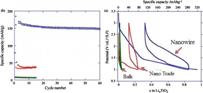
a Charge–discharge curve for the first time, b cycle life [77].
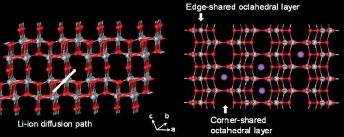
Showing the atomic structure of the phase (TiO2 (B) [77]
Quasi-capacitive Capacity
So far, it has been discussed about the storage capacity of lithium ions in the form of a degree in the nuclear network, and this capacity is improved in the nanoscale due to the reduction of the penetration distance, and so on [152,153,154,155]. But one of the interesting phenomena that occurs for these anodes at the nanoscale is the storage of lithium ions at the surface due to the large surface-to-volume ratio. This type of storage is different from the insert and alloy capacity mentioned so far. This type of storage is very fast because it does not require penetration, and also because it does not create stress and the like, it has the best cycle life and power compared to other lithium storage methods [156,157,158]. Of course, this type of capacity generates less energy. This capacity is discussed in more detail in the topic of super capacitors. The Fig. 21 shows a comparison between the storage capacity of LTO capacity in three different Nano dimensions [78]. According to Fig. 21 in small Nano dimensions, this capacity is significant and decreases significantly with increasing dimensions. It should be noted that capacitive capacitance is not only related to titanium oxide compounds but is also present in many other active substances that are mentioned when introducing them.
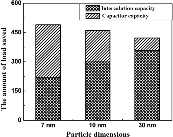
Demonstration of input and super capacitor capacities in titanium oxide [78]
Introduction of Exchange Anodes
So far, we have talked about two types of insert electrodes and alloys. The third type of electrode operation is based on a conversion reaction. Figure 22 shows the mechanism and reaction of this type of electrode. In this form, M (or Me) is an intermediate element that is oxidized, and X is an anion such as oxygen, sulfur, and the like [159,160,161]. The advantage of these anodes is that for every MxXy unit, n lithium ions (n more than one) are involved in the reaction, whereas in the graphite insert anodes we see one lithium ion for every 6 carbon atoms stored in titanium compounds. A maximum of one lithium ion is stored per TiO2 formula unit. But in the exchange anode, for example, for CoO and FeO, the value of n is equal to 2, and in Co3 O4 , the value of n is equal to 8. Figure 23 shows a number of exchangeable oxide anodes with their reaction and capacity [22, 30, 55].
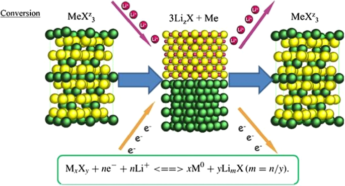
Shows the structure and entry of lithium ion with its reaction [22]

Shows the reaction and capacity of a number of conversion oxide anodes [30, 55]
Exchange Anode Problems
Exchange anodes are very similar to alloy anodes, as alloys have problems with volume change, fragmentation, and SEI formation. In these anodes the ionic and electron conduction is low, and in addition the exchange rate is slow. This low speed leads to high potential during charging and discharging. At these potentials, there is a large difference between the charging and discharging voltages, called hysteresis, which is shown in Fig. 24 with a red arrow. This figure shows that in the first stage of lithium extraction, the anode behavior is significantly different from the next stage of charge and discharge. The hysteresis in this type of anode is up to one volt, while in the graphite and LTO anode it is about 0.2 V. This hysteresis is mostly due to activation polarization [78, 79].
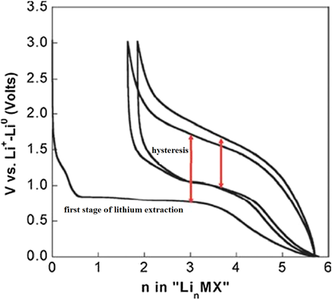
Show charge–discharge curves of exchange anodes [79]
Nano Sizing Effects
Figure 25 shows the lithium ionization behavior (in the test mode, against lithium metal) for anodes made of fine nanoparticles (20 nm) and micro-nanoparticles (500 nm) of iron oxide (SEM) images of these particles in Fig. 26. Available it can be seen that the capacity of the Nano anode is slightly higher. More importantly, it can be seen that the charge–discharge behavior of these two anodes is very different from each other, which is examined in Fig. 26. Figure 26 shows the charge–discharge curves in different cycles as well as the cycle life for the same samples in Fig. 25 to determine the reason for the difference in charge–discharge curves in Fig. 25. Note that instead of capacity, lithium that enters and leaves (which, according to the arguments, represents capacity) is used. In the charge–discharge curves of Fig. 26, lithium ionization continued only up to 1 mol because its purpose was to investigate the behavior in this range of lithium ions. As can be seen, the effective surface mass for the material is only 2 m 2 /g while for the Nano it has an effective surface area of 60 m 2 /g, which indicates how much higher the effective surface area is at the Nano. The difference between Nano and Nano performance is also quite clear. As shown in Fig. 26, the amount of reversible lithium (which can be removed during charging) for Nano is much higher than the corresponding amount for bulk. This shows that the capacity that can be recovered after the initial charge is much better in Nano than in micro. Also, according to the same figure, in the next consecutive charge-discharges, the amount of lithium entering and leaving is less than 0.25 (from 0.75 to 1), while for Nano, the amount of lithium entering and leaving is more than 0.5 (the amount of lithium ion). In the composition it has changed from the range of less than 0.5 ions to 1 ion), according to this, the capacity offered in Nano is much more than bulk. In the micron-sized anode of Fe2 O3 (hematite), before the exchange reaction begins, about 0.1 mol of lithium ion per mole of oxide compound can be stored in the lattice, but above this critical limit, the exchange reaction takes place; on the other hand, when we increase the dimensions of iron oxide particles to 20 nm, the amount of lithium stored in degrees reaches 1 mol, which causes a volume change of only about 1%. Of course, about 0.5 mol is reversible (Fig. 25). In fact, the type of storage mechanism (input, exchange, etc.) changes and the type of mechanism affects the shape of the charge–discharge curve. The above paragraph indicates that when the oxide dimensions enter the Nano field, the storage mechanism is also affected. So far it has been said that Nano makes volume change easier without failure, but here it can be seen that even Nano has reduced the amount of volume change from a few percent for the exchange reaction to one percent for a degree reaction. The reason for this change is the storage mechanism for iron oxide due to thermodynamic problems. The opposite happens for the Co3 O4 anode because it is kinetic and is related to the current density (the current density is obtained by dividing the current by the surface); when the current is constant, in the Nano-dimensions, because the surface is higher, the current density decreases and the Co3 O4 anode shows exchange behavior, but in the micro, due to the high current density, the anode shows the insertion behavior [76,77,78,79].
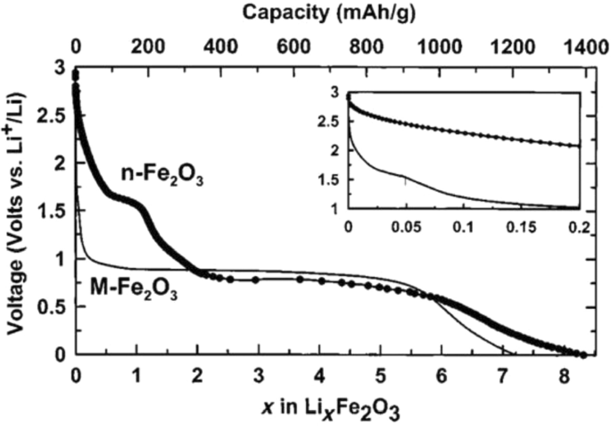
Demonstration of lithium ionization for n -Fe2 O3 and micro-M-Fe2 O3 [80]
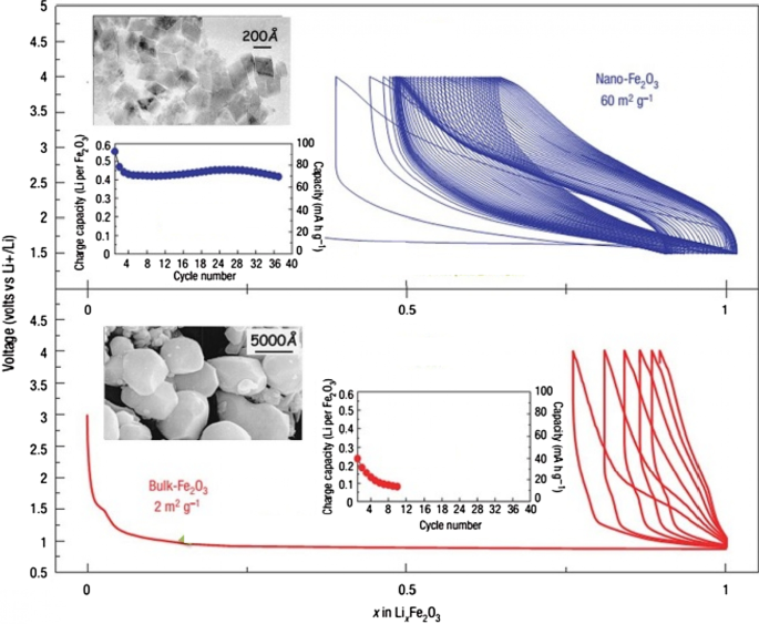
Display of SEM images, charge–discharge curves and cycle life for Nano-iron oxide and bulk [80]
It can be seen from Fig. 26 that at the nanoscale, the cycle life is also much better than bulk. The reason for the improvement of these expressed properties is the ease of volume change and release of stress, ionic and electronic transitions are easier due to the reduction of the penetration distance, which was expressed in this series of articles. Due to high hysteresis, less attention has been paid to compounds with hysteresis [22, 51,52,53,54, 80].
Nanomaterials in Batteries
Nanomaterials have been widely applied in the life sciences, information technology, the environment, and other related fields. Recently, nanostructured materials have also attracted attention for application in energy storage devices, especially for those with high charge/discharge current rates such as lithium ion batteries. The development of next-generation energy storage devices with high power and high energy density is key to the success of electric and hybrid electric vehicles (EVs and HEVs, respectively), which are expected to at least partially replace conventional vehicles and help solve the problems of air pollution and climate change. These energy storage technologies will rely on innovative materials science, i.e. developing electrode materials capable of being charged and discharged at high current rates. Generally, the potential advantages of nanostructured active electrode materials can be summarized as follows:new reactions can be used that are not possible with bulk materials; a larger electrode/electrolyte contact area, leading to higher charge/discharge rates; short path lengths for both electronic and Li ion transport (permitting operation even with low electronic or low Li ion conductivity, or at higher power); etc. Here, we review some recent experimental results that show the advantages of nanostructured active electrode materials [147]. Table 2 summarizes the nanotechnologies that are used to produce nanomaterials, such as mechanical ball milling, chemical vapour deposition, the template method, electrochemical deposition, hydrothermal reaction, dehydration, sintering, pulsed laser deposition, ultrasound, sol–gel synthesis, and micro emulsion.
The first group of applications of nanotechnology in batteries is itself divided into two categories:the first group nanoscale the active substance in the electrode, the second group use nanotechnology to improve the performance of electrodes (cathode or anode) by adding nanomaterials other than the active substance, or the use of Nano coatings. For example, Nano-dimensional additives such as Nano carbons, graphene, carbon nanotubes, etc. have better electron conduction, or the use of Nano-thick coatings on the active material to prevent unwanted reactions with the electrolyte, stress modulation, provide stability and …. for it. For example, for a LiFePO4 cathode, the amount of electron conductivity is poor. Conductivity is improved by using a conductive carbon coating on its particles or by using a conductive carbon material as an additive, A Nano-thick coating of oxide is used [83, 94, 172,173,174,175,176,177]. For example, for a LiFePO4 cathode, the amount of electron conduction is poor, Conductivity is improved by using a conductive carbon coating on its particles or by using a conductive carbon material as an additive, or the LiCoO2 cathode is unstable at high currents in the vicinity of the electrolyte, using a Nano-thick oxide coating to stabilize it [162, 163, 178, 179]. If we want to illustrate the field of nanotechnology in this category with an example, in the same LiFePO4 cathode it has been shown that carbon coating increases conductivity and consequently power, capacity, etc., but one of the areas of research is how to create this coating. Be cheap, effective, etc.; therefore, research in the field of synthesis methods is very important. On the other hand, how to add the same coating and additives to be more effective, so the engineering and architecture of nanostructures is one of the important areas of research and the preparation of these engineered structures is also an interesting issue. Consider Fig. 27 to clarify the matter. This figure shows two types of Nano-engineered structures for the LiFePO4 cathode that use carbon nanotubes to improve conductivity. In addition to differences in performance, each of these structures has a different synthesis method, which indicates the importance of synthesis.
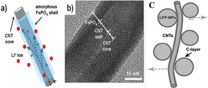
a , b With carbon nanotube core and LiFePO4 wall, and Figure c LiFePO4 nanoparticles attached to carbon nanotube [3, 93]
Silicon has attracted tremendous attentions as one of the most promising candidates for the next-generation Li-ion batteries (LIBs). Compared to the traditional graphite anode, it has many obvious advantages such as large capacity, high abundance and environmental friendliness [1,2,3,4]. Unfortunately, due to the huge volume expansion (~ 300%) in lithiation, silicon particles are pulverized and solid electrolyte interphase (SEI) layers formed on their surface are unstable. Therefore, the long-term cycling stability of silicon anode is poor [5,6,7,8]. Moreover, the low intrinsic conductivity of Si causes unsatisfying rate-capability [9,10,11,12]. Thus, a large amount of Si/metal (e.g., Ag, Cu, Al, Sn) composites have been developed to solve the low conductivity [13,14,15,16]. However, the large volume expansion cannot be relieved effectively. On the other hand, carbon Nano layers are coated on the electrode materials to increase their conductivity, enhance their mechanical strength and provide them stable interfaces with electrolyte. Therefore, various conformal carbon layer coated silicon (Si@C) nanostructures are developed. For example, Si@C with core–shell structure are formed by pyrolyzing various precursors (e.g., pitch, glucose) to coat carbon layers on the pre-prepared silicon nanoparticles [17,18,19,20,21].
Cui et al. designed a hierarchical pomegranate-structured Si@C composite and a nonfilling carbon-coated porous silicon micro particle via the pyrolysis of resorcinol–formaldehyde resin (RF), respectively [23, 82]. And Yu et al. prepared double carbon shells coated Si nanoparticles via chemical vapor deposition (CVD), with acetylene as carbon source [24]. All these designs provide sufficient voids to allow large volume changes of Si during the lithiation/delithiation. However, most of Si@C composites were prepared in separate steps by either pre-coating or post coating carbon on silicon nanomaterials. It led to a complicated preparation strategy.
Continued interest in high performance lithium-ion batteries has driven the development of new electrode materials and their synthesis techniques, often targeting scalable production of high quality nanoceramics (< 100 nm in diameter), which may offer performance improvements. However, there are a number of hurdles, which need to be overcome to move away from current batch synthesis methods that offer poor reproducibility or lack of control over crystallite attributes, particularly at larger scale syntheses. Continuous hydrothermal flow synthesis (CHFS) processes are a promising route for the direct and controlled manufacture of Li-ion battery electrode nanoceramics. Such processes use superheated water and metal salt mixtures as reagents. In a typical CHFS reaction, a feed of supercritical water (above the critical point of water (TC = 374 °C and Pc = 22.1 MPa), is rapidly mixed in an engineered mixer [1] with a metal salt/base aqueous precursor feed (at ambient temperature and the same pressure), resulting in rapid formation of the corresponding nanocrystallite oxide in the water. This nucleation dominated reaction occurs as a result of the metal salts being supersaturated upon mixing with sc-water and also instantly being hydrolysed and dehydrated under these exotic reaction conditions. The nascent nanocrystallite metal oxide stream in water is then cooled in process and then can be constantly collected from the exit of the CHFS process as an aqueous nanoparticle slurry at ambient temperature. The cleaned crystallites (e.g. via dialysis) can be obtained as a wet solid and then freeze-dried to retain maximum surface area and reduce agglomeration. Compared to batch hydrothermal syntheses, CHFS type processes typically produce very small nanoparticles (< 10 nm) with a narrow size distribution [2,3,4]. Additionally, CHFS processes are highly scalable (> 1 kg per hour in the lab of the UCL authors [5]) and can be used to make high quality nanoparticles at scale, with little or no significant variation between those made on the smaller CHFS laboratory scale process.
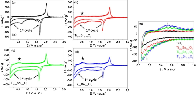
Cyclic voltammetry (CV) measurements at a scan rate of 0.05 mV s −1 in the range of 0.05–3 V versus Li/Li + , are presented in Fig. 28. A pair of cathodic and anodic peaks were observed in the potential range 1.5 and 2.3 V versus Li/Li + , relating to Li-ion insertion into and extraction from the interstitial octahedral site of TiO2 (see equation) [81]. Under normal circumstances, a two-phase reaction is expected to occur during lithiation with phase equilibrium of the Li-poor Li0.01 TiO2 (tetragonal) phase and the Li-rich Li0.55 TiO2 (orthorhombic) phase [19, 20]. The detected specific current peak decreased with higher amount of Sn, thereby reducing the amount of pure TiO2 . The pure TiO2 sample showed virtually no electrochemical activity in the potential range between 1.3 and 1 V versus Li/Li + during the first cycle. The increasing specific current during the first cycle between 1 and 0.05 V versus Li/Li + , is attributed to solid electrolyte interface (SEI) formation (electrolyte destruction) at lower potentials [13]. There was also likely to be substantive SEI formation at the crystallite surfaces of the Sn-doped materials compared to the undoped TiO2 , as there was significant electrochemical activity in the range of 1.3 to 1 V versus Li/Li + for the former. However, as the surface area decreases with higher Sn-loading, the initial capacity loss due to the SEI formation may be expected to decrease. The general trend in fact showed that with higher Sn-loading, the initial irreversible capacity loss increased (from 363 mAh g −1 for the pure TiO2 and 467 mAh g −1 for Ti0.85 Sn0.15 O2 ).

Cyclic voltammograms for the 1st and 2nd cycles for the as-prepared Nano-powder in the potential range of 0.05 and 3 V versus Li/Li + for an applied scan rate of 0.05 mV s −1 for a undoped anatase TiO2 , b Ti0.94 Sn0.06 O2 , c Ti0.89 Sn0.11 O2 , and d Ti0.85 Sn0.15 O2 . e Specific current versus potential of the 2nd cycle for all materials at lower potentials. The specific current was calculated by taking into account the active material mass loadings [81]
Conclusion
- 1.
This article discusses silicon anodes as a representative of alloy anodes. It was observed that the only solution to solve the shredding problem is to use nanotechnology. In this paper, the importance of nanomaterial synthesis was expressed. In summary, how to use nanomaterials with different morphologies to solve the problem and improve power. Although various morphologies were discussed, there was no discussion of structural engineering and the use of carbon conductive materials, which will be discussed in future articles. This was one of the methods of establishing electrical bonding for nanoparticles. There are various structures to prevent the nanoparticles from breaking, the art of which is to create different geometries and the method of their preparation.
- 2.
This article discusses SEI, which is one of the most important topics in most anodes and some high voltage cathodes. This article discussed the problem of alloy anode fragmentation, while which is due to the continuous growth of SEI. It turned out that in order to have a proper cycle life, this problem must be overcome. According to the given examples, using a suitable design at the nanoscale, in addition to providing free volume change of silicon, this volume change does not occur in contact with the electrolyte.
- 3.
The carbon coating on the anode can increase the conductivity from 13–110 to 2.05 S/cm. Doping can enhance performance by increasing the conductivity of electrons and even ions and providing more space within the network along with Nano sizing, which may be appropriate for new projects, which is more a Nano-topic in Nano synthesis than how it accompanies matter. Synthesize with Nano-dimensional doping until there is a discussion about the effect of Nano on improving anode performance. This article discusses titanium oxide anodes, which is one of the most commercially important anodes. It was found that nanotechnology greatly improves the performance of these anodes. Nano sizing has also been shown to affect even the electrochemical and chemical-physical nature (such as charge–discharge curve deformation and greater capacity in surface layers).
- 4.
In this paper, exchange anodes are introduced and their complex operation is described. It was found that many problems, such as alloy anodes, can be solved by Nano damaging the active material. The special effects of Nano were expressed as a change in mechanism.
Availability of Data and Materials
All data generated or analyzed during this study are included in this published article.
Nanomaterialien
- Überprüfung von R, X und Z (Widerstand, Reaktanz und Impedanz)
- Zuverlässigkeit und schlanke Programme Power Energizer Batterieanlage
- Zinn-Nanokristalle für zukünftige Batterien
- Eine Übersicht über die Anwendung von Biosensoren und Nanosensoren in Agrarökosystemen
- Graphen- und Polymerverbundstoffe für Superkondensatoranwendungen:ein Rückblick
- Hydrothermal-unterstützte Sinterstrategie für poröses und hohlstrukturiertes LiNb3O8-Anodenmaterial
- Umwandlung von Schlamm-Si in Nano-Si/SiOx-Struktur durch Sauerstoffeindringung als Vorläufer für Hochleistungsanoden in Lithium-Ionen-Batterien
- Übersicht:Poröse Metallfilter und Membranen für die Öl-Wasser-Trennung
- 4 Gründe, warum Lithiumbatterien besser sind als Bleibatterien
- Roboter und Batterieherstellung:Eine positive Verbindung


