Resistive Random Access Memory (RRAM):ein Überblick über Materialien, Schaltmechanismen, Leistung, Multilevel Cell (mlc)-Speicherung, Modellierung und Anwendungen
Zusammenfassung
In diesem Manuskript werden die jüngsten Fortschritte auf dem Gebiet der resistiven Direktzugriffsspeicher (RRAM)-Technologie, die aufgrund ihrer hohen Geschwindigkeit, geringen Kosten, verbesserten Speicherdichte, potenzieller Anwendungen in verschiedenen Bereichen und hervorragenden Skalierbarkeit wird umfassend überprüft. Zunächst wird ein kurzer Überblick über das Gebiet der neuen Speichertechnologien gegeben. Die Materialeigenschaften, der Widerstandsschaltmechanismus und die elektrischen Eigenschaften von RRAM werden diskutiert. Außerdem werden verschiedene Aspekte wie Lebensdauer, Retention, Gleichmäßigkeit und der Einfluss von Betriebstemperatur und zufälligem Telegraphenrauschen (RTN) erläutert. Es wird eine Diskussion über die Multilevel-Cell-(MLC)-Speicherfähigkeit von RRAM präsentiert, die attraktiv ist, um eine erhöhte Speicherdichte und niedrige Kosten zu erreichen. Es wurden verschiedene Betriebsschemata bereitgestellt, um einen zuverlässigen MLC-Betrieb zusammen mit ihren physikalischen Mechanismen zu erreichen. Darüber hinaus wird in dieser Arbeit eine ausführliche Beschreibung von Schaltmethoden und Stromspannungsbeziehungen für verschiedene gängige RRAM-Modelle behandelt. Die voraussichtlichen Anwendungen von RRAM in verschiedenen Bereichen wie Sicherheit, neuromorphes Computing und nichtflüchtige Logiksysteme werden kurz angesprochen. Der vorliegende Übersichtsartikel schließt mit der Diskussion über die Herausforderungen und Zukunftsaussichten des RRAM.
Einführung
Direktzugriffsspeicher, der als RAM bezeichnet wird, kann entweder flüchtig oder nichtflüchtig sein. Ein flüchtiger Speicher verliert seine zuvor gespeicherten Daten beim Entfernen der Stromversorgung, wie dies bei einem dynamischen Speicher mit wahlfreiem Zugriff (DRAM) und einem statischen Speicher mit wahlfreiem Zugriff (SRAM) der Fall ist. Bei nichtflüchtigen Speichern bleiben die zuvor gespeicherten Inhalte auch nach dem Entfernen der Versorgung erhalten. Flash-Speicher ist ein typisches Beispiel für nichtflüchtigen Speicher. Speichertechnologien kombinieren die Vor- und Nachteile, um eine höhere Leistung zu erzielen, z.B. DRAMs, die in einem Computersystem verwendet werden, haben eine hohe Kapazität und Dichte, aber sie sind flüchtig, was bedeutet, dass alle paar Millisekunden aufgefrischt werden müssen. Durch diese Auffrischung erhöht sich der Energieverbrauch des Geräts, was nicht erwünscht ist. SRAM hingegen ist schnell, aber ebenso flüchtig wie der DRAM; außerdem sind SRAM-Zellen größer, was ihre Implementierung in großem Maßstab behindert. Flash-Speicher, der im Wesentlichen aus einem Metall-Oxid-Halbleiter-Feldeffekttransistor (MOSFET) sowie einem Floating-Gate in jeder Speicherzelle besteht, wird derzeit aufgrund seiner geringen Kosten und hohen Dichte insbesondere für Embedded-Anwendungen intensiv eingesetzt . Abhängig davon, wie Speicherzellen organisiert sind, wird Flash-Speicher als NOR-Flash und NAND-Flash klassifiziert [1]. Beim NOR-Flash werden Zellen einzeln gelesen und programmiert, da sie parallel zu Bitleitungen geschaltet sind. Dies ähnelt der Parallelschaltung von Transistoren in einer CMOS-NOR-Gate-Architektur. Im Fall von NAND-Flash ähnelt die Architektur der eines CMOS-NAND-Gatters, da die Zellen in Reihe mit den Bitleitungen verbunden sind. Es muss beachtet werden, dass die Reihenschaltung weniger Platz verbraucht als die parallele, was zu geringeren Kosten für NAND-Flash führt. Beide Arten von Flash-Speichern haben jedoch mehrere Nachteile, wie z Schreib-/Löschzyklen) und hohe Schreibspannung (> 10 V) [2].
Die oben erwähnten Speichertechnologien, d. h. DRAM, SRAM und Flash, sind ladungsspeicherbasierte Speicher. DRAM speichert die Informationen in Form von Ladung am Kondensator, und SRAM basiert auf der Speicherung von Ladung an den Knoten der kreuzgekoppelten Inverter, während die Flash-Speichertechnologie das Floating-Gate des Transistors verwendet, um die Ladung zu speichern. Alle diese bestehenden ladungsspeicherbasierten Speichertechnologien stehen derzeit vor der Herausforderung, auf 10 nm Knoten oder darüber hinaus zu skalieren. Dies wird dem Verlust gespeicherter Ladung im Nanobereich zugeschrieben, der zu einer Verschlechterung der Leistung, Zuverlässigkeit und Rauschspanne führt. Darüber hinaus stellen die Anforderungen an eine große dynamische Auffrischleistung für DRAM und Leckleistung sowohl für SRAM als auch DRAM ernsthafte Herausforderungen für das Design der zukünftigen Speicherhierarchie dar.
Daher befindet sich derzeit eine neue Klasse von Speichern, die üblicherweise als Emerging Memory Technologies bezeichnet wird, in der Entwicklung und wird vor allem in der Industrie aktiv erforscht, um die bestehende Speicherhierarchie zu revolutionieren [3]. Diese neuen Speichertechnologien zielen darauf ab, die Schaltgeschwindigkeit von SRAM, eine mit der von DRAM vergleichbare Speicherdichte und die Nichtflüchtigkeit von Flash-Speichern zu integrieren und so zu sehr attraktiven Alternativen für die zukünftige Speicherhierarchie zu werden.
Um ein Speichergerät als ideal einzustufen, sollte es folgende Eigenschaften aufweisen:niedrige Betriebsspannung (<1 V), lange Zyklenfestigkeit (>10 17 Zyklen), verlängerte Datenerhaltungszeit (>10 Jahre), niedriger Energieverbrauch (fJ/bit) und überlegene Skalierbarkeit (<10 nm) [4]. Allerdings gibt es bis heute keinen einzigen Speicher, der diese idealen Eigenschaften erfüllt. Verschiedene aufkommende Speichertechnologien werden aktiv untersucht, um einen Teil dieser idealen Speichereigenschaften zu erfüllen. Diese Speichertechnologien, die eher von der Widerstandsänderung als von der Ladung abhängig sind, um die Informationen zu speichern, sind wie folgt:(i) Phasenänderungsspeicher (PCM), (ii) Spin-Transfer-Torque-Magnetoresistiver Direktzugriffsspeicher (STT-MRAM) und ( iii) resistiver Direktzugriffsspeicher (RRAM). Bei Phasenwechselspeichern besteht das Schaltmedium aus einem Chalkogenid-Material (üblicherweise Ge2 -Sb2 -Te5 , GST) [5–7]. PCM beruht für eine effiziente Datenspeicherung auf dem Widerstandsunterschied zwischen der kristallinen Phase und der amorphen Phase. Die kristalline Phase bezeichnet den niederohmigen Zustand (LRS) oder den EIN-Zustand der Vorrichtung, während die amorphe Phase den hochohmigen Zustand (HRS) oder den AUS-Zustand bezeichnet. Der SET-Vorgang entspricht LRS, der im Allgemeinen auf das Speichern des logischen Werts „1“ bezogen wird, während der RESET-Vorgang dem Speichern des logischen Werts „0“ durch HRS im Gerät entspricht. Für den SET-Betrieb wird PCM beim Anlegen eines Spannungsimpulses über seine Kristallisationstemperatur erhitzt, während für den RESET-Betrieb ein größerer elektrischer Strom durch die Zelle geleitet und dann abrupt unterbrochen wird, um das Material zu schmelzen und dann abzuschrecken, um den amorphen Zustand erreichen.
In magnetoresistiven Spin-Transfer-Torque-Speichern mit wahlfreiem Zugriff beruht die Speicherfähigkeit auf dem magnetischen Tunnelübergang (MJT) [8–10], der aus zwei ferromagnetischen Schichten und einem dazwischen angeordneten Tunneldielektrikum besteht. Die magnetische Richtung der Referenzschicht ist festgelegt, während das Anlegen eines externen elektromagnetischen Felds die magnetische Richtung der freien ferromagnetischen Schicht ändern kann. Wenn die Referenzschicht und die freie Schicht die gleiche Magnetisierungsrichtung aufweisen, wird der MTJ als im LRS bezeichnet. Damit MTJ im HRS liegt, ist die Magnetisierungsrichtung zweier ferromagnetischer Schichten antiparallel. RRAM besteht aus einer Isolierschicht (I), die zwischen den beiden Metallelektroden (M) angeordnet ist [11, 12]. RRAM beruht auf der Bildung und dem Bruch leitfähiger Filamente, die LRS bzw. HRS im Isolator zwischen zwei Elektroden entsprechen [13–15].
Ein detaillierter Vergleich bestehender und neuer Speichertechnologien ist in Tabelle 1 gezeigt. Wie aus der Tabelle ersichtlich ist, haben STT-MRAM und PCM Vorteile einer kleineren Fläche im Vergleich zu SRAM. Während STT-MRAM eine hohe Schreib-/Lesegeschwindigkeit, eine lange Lebensdauer und eine niedrige Programmierspannung bietet, hat PCM andererseits den Nachteil einer umfangreichen Schreiblatenz. RRAM hat eine niedrigere Programmierspannung und schnellere Schreib-/Lesegeschwindigkeit im Vergleich zu Flash und wird als potenzieller Ersatz für Flash-Speicher angesehen. Unter allen aufstrebenden Speichertechnologiekandidaten hat RRAM bedeutende Vorteile wie einfache Herstellung, einfache Metall-Isolator-Metall-Struktur (MIM), ausgezeichnete Skalierbarkeit, Nanosekundengeschwindigkeit, lange Datenspeicherung und Kompatibilität mit der aktuellen CMOS-Technologie und bietet somit eine wettbewerbsfähige Lösung für das digitale Gedächtnis der Zukunft [16]. Die wichtigsten Vorteile von RRAM sind in Abb. 1 dargestellt.
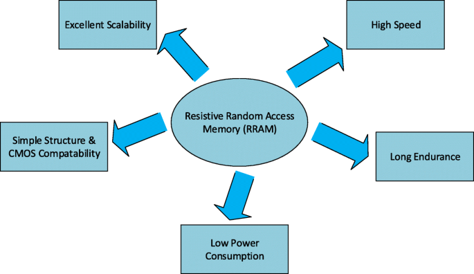
Vorteile von RRAM
In dieser Arbeit werden aktuelle Fortschritte und ein detaillierter Überblick über die RRAM-Technologie vorgestellt. Eine Übersicht über Schaltmaterialien zusammen mit der Klassifizierung von Schaltmodi und Details des Schaltmechanismus wird im Abschnitt „Widerstandsfreier Direktzugriffsspeicher (RRAM)“ diskutiert. Der Abschnitt „Performance Metrics of Resistive Random Access Memory (RRAM)“ beleuchtet verschiedene Leistungsmetriken von RRAM. Multilevel Cell (MLC)-Eigenschaften von RRAM zusammen mit verschiedenen MLC-Operationsschemata und ihren physikalischen Mechanismen werden im Abschnitt „Multilevel Resistive Random Access Memory (RRAM)“ analysiert. Eine detaillierte Diskussion zur Modellierung von RRAM-Geräten wird im Abschnitt „Modellierung von RRAM-Geräten“ präsentiert. Im Abschnitt „Anwendungen von RRAM“ werden verschiedene Anwendungen von RRAM besprochen. Schließlich werden Herausforderungen und Zukunftsaussichten von RRAM im Abschnitt „Herausforderungen und Zukunftsaussichten“ vorgestellt. Die kategorieweise Verteilung der Artikel, die bei der Erstellung dieses Übersichtsmanuskripts herangezogen wurden, ist in Abb. 2 dargestellt.
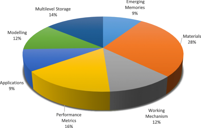
Kategorieweise Verteilung von Artikeln, die für die Vorbereitung der Überprüfung auf RRAM konsultiert wurden
Resistive Random Access Memory (RRAM)
Widerstandsschaltmaterialien
Es wurde beobachtet, dass bei einigen Isolatoren die Widerstandsänderung beim Anlegen des angelegten elektrischen Felds auftritt. Diese Eigenschaft der Widerstandsänderung wurde kürzlich für die Entwicklung zukünftiger nichtflüchtiger Speicher untersucht [17]. Das Widerstandsschaltphänomen wurde bei einer Vielzahl von Oxiden beobachtet, aber binäre Metalloxide wurden als bevorzugtes Schaltmaterial für zukünftige nichtflüchtige Speicheranwendungen hauptsächlich aufgrund ihrer Kompatibilität mit der CMOS-BEOL-Verarbeitung umfassend untersucht. Verschiedene Materialien auf Metalloxidbasis mit nichtflüchtiger Widerstandsschaltung wie Hafniumoxid (HfO x ) [18–23], Titanoxid (TiO x ) [24–31], Tantaloxid (TaO x ) [32–36], Nickeloxid (NiO) [37–40], Zinkoxid (ZnO) [41–46], Zinktitanat (Zn2 TiO4 ) [47], Manganoxid (MnO x ) [48, 49], Magnesiumoxid (MgO) [50], Aluminiumoxid (AlO x ) [51–53] und Zirkoniumdioxid (ZrO2 ) [54–58] haben die meiste Aufmerksamkeit erregt und wurden in den letzten Jahren intensiv untersucht. Diese Metalloxide werden gewöhnlich durch Pulslaserabscheidung (PLD), Atomlagenabscheidung (ALD) und reaktives Sputtern abgeschieden. ALD ist jedoch aufgrund seiner Fähigkeit, die Dicke und Gleichmäßigkeit des Dünnfilms präzise zu steuern, ein weithin bevorzugtes Verfahren [59].
Bei herkömmlichen elektronischen Geräten ist die Wahl des Elektrodenmaterials wichtig, da es als Transportwege für die Träger dient. Bei RRAM beeinflusst die Wahl des Elektrodenmaterials das Schaltverhalten des Bauelements stark. In Kupfer/Poly(3-hexylthiophen):[6,6]-Phenyl-C61-Buttersäuremethylester/Indium-Zinnoxid (Cu/P3HT:PCBM/ITO)-Struktur wurde beispielsweise ein stabiles Widerstandsschaltverhalten beobachtet; es verschwand jedoch, nachdem die Cu-Elektrode durch eine Pt-Elektrode ersetzt wurde [60]. Als Elektroden für RRAM wurden viele verschiedene Materialien verwendet. Die Elektrodenmaterialien können auf der Grundlage ihrer Zusammensetzung in fünf Kategorien eingeteilt werden, einschließlich Elementarsubstanzelektroden, Elektroden auf Siliziumbasis, Legierungselektroden, Oxidelektroden und Elektroden auf Nitritbasis. Die am häufigsten vorkommenden und am häufigsten verwendeten Elektroden sind Elementarstoffelektroden, die Al [51], Ti[49], Cu[30], Graphen [61], Kohlenstoffnanoröhren [62], Ag [41], W [36] umfassen, und Pt [44]. Für siliziumbasierte Elektroden sind p-Si und n-Si [63] die einzigen verwendeten Elektrodentypen. Legierungselektroden stabilisieren normalerweise das resistive Schaltverhalten und umfassen hauptsächlich Cu-Ti [64], Cu-Te [65] und Pt-Al [66]. Die gebräuchlichsten Elektroden auf Nitridbasis sind TiN und TaN [67, 68]. Die Elektroden auf Oxidbasis sind relativ häufig, darunter Al-dotiertes ZnO [69], Ga-dotiertes ZnO [70] und ITO [71].
Die Liste der Metalloxidmaterialien, die in letzter Zeit bei der Herstellung der RRAM-Vorrichtung verwendet wurden, zusammen mit verschiedenen Kombinationen von Materialien, die für die obere Elektrode und die untere Elektrode verwendet wurden, ist in Tabelle 2 gezeigt. Ein detaillierter Vergleich der verschiedenen Parameter wird ebenfalls präsentiert. Aus der großen Vielfalt der verwendeten Materialien kann man vorhersagen, dass das nichtflüchtige Widerstandsschalten bei verschiedenen Oxidtypen häufig beobachtet wird. Die Materialwahl für die Herstellung von RRAM verschafft ihm einen Vorteil, da Metalloxid-Metall-(MOM)-Strukturen leicht hergestellt werden können, indem Oxide verwendet werden, die derzeit in der Halbleitertechnologie verwendet werden. Das Material der unteren Elektrode in RRAM ist normalerweise Platin, das etwas schwer zu ätzen ist. Bei einer Einzelbauelementstruktur kann sich RRAM dieselbe untere Elektrode teilen, während bei der Crossbar-Architektur die separaten unteren Elektroden für jedes Bauelement verwendet werden. Sie können durch physikalisches Aufdampfen und sukzessives Abheben gewonnen werden. Die obere Elektrode und die Widerstandsschaltschicht werden entweder durch Atomlagenabscheidung (ALD) oder physikalische Gasphasenabscheidung (PVD) abgeschieden.
Widerstandsschaltmodi
Ein resistiver Direktzugriffsspeicher (RRAM) besteht aus einer resistiven Schaltspeicherzelle mit einer Metall-Isolator-Metall-Struktur, die allgemein als MIM-Struktur bezeichnet wird. Die Struktur umfasst eine Isolierschicht (I), die zwischen den beiden Metallelektroden (M) angeordnet ist. Die schematische Ansicht und die Querschnittsansicht einer RRAM-Zelle sind in Fig. 3a bzw. b gezeigt.
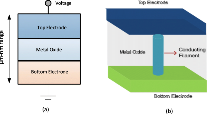
a Schema der Metall-Isolator-Metall-Struktur für RRAM. b Querschnittsansicht des RRAM
Das Anlegen des externen Spannungsimpulses über die RRAM-Zelle ermöglicht einen Übergang des Geräts von einem hochohmigen Zustand (HRS) oder AUS-Zustand, der allgemein als logischer Wert '0' bezeichnet wird, in einen niederohmigen Zustand (LRS) oder EIN-Zustand allgemein als logischer Wert '1' bezeichnet und umgekehrt. Das Phänomen des Widerstandsschaltens (RS) wird als der Grund für diese Änderung der Widerstandswerte in einer RRAM-Zelle angesehen. Ein vorbereiteter RRAM befindet sich zunächst im hochohmigen Zustand (HRS), um das Bauelement von HRS auf LRS umzuschalten, das Anlegen des Hochspannungsimpulses ermöglicht die Bildung von Leiterbahnen in der Schaltschicht und die RRAM-Zelle wird geschaltet in ein LRS [72]. Dieser Prozess, der aufgrund des weichen Zusammenbruchs der Metall-Isolator-Metall-Struktur (MIM) auftritt, wird normalerweise als „Elektroformen“ bezeichnet und die Spannung, bei der dieser Prozess stattfindet, wird als Formierspannung (V f ). Es ist zu beachten, dass die Formierspannung von der Zellfläche [73] und der Oxiddicke [74] abhängt. Um nun die RRAM-Zelle von LRS auf HRS umzuschalten, wird der als RESET-Spannung bezeichnete Spannungsimpuls (V zurücksetzen ) angewendet, die diesen Schaltübergang ermöglicht, und der Prozess wird als „RESET“-Prozess bezeichnet [75–78]. Die HRS des RRAM kann beim Anlegen des Spannungsimpulses auf LRS geändert werden. Die Spannung, bei der der Übergang von HRS zu LRS erfolgt, wird als SET-Spannung bezeichnet (V set ) und der Prozess wird als „SET“-Prozess bezeichnet [79]. Um Daten effizient aus der RRAM-Zelle zu lesen, wird eine kleine Lesespannung, die den aktuellen Zustand der Zelle nicht stört, angelegt, um zu bestimmen, ob sich die Zelle im logischen 0 (HRS) oder im logischen 1 (LRS) Zustand befindet. Da sowohl LRS als auch HRS ihre jeweiligen Werte auch nach Wegnahme der angelegten Spannung beibehalten, ist RRAM ein nichtflüchtiger Speicher. Abhängig von der Polarität der angelegten Spannung kann der RRAM in zwei Arten von Schaltmodi eingeteilt werden:(i) unipolares Schalten und (ii) bipolares Schalten [80]. Beim unipolaren Schalten ist die Umschaltung (Setz- und Rücksetzvorgang) des Gerätes zwischen verschiedenen Widerstandszuständen unabhängig von der Polarität der angelegten Spannung, d. 4a. Beim bipolaren Schalten hingegen ist das Umschalten (Setz- und Rücksetzvorgang) des Gerätes zwischen verschiedenen Widerstandszuständen abhängig von der Polarität der angelegten Spannung, dh ein Übergang von einer HRS zu LRS erfolgt an einer Polarität (entweder positiv oder negativ) und die entgegengesetzte Polarität schaltet die RRAM-Zelle zurück in die HRS, wie in 4b dargestellt. Beim unipolaren Schalten wird die Joulesche Erwärmung als der physikalische Mechanismus interpretiert, der dafür verantwortlich ist, einen leitenden Faden während des Rücksetzvorgangs zu reißen. Beim bipolaren Schalten ist andererseits die Wanderung geladener Spezies die Hauptantriebskraft für die Auflösung des leitfähigen Filaments, obwohl die Joulesche Erwärmung immer noch zur Beschleunigung der Wanderung beiträgt. Um sicherzustellen, dass es während des Formungs-/Setzprozesses des RRAM keinen dauerhaften Durchbruch der dielektrischen Schaltschicht gibt, wird ein Compliance-Strom (I cc ) wird für das RRAM-Gerät erzwungen. Der Compliance-Strom (I cc ) wird in der Regel durch eine Zellenauswahlvorrichtung (Transistor, Diode, Widerstand) oder durch einen Halbleiterparameteranalysator während des Off-Chip-Tests sichergestellt.
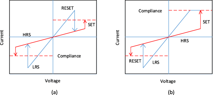
I-V-Kurven für RRAM. a Unipolares Schalten und b bipolares Schalten [4]
Resistiver Schaltmechanismus
Das Schalten der RRAM-Zelle basiert auf dem Wachstum eines leitfähigen Filaments (CF) innerhalb eines Dielektrikums. Der CF ist ein Kanal mit einem sehr geringen Durchmesser in der Größenordnung von Nanometern, der die obere und die untere Elektrode der Speicherzelle verbindet. Ein niederohmiger Zustand (LRS) mit hoher Leitfähigkeit wird erreicht, wenn die Wendel angeschlossen wird, und der hohe Widerstand (HRS) ergibt sich, wenn die Wendel mit einem Abstand zwischen den Elektroden getrennt wird [91]. Basierend auf der Zusammensetzung des leitfähigen Fadens kann RRAM in die folgenden zwei Typen eingeteilt werden:(i) Metallionen-basierter RRAM, auch als leitfähiger Brückenspeicher mit wahlfreiem Zugriff (CBRAM) bezeichnet und (ii) Sauerstoffleerstellen fadenbasierter RRAM bezeichnet als 'OxRRAM'. An dieser Stelle sei darauf hingewiesen, dass CBRAM manchmal als elektrochemischer Metallisierungsspeicher (ECM) bezeichnet wird, während „OxRRAM“ manchmal auch als Valenzänderungsspeicher (VCM) bekannt ist.
In Metallionen-basierten RRAMs, auch als „CBRAM“ bezeichnet, basiert der physikalische Mechanismus, der für das resistive Schalten verantwortlich ist, auf der Migration von Metallionen und anschließenden Reduktions-/Oxidations-(Redox)-Reaktionen [92, 93]. Die CBRAM-Struktur besteht aus einer oxidierbaren oberen Elektrode (Anode) wie Ag, Cu und Ni, einer relativ inerten unteren Elektrode (Kathode), z. W, Pt und eine sandwichartige Metalloxidschicht zwischen den beiden Elektroden. Die Filamentbildung in solchen Speicherzellen erfolgt durch die Auflösung der aktiven Metallelektroden (meist Ag oder Cu), den Transport von Kationen (Cu + oder Ag + ) und deren anschließende Abscheidung oder Reduktion an der inerten unteren Elektrode [94]. Somit wird das Widerstandsschaltverhalten dieser Art von RRAM von der Bildung und Auflösung der Metallfilamente dominiert.
Um den Schaltmechanismus von Metallionen-basierten CBRAMs besser zu verstehen, betrachten wir ein Beispiel von Ag/a-ZnO/Pt-RRAM-Zellen [41]. Eine allgemeine schematische Darstellung, die den Schaltprozess einer Direktzugriffsspeicherzelle mit leitender Brücke darstellt, ist in 5 gezeigt. Der ursprüngliche Zustand der CBRAM-Speicherzelle ist in 5a dargestellt. Die obere Ag-Elektrode (TE) ist eine aktive Komponente bei der Filamentbildung, während die untere Pt-Elektrode inert ist. Beim Anlegen der positiven Vorspannung an die obere Ag-Elektrode wird die Oxidation (Ag → Ag + + e − ) tritt an der oberen Elektrode auf, wodurch Ag + Kationen werden erzeugt und von der Ag-Elektrode in die dielektrische Schicht (a-ZnO) abgeschieden. Die negative Vorspannung an der unteren Pt-Elektrode (BE) zieht das Ag + . an Kationen und damit die Reduktionsreaktion (Ag + + e − → Ag) tritt an der unteren Elektrode auf. Somit ist das Ag + Kationen werden zu Ag-Atomen reduziert und akkumulieren, bis die leitende Brücke gebildet ist (Abb. 5b–d) und das RRAM-Bauelement LRS aufweisen soll. Dieser Vorgang wird als „SET“ bezeichnet. Wenn die Polarität der angelegten Spannung umgekehrt wird, löst sich der hochleitende Glühfaden fast vollständig auf und das Gerät befindet sich im hochohmigen Zustand (HRS). Dieser Vorgang wird als „RESET“ bezeichnet und ist in Abb. 5e dargestellt.
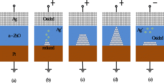
Schema des Schaltmechanismus des RRAM mit leitfähiger Brücke. a Unberührter Zustand des RRAM-Geräts. b , c Oxidation von Ag und Migration von Ag + Kationen zur Kathode und deren Reduktion. d Die Ansammlung von Ag-Atomen und der Pt-Elektrode führt zum Wachstum eines hochleitfähigen Filaments. e Die Filamentauflösung erfolgt beim Anlegen einer Spannung mit entgegengesetzter Polarität [41]
Bei einem auf Sauerstoffleerstellen basierenden RRAM (OxRRAM) ist der physikalische Mechanismus, der für das Widerstandsschalten verantwortlich ist, im Allgemeinen mit der Erzeugung von Sauerstoffleerstellen (V \(_{o}^{2+}\)) und anschließende Verlagerung von Sauerstoffionen (O 2− ), wodurch die Bildung eines leitfähigen Filaments zwischen den oberen und unteren Elektroden der RRAM-Zelle ermöglicht wird [59]. Anfänglich ist für die RRAM-Zelle, wie sie hergestellt wurde, ein Formgebungsprozess, d. h. ein weicher Durchbruch des Dielektrikums, wesentlich. Sobald der weiche dielektrische Durchschlag auftritt, werden die Sauerstoffatome beim Anlegen eines hohen elektrischen Feldes in Richtung der Anodengrenzfläche aus dem Gitter geschlagen und werden zu Sauerstoffionen (O 2− ), während die Sauerstoffleerstellen (V \(_{o}^{2+}\)) verbleiben in der Oxidschicht. Die Sauerstoffionen (O 2− ) reagieren mit Anodenmaterialien oder werden als neutraler Nichtgitter-Sauerstoff entladen, wenn die Edelmetalle als Materialien für die Anode verwendet werden, um eine Grenzflächenoxidschicht zu bilden. Somit verhält sich die Elektrode/Oxid-Grenzfläche wie ein „Sauerstoffreservoir“ [85]. Als nächstes wird die Ansammlung der Sauerstoffleerstellen (V \(_{o}^{2+}\)) im Bulk-Oxid schaltet die RRAM-Zelle in den niederohmigen Zustand (LRS), wenn der leitfähige Faden (CF) gebildet wird und der merkliche Strom in der Vorrichtung fließt. Um das Gerät wieder in den hochohmigen Zustand (HRS) zu schalten, erfolgt der Reset-Vorgang, bei dem die Sauerstoffionen (O 2− ) wandern von der Anodengrenzfläche zum Bulk-Oxid zurück und verbinden sich entweder mit den Sauerstoffleerstellen (V \(_{o}^{2+}\)) oder die metallischen CF-Ausscheidungen zu oxidieren und damit den Faden teilweise zu zerreißen, wodurch die RRAM-Zelle wieder in HRS umgeschaltet wird. Bei RRAM-Zellen mit unipolarem Schaltmechanismus ist die Diffusion von Sauerstoffionen (O 2− ) wird thermisch durch einen Jouleschen Heizstrom aktiviert und als solche diffundieren die Sauerstoffionen aufgrund des Konzentrationsgradienten aus der Grenzfläche oder dem Bereich um den CF herum. Außerdem muss beachtet werden, dass in unipolar schaltenden RRAMs ein relativ höherer Rücksetzstrom erforderlich ist, um die lokale Temperatur um CF herum zu erhöhen. Im bipolar schaltenden RRAM hingegen sind die Sauerstoffionen (O 2− ) muss durch das umgekehrte elektrische Feld unterstützt werden, da die Grenzschicht eine erhebliche Diffusionsbarriere darstellen kann und eine reine thermische Diffusion nicht ausreicht. Es muss beachtet werden, dass in beiden Fällen der teilweise Bruch von CF stattfindet, wodurch die RRAM-Zelle in den hochohmigen Zustand (HRS) geschaltet wird. Dies ist hauptsächlich auf die Bildung von Sauerstoffleerstellen (V \(_{o}^{2+}\)) und ein schlechter Bereich, was zu einer Tunnellücke für Elektronen führt. Um das Gerät wieder auf den LRS (SET-Prozess) umzuschalten, verbindet der CF die Elektroden aufgrund des weichen Durchbruchs im Gap-Bereich wieder. Ein ähnlicher Set/Reset-Vorgang kann sich über viele Zyklen wiederholen.
Basierend auf der obigen Diskussion beruht CBRAM, auch als elektrochemischer Metallisierungsspeicher (ECM) bekannt, auf einer elektrochemisch aktiven Metallelektrode wie Ag, Cu oder Ni, um CF auf Metallkationenbasis zu bilden [95]. Der CF in filamentbasierten Sauerstoffleerstellen-RRAM „OxRRAM“, auch bekannt als Valenzänderungsspeicher (VCM), besteht aus Sauerstoffleerstellendefekten anstelle von Metallatomen aufgrund der Anionenwanderung innerhalb des Speichermaterials selbst [96]. Obwohl der Schaltmechanismus sowohl von „OxRRAM“ als auch von „CBRAM“ ausführlich diskutiert wird, gibt es noch einige Diskussionen über die Schaltmechanismen beider RRAM-Typen [97]. Zum Beispiel, wo der CF im Setzprozess zu wachsen beginnt und wo er im Resetprozess bricht und wie sich diese Sauerstoffleerstellen/Metallatome zu CF zusammenfinden. Die Strom-Spannungs-Eigenschaften (I-V) von 20 aufeinanderfolgenden Schaltzyklen von Ta/TaO x /Pt [98]-basierte RRAM-Strukturen wurden untersucht, und es wurde die deutliche Variation von LRS und HRS für aufeinanderfolgende Schaltzyklen beobachtet. Als Ergebnis verringert sich das Gesamtspeicherfenster, was die Gesamtleistung des RRAM verschlechtert. Diese Widerstandsvariabilität von Zyklus zu Zyklus wird in erster Linie der zufälligen Bildung von CF sowie seinem Aufbrechen während des Setz- bzw. Rücksetzvorgangs zugeschrieben.
Ein Vergleich von OxRRAM mit CBRAM basierend auf verschiedenen Betriebsparametern ist in Tabelle 3 dargestellt [81, 84, 86–88, 99, 100]. Dieser Vergleich zeigt den markanten Unterschied in Bezug auf die Ausdauereigenschaften dieser RRAM-Speichertypen. Diese Unähnlichkeit ist darauf zurückzuführen, dass die leitenden Filamente von CBRAM hauptsächlich aus Metallatomen bestehen, die im Vergleich zu Sauerstoffleerstellen relativ leichter zu driften und zu diffundieren sind, wodurch die Retentionszeit und die Lebensdauereigenschaften von CBRAM im Vergleich zu OxRRAM verschlechtert werden. Obwohl der Schaltmechanismus der beiden RRAM-Typen unterschiedlich ist, gibt es viele gemeinsame Merkmale zwischen den beiden. Der einzige signifikante Unterschied besteht darin, dass die Ausdauer bei OxRRAM deutlich höher ist als bei CBRAM.
Leistungskennzahlen des resistiven Direktzugriffsspeichers (RRAM)
Ausdauer
Resistiver Direktzugriffsspeicher beinhaltet häufige Übergänge zwischen einem hochohmigen Zustand (HRS) und einem niederohmigen Zustand (LRS). Jedes Schaltereignis zwischen den Widerstandszuständen kann einen dauerhaften Schaden einbringen und eine Verschlechterung der RRAM-Leistung verursachen. Ausdauer ist somit definiert als die Häufigkeit, mit der ein RRAM-Baustein zwischen HRS und LRS umgeschaltet werden kann, während ein zuverlässig unterscheidbares Verhältnis zwischen ihnen sichergestellt wird [101]. So ermittelt ein Dauertest die maximale Anzahl von Set-/Reset-Zyklen, die effektiv geschaltet werden können, bevor HRS und LRS nicht mehr unterscheidbar sind. Die Lebensdauereigenschaften von RRAM werden durch Ausführen einer Folge von I-V-Sweeps in einer Widerstandsschaltzelle und der anschließenden Extraktion von R . erhalten HRS und R LRS beim Anlegen einer Lesespannung (typischerweise 0,1 V) [41]. Dieses Verfahren ist zuverlässig, da man in jedem Zyklus das korrekte Schalten des Geräts erreichen kann; Diese Methode ist jedoch sehr langsam, da die erforderliche Zeit zum Erhalten eines I-V-Sweeps sehr viel länger sein kann, insbesondere wenn es sich um niedrigere Ströme handelt.
Die Ausdauerzyklen in einem H f O x Die RRAM-Zelle zeigt eine starke Abhängigkeit von der Zellgröße, wie in Fig. 6a dargestellt, wobei eine bessere Lebensdauer bei RRAM-Vorrichtungen mit größerer Zellgröße berichtet wird. Darüber hinaus führt eine vertikale Reduzierung der Schichtdicke zu einer Verschlechterung der Dauerleistung für die SET-Spannung bei 2,5 V, wie in Abb. 6b [102] gezeigt. Diese Verschlechterung der Dauerleistung mit Verkleinerung der Schaltschicht ist ein Ergebnis der reduzierten Anzahl von Ionen im aktiven Bereich. H f O x -basierter RRAM weist eine hervorragende Ausdauerleistung von 10 6 . auf Zyklen auf einem 1-kb-Array mit 30-nm-Zellengröße unter 0,18 μ m-Technologie und das gleiche ist in Abb. 6c [103] dargestellt. Durch Hinzufügen einer zusätzlichen Schicht A l O x oberhalb der unteren Elektrode (BE) kann die Array-Stabilität weiter verbessert werden, da die Lesestörfestigkeit für HRS erhöht wird. Für T a O x -basierten RRAM wurde eine Verschlechterung der Ausdauerleistung mit zunehmender Pulsbreite und Amplitude der RESET-Spannung in Ta/Ta2 . beobachtet O5 /TiN-RRAM-Struktur [105]. Ein Vergleich der unteren Elektrode von TiN und Ru in der Ta/Ta2 O5 /TiN RRAM zeigt, dass die Hauptursache für die Verschlechterung der Lebensdauer auf die Reaktion von Sauerstoffionen mit der TiN-Elektrode zurückzuführen ist. Darüber hinaus eine verbesserte Ausdauer von 10 9 Schaltzyklen wurden ohne Überprüfung in einer ähnlichen RRAM-Struktur durch Reduzieren von Ta2 . erhalten O5 Schicht bis auf 3 nm herunter [106] und Verwendung von Dreieckspulsen mit <5 ns Breite. Für die Leistung eines großen Arrays ein Vergleich von 2 Mb Ta2 O5 Speicher vor und nach 10 5 Zyklen des Dauertests ist in Abb. 6d [104] dargestellt. Die Zellstromverteilungen zeigen eine kleine Variation für Anfangs- und Endzyklen. Außerdem fällt der Zellenstrom für LRS unter 50 μ A, was auf einen geringen Stromverbrauch des Arrays hinweist. The resistive switching devices with endurance higher than 10 12 cycles have been reported in different types of RRAM cells involving tantalum oxide (TaO x )-based switching mediums [32, 36, 59]. Thus, tantalum oxide-based RRAM devices seem to be exhibiting the highest endurance.
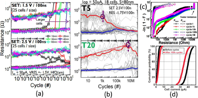
a Endurance cycles of H f O x -based RRAM at different SET voltage and cell size b with different thickness (T5=2 nm, T20=10 nm) at 2.5 V set voltage. c Resistance distribution of 1-kb array obtained from Weibull plots under different endurance cycles. d 100 k cycles endurance of 2-Mb-Ta2 O5 -based array; Reprinted from refs [102–104]
Retention
The data retention of a RRAM device involves investigating stability over a period of time for both LRS and HRS after undergoing set and reset transitions. In other words, the time period for which a memory cell will remain in a particular state after the set/reset operation determines the capability of a memory cell to retain its content [11]. The application of the constant voltage stress (CVS) over time using a low read voltage (0.1 V) and the measurement of the current versus time (I-t) curve for both LRS as well as the HRS enables the measurement of state retention. Due to the dispersing nature of atomic rearrangements induced in RRAM because of set voltage, the long retention time in LRS is difficult to obtain whereas, in HRS, retention is not a concern as it is usually the natural state of the device and RRAM will continue to remain in this state if no bias (or low bias) is applied. The retention in the LRS depends on the compliance limit during the SET transition, e.g. in RRAMs based on conductive filament switching mechanism, the larger compliance current produces a stronger conducting filament which is more stable over time [28, 41], as compared to a smaller compliance current. A projected endurance of 10 years at 85 ∘ C has been demonstrated in Ti/HfO2 /TiN [18]. A commonly used method to obtain device endurance is by applying read pulse at high temperature after certain time intervals (e.g. every 1 s) and extrapolate the resistance to a 10-year period. Although this method is easy to implement, it has certain limitations primarily due to the read voltage stress applied to the cell. An alternative method is to change the temperature and record the time until the device fails. Activation energy is extracted by plotting the Arrhenius plot and extrapolate down to the operating temperature. However, the limitation of this method is that waiting is necessary until the failure occurs in the RRAM cell, and thus, this method is more time-consuming and expensive.
The device characteristics of H f O x -based RRAM [81, 103] developed at the Industrial Technology Research Institute, Taiwan, are demonstrated to further understand the working of RRAM device. The transmission electron microscopy (TEM) image of the TiN/Ti/ H f O x /TiN RRAM device with 30-nm cell size is shown in Fig. 7a. The device exhibits bipolar switching characteristics and the I-V curve obtained at 200 μ A set compliance current is shown in Fig. 7b. The device presents endurance of 10 6 switching cycles with the resistance on/off ratio greater than 100 at set/reset programming conditions of + 1.5 V/– 1.4 V pulse with 500 μ s pulse width and the same is depicted in Fig. 7c.
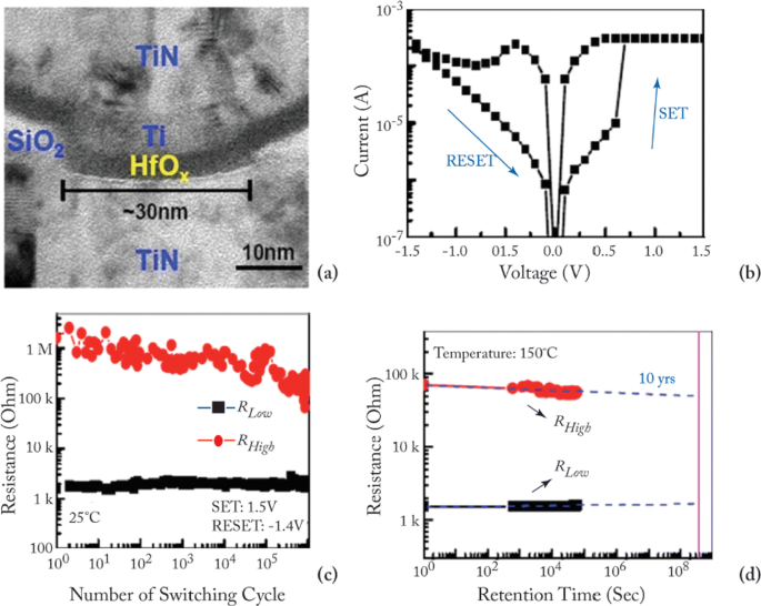
a Transmission electron microscopy (TEM) image of TiN/Ti/HfO x /TiN RRAM device. b Typical current-voltage (I-V) characteristics of the device with 30-nm cell size. c 10 6 endurance switching cycles obtained from 500 μ s pulse. d A retention lifetime of 10 years is expected by testing at 150 ∘ C; reprinted from refs. [81, 103]
Uniformity
In RRAM cell, poor uniformity of various device characteristics is one of the significant factors limiting the manufacturing on a wider scale. The switching voltages, as well as both the HRS and the LRS resistances, are among the parameters exhibiting a high degree of variation. The variations of the resistance switching include temporal fluctuations (cycle-to-cycle) and spatial fluctuations (device-to-device). The stochastic nature of the formation and rupture of conductive filament is believed to be the main reason for these variations. Cycle-to-cycle and device-to-device variability is a major hindrance for information storage in RRAM devices [59]. The observation of cycle-to-cycle variability is influenced by the change in the number of oxygen vacancy defects that arise in the CF due to its stochastic nature of formation and rupture during the switching event [107]. Due to this random nature of the CF, the prediction and the precise control of the shape of the CF becomes extremely challenging. This variability becomes worse as the compliance limit (i.e. compliance current ‘I cc ’) is reduced. On the other hand, for the higher value of ‘I cc ’, the ratio of standard deviation (σ ) and average resistance (μ ) is low, resulting in a smaller LRS resistance spread. This is attributed to the higher defects in the CF, thus forming a well-defined path for current conduction.
RRAM also exhibits device-to-device (cell-to-cell) non-uniformity which also degrades the memory performance by reducing the memory margin between two states. The origin of this variability is attributed to the non-uniformities in the fabrication process such as the thickness of the switching film, etching damages and surface roughness of the electrodes. A lot of research has been conducted to improve the uniformity of RRAM and several methods have been explored for the same. One of the methods utilizes the concept of inserting nano-crystal seeds which confine the paths of the conductive filament by enhancing the effect of local electric field [82, 90, 108]. In Ti/TiO 2−x /Au-based RRAM [28], the induction of platinum (Pt) nano-crystals within the thin TiO 2−x results in an enhanced uniformity of the RRAM cell. The Pt nano-crystals limit the switching effect into regions with high oxygen vacancy generation probability which results in improved uniformity. In another approach, engineering the electrode/oxide interface by embedding appropriate buffer layers is very useful in achieving uniform RRAM operation. In HfO x -based RRAM [109], a thin Al buffer layer is inserted between the TiN electrode and HfO x oxide layer. This results in significant improvement of set voltage distribution as well as the resistance distribution, thus enhancing the uniformity of the device. The improvement in the SET voltage and the resistance distribution of the RRAM device after inserting a thin Al buffer layer between TiN electrode and HfO x bulk oxide and the same is depicted in Fig. 8 [59]. Al atoms are assumed to diffuse into HfO2 thin films, and they tend to localize oxygen vacancies due to the reduced oxygen vacancy formation energy, thus stabilizing the generation of conductive filaments, which helps to improve the resistance switching uniformity.
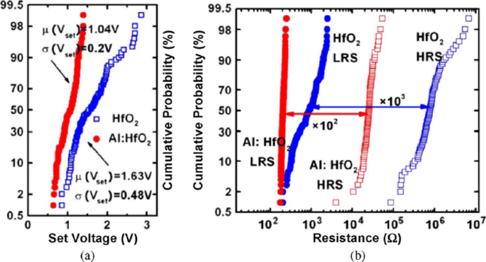
Uniformity improvement of Al buffered HfO x RRAM compared to HfO x -based RRAM array. a Statistical distribution of SET voltage (V set ) obtained from 100 DC sweep cycles. b HRS and LRS statistical distribution for 100 pulse sweep cycles; reprinted from ref. [59]
In addition to the materials engineering approach, a novel programming method has also been suggested to reduce fluctuations. A multistep forming technique was implemented in W/HfO2 /Zr/TiN [22]-based RRAM to minimize the overshoot current due to the parasitic effects. A multi-step forming technique results in the gradual formation of the filament; thus, a low set/reset current is achieved improving the switching characteristics of the device. Various other methods such as constant voltage forming and hot forming (usually referred to as forming at a higher temperature) have also been investigated to effectively reduce the resistance variations [110]. Another method of achieving high uniformity is by applying a pulse train rather than a single pulse to a RRAM cell [23]. This approach not only results in improved uniformity but also enhances the multilevel capability of a RRAM cell.
Effect of Operating Temperature and Random Telegraph Noise
To achieve a reliable performance of the RRAM device, the effect of operating temperature and random telegraph noise (RTN) is investigated. It is observed that the resistance of both the LRS and HRS states undergoes variations because of the change of operating temperature. The temperature study of TiN/HfO2 /Ti/TiN [111] was carried out. A positive sweep voltage of <3 V magnitude and compliance current of 1 μ A was applied for the electroforming. Once forming takes place, a reset voltage (V zurücksetzen ) <–1 V switches the device back to the HRS (OFF state). To switch the device back to the LRS (ON state), set voltage (V set ) <1 V is applied.
The reset operation in RRAM device tends to show voltage-controlled negative differential resistance (NDR). The reset operation occurs abruptly at low temperatures, while for temperatures above room temperature, the reset process takes place more gradually. The resistance of the RRAM device in the pristine state, as well as the ON state and OFF state as a function of temperature is depicted in Fig. 9a. The semiconducting behavior is observed for the pristine state as well as the OFF state, i.e. resistance decreases with increase of temperature. For the ON state, a metallic characteristic is observed, i.e. resistance increases with increase of temperature. Due to the variation of resistance with change in temperature, R OFF /R ON also decreases from a value of 20 to approximately 5 over the temperature range of 213–413K. In Ti/HfO x /Pt devices, decrease in R OFF /R ON was observed with temperature-dependent cycling. This decrease in resistance ratio was attributed to the built-up of oxygen-vacancy-related traps inside the HfO2 metal oxide layer [112, 113]. Additionally, temperature-dependent measurements without set/reset operation were carried out to evaluate the impact of I-V cycling on the R OFF /R ON Verhältnis. The sweep voltage across the RRAM device was stopped before reaching V set und V zurücksetzen Werte. For OFF state resistance (green rectangles), a weaker temperature dependence was observed in contrast to the ON state resistance (green circles) which exhibited similar characteristics, compared to the cycling case. From these observations, we infer that I-V cycling induces stronger temperature dependence, which decreases the R AUS /R EIN Verhältnis. The effect of temperature variation on the switching voltages V set und V zurücksetzen is depicted in Fig. 9b. The slight variation in V set with changing temperature indicates that there is no significant temperature difference. For the case of V zurücksetzen , the general trend is that a decrease in voltage value of about 0.2 V with temperature increase in the range of 233–333K is observed. Also, a slow increase of V zurücksetzen is observed for 353–413K temperature range.
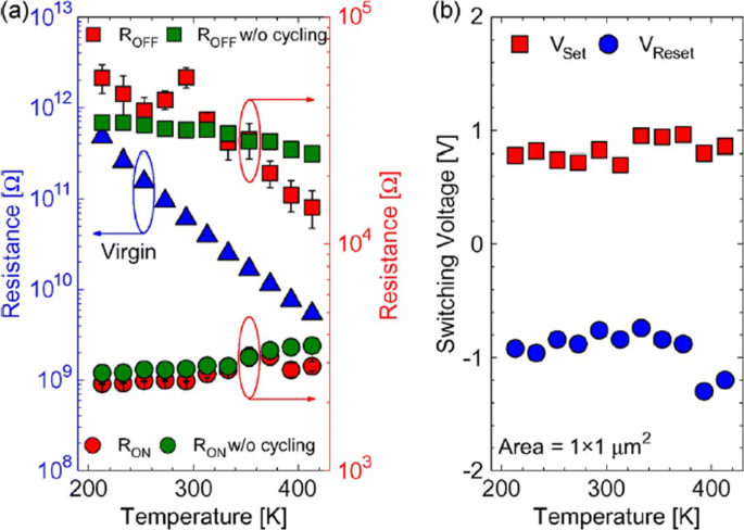
The effect of varying temperature on a virgin resistance (left axis) and the OFF-state as well as the ON-state resistances (right axis) at 213–413K temperature range and b switching voltages V set und V zurücksetzen; reprinted from ref. [111]
Random telegraph noise (RTN) is another factor that affects the performance of RRAM. RTN has for long been used as an indicator of device performance and reliability. RTN decreases the memory margin between the HRS and LRS because of the extensive fluctuations in the read current during the read operation. Due to the effect of RTN, the read margin, scaling potential and the multilevel cell capability of a RRAM cell are greatly affected [114]; thus, it needs to be investigated to achieve reliable performance. To investigate the effect of bottom electrode on RTN, an analysis of Ta2 O5 /TiO2 RRAM [115] was carried out. The examples of complex RTN signals in LRS and HRS are depicted in Fig. 10. RTN causes read instability in the RRAM device, thus reducing the read margin, multibit storage implementation and hindering device scaling. The RTN is attributed to the trapping and de-trapping of electrons in the proximity of the CF in LRS whereas it occurs in the tunneling gap in the HRS state. Although the physics of RTN is still not clear and is being highly debated, the electron trapping and de-trapping which temporarily inhibits the charge transport is widely accepted as the mechanism responsible for fluctuation due to RTN. It is observed that with the decrease in operation current, the amplitude of RTN increases, thus highly affecting the HRS level. Therefore, it is necessary to ensure the additional resistance margin to achieve reliable performance. RTN in RRAM has been researched extensively, although the physical mechanism of RTN is still not explicitly defined. RTN can be utilized as a tool to map the movements of active vacancies in RRAM due to its time-dependent variation. This might be quite useful to understand the failure mechanisms of other reliability issues.
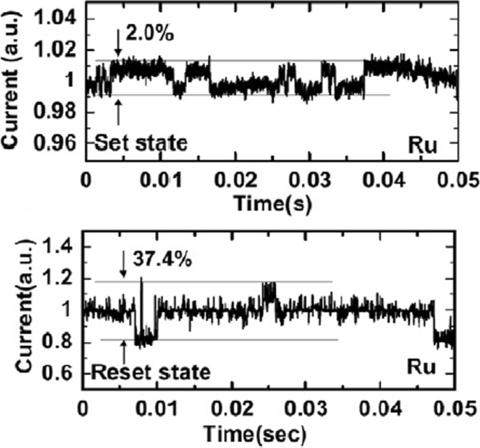
Complex RTN signals in LRS and HRS of Ta2 O5 /TiO2 -based RRAM depicting normalized noise amplitude and average current; reprinted from ref. [114]
Multilevel Resistive Random Access Memory (RRAM)
Multilevel Per Cell (mlc) Storage
Owing to their small physical size and low power consumption, RRAM devices are potential for future memory and logic applications. Increased storage density is among the most critical aspects of memory technology to enable the design of multibit capacity [89] memory cells. The multiple resistive states can be achieved in RRAM cells which provide benefits of low-cost and high-density non-volatile data storage solutions. Currently, a lot of research is being conducted in the area of RRAM to scale down the dimensions and increase the structural density of memory arrays. Previously, the storage density of RRAM has been increased by the reduction of device size; however, the complexity involved in the experimental procedures limits its successful implementation. Another suggested method is employing three-dimensional (3D) crossbar architectures. Two types of architectures of ‘vertical’ and ‘crossbar RRAM’ have been proposed [116, 117]; however, both these architecture types require advanced fabrication procedures which is not desirable. A much simpler alternative to increase storage density in RRAM devices is by making use of multilevel cell (MLC) storage technology which enables storing more than one bit per cell without reducing the physical device dimensions. This MLC is one of the most promising properties of RRAM which can significantly increase the memory storage density [83, 118–125]. Thus, instead of a single high and low resistance state (HRS and LRS), we can achieve multiple HRS and LRS, without changing the device dimensions. However, to achieve reliable MLC operation, the precise control over the resistance of the different resistance levels of RRAM should be ensured; otherwise, the device will suffer from resistance variability and reliability issues mainly due to the random nature of the conductive filament formation during the switching process [126].
Methods to Obtain Multilevel Per Cell (mlc) Modes in RRAM
The MLC behavior in RRAM makes it very useful for high-density applications. To obtain MLC behavior in RRAM, the following three methods are employed:(i) changing compliance current, (ii) controlling reset voltage and (iii) varying pulse width of program/erase operation.
MLC by Changing Compliance Current
The RRAM device is usually operated with 1-RRAM (1R) cell configuration [41] or in 1-Transistor 1-RRAM (1T-1R) cell configuration [18]. The MLC characteristics in 1R configuration can be obtained by changing the current compliance (I cc ) during ‘set’ operation whereas the MLC characteristics in 1-Transistor 1-RRAM (1T-1R) cell structure are controlled by varying the voltage at the gate of the transistor, which enables the control of compliance current (I cc ) during the set operation of a RRAM cell. The typical MLC I-V curves of Ti/Ta2 O5 /Pt [127] based RRAM cell are shown in Fig. 11. As the compliance current (I cc ) is increased from 150 μ A to 1 mA, six different LRS are obtained at I cc =150 μ A, I cc =200 μ A, I cc =300 μ A, I cc =500 μ A and I cc =700 μ A, I cc =1 mA due to the increase in the respective current of LRS (I LRS ) while the HRS is maintained constant and the HRS current (I HRS ) remains same for all the LRS levels. For Ti/Ta2 O5 /Pt RRAM, with the increase in I cc , the maximum reset current (I reset ) also increases while the set voltage is almost maintained constant. Also, it was observed that the resistance of the LRS (R LRS ) decreases while the (I reset ) increases owing to the stronger filament formation with the increase in I cc .
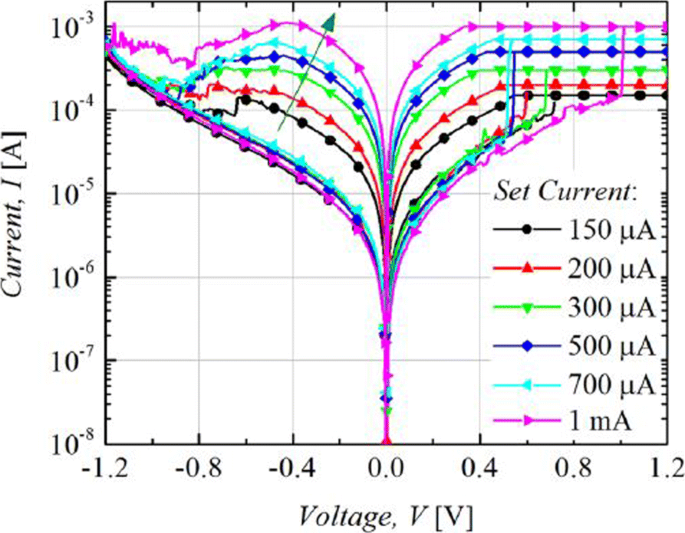
Multilevel characteristics of Ti/Ta2 O5 /Pt RRAM obtained by controlling the compliance current. ‘Reproduced from [127], with the permission of AIP Publishing’
The formation of the CF and its corresponding widening with an increase in I cc is the attributed mechanism of multilevel per cell (MLC) in compliance current (I cc ) mode as depicted schematically in Fig. 12. With an increase in the size of CF because of an increase of I cc , the resistance of the CF decreases and hence results in multiple LRS levels for different values of I cc . It is also observed that I reset increases with increasing I cc as higher power is required to rupture the CF having larger diameter.
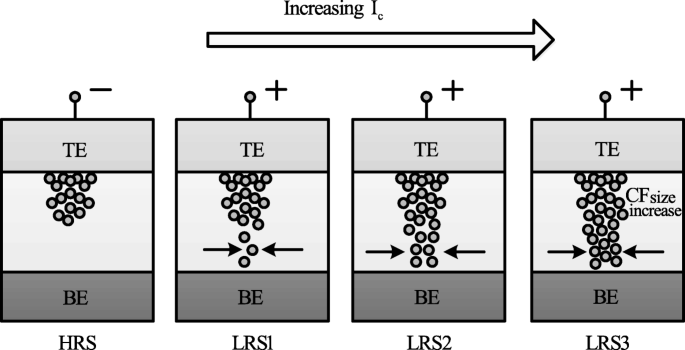
Schematic illustration of multiple resistance states in RRAM cell obtained by varying compliance current ‘I cc ’ [98]
MLC by Controlling Reset Voltage
The MLC characteristics in a RRAM cell can also be obtained by controlling the reset voltage (V zurücksetzen ) while (I cc ) is maintained constant. In this case, the typical MLC I-V curves of TiN/HfO x /AlO x /Pt-based RRAM cell [128] by applying different (V zurücksetzen ) of − 2.1 V, − 2.7 V and − 3.3 V are shown in Fig. 13.
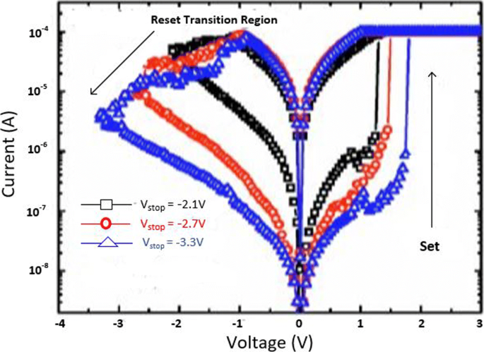
Multilevel characteristics of TiN/HfO x /AlO x /Pt RRAM obtained by controlling the reset voltage. ‘Reproduced from [128], with the permission of AIP Publishing’
It is observed that with an increase in (V zurücksetzen ), the HRS current (I HRS ) decreases; thus, multiple HRS levels with the same LRS resistance are obtained. In addition, the set voltage (V set ) also increases as V zurücksetzen is increased while as the I zurücksetzen remains almost constant.
The decrease in I HRS with the increase in reset voltage is primarily due to the increase in the gap between the metal electrode and tip of the CF as depicted in Fig. 14. The more the magnitude of the V zurücksetzen , the larger the gap and thus the higher the value of resistance. Therefore, an increase in the gap between the CF tip and bottom electrode (BE) with increasing reset voltage results in multiple resistance levels of HRS. It is observed that the devices in which the I zurücksetzen shows a gradual change in current instead of the abrupt change during the ‘reset’ operation, the change in HRS resistance in such devices can be due to decrease in the size of the conductive filament (CF) as V zurücksetzen is increased. This approach is more viable practically for cross-point architectures as it requires relatively lower complex circuitry.
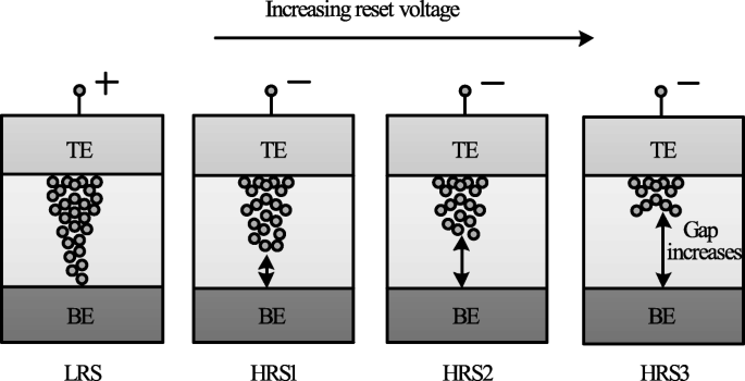
Schematic illustration of multiple resistance states in RRAM cell obtained by varying reset voltage ‘V reset ’ [98]
MLC by Varying Program/erase Pulse Width
MLC characteristics can also be obtained by varying the program/erase pulse width while the amplitude of the pulse is maintained constant [23]. In HfO x -based RRAM [128], three HRS levels were demonstrated by varying the width of the reset pulse from 50 ns to 5 μ S. This method of obtaining MLC characteristics in RRAM is relatively easier; however, this scheme is energy inefficient. This drawback limits the application of this method to obtain reliable characteristics in the RRAM cell. The higher energy consumption of the RRAM device was confirmed on the comparison of the transient responses between the reset pulse amplitude and pulse width control. This is particularly due to the higher unwanted energy dissipation as the thermal energy in the resistive switching material.
A summary of RRAM devices exhibiting multiple resistance states is shown in Table 4. As is evident from the table, various RRAM devices with multiple resistance states have been reported. Till date, however, only 8 resistance states have been demonstrated in a single RRAM cell either by varying I cc or V zurücksetzen . Therefore, there is a huge scope for increasing the number of resistance states in the RRAM cell, thus enhancing its storage density.
Modeling of RRAM Devices
Modeling plays a very critical role in development of devices utilizing semiconductor technologies. To fully understand device operation and to optimize the performance, an accurate model is of great importance. A number of RRAM models with varying features and accuracy have been proposed [129]. This section discusses the characteristics and attributes of the various commonly used RRAM models popular.
Stanford/ASU Model
One of the most popular physics-based RRAM models is the Stanford/ASU RRAM model [130–132], proposed by Guan et al. and Chen et al. This model was applied to validate the I-V switching characteristics of HfO2 RRAM [128] and includes the effect of Joule heating and temperature change on the switching of RRAM devices.
This model is dependent on the CF growth inside a dielectric switching layer. The filament gap, i.e. the gap between the tip of the CF and top electrode, is the internal state variable for this model. The growth of CF inside a dielectric is attributed to the oxygen ion movement and regeneration and recombination of oxygen vacancies [133]. Thus, the rate of change of filament gap (g) is given as [130]:
$$ {\frac{dg}{dt}} =V_{\tiny{0}}.\exp\bigg({{\frac{-E_{a},m}{k_{b}.T}} }\bigg). {\text{Sinh}} \bigg({\frac{qa_{h}\gamma V}{L.k_{b}.T}}\bigg) $$ (1)wo E a is the activation energy, V is the magnitude of the voltage applied across the device, L is the switching material thickness, a h is the hopping distance, γ is the local field enhancement factor, V 0 is the velocity containing attempt to escape frequency, K b is the Boltzmann constant, q is the elementary unit charge and T is the temperature of the conductive filament.
The spatial variation in the gap size is accounted for in this model, in addition to the variations which arise due to the stochastic property of the ion process. A noise signal is added to the gap distance to account for these variations as [130]:
$$ g_{|t+\Delta t} =F \Big[ g_{|t}, {\frac{dg}{dt}} \Big] + \delta_{g}\times\tilde{X}(n)\Delta t, n ={\frac{t}{T_{GN}}} $$ (2)where Δ t is the simulation time step, the function F represents time evolution of gap size fromt to Δ T. \(\tilde {X}\)(n) is a zero mean Gaussian noise sequence. T GN is the time interval after which \(\tilde {X}\)(n ) changes to next random value.
The variation in the gap size δ g depends on kinetic energy of ions and filament temperature as [130]:
$$ \delta_{g} (T) ={\frac{\delta^{\tiny{0}}_{g}}{\bigg\{ 1+\exp \Big({\frac{T_{\text{crit}}- T}{T_{\text{smith}}}} \Big) \bigg\}}} $$ (3)where \(\delta ^{0}_{g}\) and T smith are fitting coefficients to match the resistance distribution curves to experiments and T crit is a threshold temperature above which the gap size changes significantly.
This model shows strong dependence on temperature; thus, there is a need to account for the change of ‘T’ . With change in cell characteristics, the dynamic inner domain temperature T changes significantly, while the outer domain assumed to be at uniform and stable temperature (T bath ), is related as [130]:
$$ c_{p} {\frac{dT}{dt}} =V(t).I(t) - k(T-T_{\text{bath}}) $$ (4)where C p is the effective heat capacitance of inner domain, V (t) I (t) represents the Joule heating and k is the effective thermal conductivity.
Using a generalized conduction mechanism, the current conduction is defined as [130]:
$$ I(g,v) =I_{\tiny{0}}.\exp\bigg({{\frac{-g}{g_{\tiny{0}}}} }\bigg){\text{Sinh}} \bigg({\frac{V}{V_{\tiny{0}}}}\bigg) $$ (5)wo ich 0 , g 0 und V 0 are the fitting parameters to match experimental results.
One of the significant features of this model is its implementation in neuromorphic applications and RRAM synaptic device design [134], giving the model a great degree of flexibility and further scope for implementation in various neuromorphic systems.
Physical Electro-thermal Model
Physical electro-thermal model was developed by Kim et al. [135] and implemented with tantalum pentoxide (Ta2 O5 ) -based bilayer RRAM [136–138]. This physical model solves the differential equations based on finite element solving method. This model also makes use of electrothermal physics phenomenon approach for modeling [139], thus giving it advantage in terms of flexibility to incorporate finite element method (FEM) solver to simulate the system very accurately. However, the drawback of this approach is its difficulty in implementation for SPICE and Verilog circuit solvers.
This model describes CF as a doped region having oxygen vacancies as dopants with CF extending from the top to the bottom electrode of the device. To describe the drift-diffusion of vacancy migration, this model assumes the same equation can be used to describe both the processes of oxygen ions and vacancies. The ion model by Mott and Gurney [140] is employed here to describe the process given as [135]:
$$ {\frac{dn_{D}}{dt}} =\Delta \times \bigg(D_{s}.\Delta_{n\tiny{D}}- \mu v n_{D} \bigg) + G $$ (6)wo D s describes the diffusion process, v gives the drift velocity of vacancies and G is the CF growth rate which actually describes the SET process. The parameters are defined as [135]:
$$ D_{s} ={\frac{1}{2}} \times a^{2} \times f_{e} \times \exp \bigg({\frac{- E_{a}}{k_{B}T}} \bigg) $$ (7) $$ v =a_{h} \times f \times \exp \bigg({\frac{- E_{a}}{k_{B}T}} \bigg) \times {\text{Sinh}} \bigg({\frac{q a_{h}E}{k_{B}T}} \bigg) $$ (8) $$ G =A \times \exp \bigg({\frac{- (E_{a}-ql_{m}E)}{k_{B}T}} \bigg) $$ (9)where l m is the mesh size.
These equations govern the physical transformation of the device during SET and RESET transition, thus essentially controlling the CF growth and rupture.
Huang’s Physical Model
Huang’s physical model developed by Huang et al. [141, 142] is a very comprehensive physical model for RRAM device as it takes into account both the CF width and the gap of filament to electrode as the factors affecting the state variable dynamics. In addition, temperature distribution is also accounted for in this model.
SET/RESET process is considered as a result of generation/recombination process of oxygen ions (O 2− ) and oxygen vacancies (V 0 ). During the SET process, CF starts to evolve from the tip of the top electrode (T.E) and elongates in radius with increase in voltage, resulting in final width ‘W’ of the C.F. This model assumes symmetrical cylindrical shape of the C.F. During RESET process, CF ruptures starting from TE till it dissolves completely with increase in voltage. The filament gap distance ‘x’ is defined as the gap between active electrode layer (T.E) and the tip of the C.F.
Thus, for the SET process, parameter ‘W’ acts as state variable, while for RESET, parameter ‘x’ acts as state variable. Therefore, \(\frac {dx}{dt}\) and \(\frac {dw}{dt}\) define the dynamics of the device during the SET/RESET transition.
During the first reset process, CF reduction rate, i.e. release of O 2− , is by the electrode is expressed as [142]:
$$ {\frac{dx}{dt}} =a \times f\times \exp \bigg({\frac{- E_{i}-\gamma Z_{e}V}{k_{B}T}} \bigg) $$ (10)For O 2− hopping within the oxide layer, the CF reduction rate with ‘a’ being the distance between two V0 is given as [142]:
$$ {\frac{dx}{dt}} =a \times f\times \exp \bigg({\frac{- E_{h}}{k_{B}T}} \bigg) {\text{Sinh}} \bigg({\frac{ a_{h}Z_{e}E}{k_{B}T}} \bigg) $$ (11)For the case of RESET process when dominated by recombination between O 2− and V0 is expressed as [142]:
$$ {\frac{dx}{dt}} =a \times f\times \exp \bigg({\frac{- \Delta E_{r}}{k_{B}T}} \bigg) $$ (12)In the initial step of the SET process dominated by recombination of oxygen vacancies with thin CF initially grown is given by [142]:
$$ {\frac{dx}{dt}} =-a \times f_{e}\times \exp \bigg({\frac{- E_{a}-\alpha_{a} Z_{e}E}{k_{B}T}} \bigg) $$ (13)Here, Z und α g are the fitting parameters.
For the second step, CF grows along its radial direction and is defined as [142]:
$$ {\frac{dw}{dt}} =\bigg(\Delta w + {\frac{\Delta w^{2}}{2w}} \bigg) \times f_{e}\times \exp \bigg({\frac{- E_{a}-\gamma Z_{e}v}{k_{B}T}} \bigg) $$ (14)The current flowing through the device is modeled as a correlation of hopping current with voltage and gap distance expressed by [134] as:
$$ i =i_{0}. \exp \bigg({\frac{-x}{x_{T}}} \bigg) {\text{Sinh}} \bigg({\frac{v}{v_{T}}} \bigg) $$ (15)This model is validated in HfO x /TiO x system [141, 142], and a pretty accurate match between the experimental and simulation results is obtained. Although this model accounts for the significant processes which affect the RRAM operation, however, it has some limitations. The most critical one is being incompatible with the SPICE and Verilog-A.
Filament Dissolution Model
This model was developed exclusively for unipolar RRAM devices by Russo et al. [143–145], however was later modified for bipolar RRAM devices [139, 146] also. Filament dissolution model is based on rupture of CF under the effect of significant temperature change caused due to Joule heating.
One of the significant advantages of this model is that it utilizes the simple partial differential equations to account for the device current and temperature changes due to Joule heating as well as the dissolution velocity. The conduction of current within the device is described by Poisson’s equation [144] as:
$$ \triangledown \times \bigg({\frac{1}{\varphi}\triangledown_{v}} \bigg) =0 $$ (16)Here, φ is the oxide resistivity and v defines the electric potential due to the application of external bias voltage to one of the electrodes while the other electrode is connected to ground.
The CF is divided into a number of mesh grids and at each point of the mesh grid the temperature is calculated to describe the rupture of CF. The Fourier steady-state heat equation describes this effect as [144]:
$$ -\triangledown \times \bigg(k \triangledown T \bigg) =\varphi J^{2} $$ (17)wo k represents the oxide layer thermal conductivity, J is the current density and T is the device temperature.
The temperature ‘T’ of the device increases to the critical temperature, after which the device is reset and the CF dissolution takes place. The dissolution factor is modeled as [144]:
$$ V_{\text{DIS}} =V_{\text{DIS}-F}. \exp \bigg({\frac{- E_{a}}{k_{B}T}} \bigg) $$ (18)wo E a is the activation energy, k b is the Boltzmann constant, V DIS−F is a fitting parameter and V DIS is velocity of CF boundary towards symmetry axis.
The resistivity of CF is temperature-dependent and is described as [144]:
$$ \varphi_{\text{CF}} (T) =\varphi_{\mathrm{CF-RT}} \Big[ 1 + C (T-T_{0}) \Big] $$ (19)wobei C is the experimentally calculated temperature coefficient of resistivity and φ C F −R T is the standard CF resistivity at room temperature.
COMSOL Multiphysics Software [147] is used for solving the coupled equations for this RRAM model due to its multiphysics capabities and ability to handle such simulations.
Bocquet Bipolar Model
Bocquet bipolar model [148] describes the bipolar oxide-based resistive switching memories utilizing a physics-based modeling approach. Bocquet bipolar model describes the electroforming process of RRAM device, inaddition to utilizing some of the characteristics from Bocquet unipolar model [149] and modifies them significantly according to the bipolar switching characteristics. In this model, the radius of the CF is the internal state variable which effectively governs the switching rate.
To model the electroforming stage, Bocquet bipolar model utilizes electroforming rate (τ Form ) which details the mechanism of conversion to switchable sub-oxide from pristine oxide. The electroforming stage is modeled as [148]:
$$ \tau_{\text{form}} =\tau_{\text{form}0} \times \exp \bigg({\frac{E_{a\text{Form}}-q \times \alpha_{s} \times V_{\text{cell}}}{k_{B}\times T}} \bigg) $$ (20) $$ {\frac{dr_{\text{CFmax}}}{dx}} ={\frac{r_{\text{work}}-r_{\text{CFmax}}}{\tau_{\text{form}}}} $$ (21)wo E a Form is the activation energy for electroforming, τ form0 is the nominal forming rate, α s is the charge transfer coefficient, V cell is the voltage applied between the top and bottom electrodes, r CF is the radius of CF which varies from 0 to r CFmax , q is the elementary charge of electron, T is the temperature of the device and k B is the Boltzmann constant.
The electrochemical redox reaction derived from Butler-Volmer equation [150] is used to describe the SET/RESET operation as [148]:
$$ \tau_{\text{Red}} =\tau_{\text{Redox}} \times \exp \bigg({\frac{E_{a}-q \times \alpha_{s} \times V_{\text{cell}}}{k_{B} \times T}} \bigg) $$ (22) $$ \tau_{Ox} =\tau_{\text{Redox}} \times \exp \bigg({\frac{E_{a}+q \times (1 - \alpha_{s}) \times V_{\text{cell}}}{k_{B} \times T}} \bigg) $$ (23)Here, τ Red und τ Ox are the reduction and oxidation rates, respectively. τ Redox is the effective reaction rate considering both reduction and oxidation reactions.
The switching rate is obtained by coupling the above two equations as [148]:
$$ {\frac{dr_{CF}}{dt}} ={\frac{r_{\text{CFmax}}-r_{\text{CF}}}{\tau_{\text{red}}}} - {\frac{r_{\text{CF}}}{\tau_{\text{Ox}}}} $$ (24)Bocquet bipolar model is a quite comprehensive model as it includes the temperature effects as well. The local filament temperature is coupled using heat equation and is given in Eq.(25), the temperature considering a cylindrical-shaped filament is given in Eq. (26). The maximum temperature reached into CF at x =0, the middle of the filament is given in Eq. (27) and the equivalent electrical conductivity in the work area (σ eq ) is given in Eq. (28).
$$ \sigma_{x} \times F(x)^{2} =- k_{th}.{\frac{d^{2}T(x)}{dx^{2}}} $$ (25) $$ T(x) =T_{\text{amb}}+{\frac{V^{2}_{\text{cell}}}{2. L^{2}_{x}.k_{th}}} \bigg({\frac{L^{2}_{x}}{4}- x^{2}} \bigg) \sigma_{eq} $$ (26) $$ T =T_{\text{amb}}+{\frac{V^{2}_{\text{cell}}}{8. k_{th}}} \sigma_{eq} $$ (27) $$ \sigma_{eq} =\sigma_{CF}.{\frac{r^{2}_{\text{CF}}}{r^{2}_{\text{work}}}} - \sigma_{Ox}. {\frac{r^{2}_{\text{CFmax}}-r^{2}_{\text{CF}}}{r^{2}_{\text{work}}}} $$ (28)where (σ x ) is the local electrical conductivity, F (x ) is the local electric field, σ CF is the electrical conductivity of the conductive filament, k te is the thermal conductivity and T amb is the ambient temperature.
It must be mentioned here that temperature increases with increase in radius of the CF, resulting in self-accelerated reaction due to a positive feedback loop. The self-limited reaction also referred to as SOFT reset [151], on the other hand, occurs due to the decrease in temperature and radius of the CF during RESET operation.
The total current flowing in OxRRAM is the sum of currents flowing in the conductive area (I CF ), the conduction through switchable sub-oxide (I sub−oxide ) and conduction through unswitched pristine oxide (I pristine ). The total current is as [148]:
$$ I_{\text{cell}} =I_{\mathrm{sub-oxide}} + I_{\text{CF}} + I_{\text{Pristine}} $$ (29) $$ I_{\text{CF}} =F.\pi. \sigma_{CF}.r^{2}_{CF} $$ (30) $$ I_{\mathrm{sub-oxide}} =F.\pi. \sigma_{Ox}. \big(r^{2}_{\text{CFmax}}- r^{2}_{CF}\big) $$ (31) $$ I_{\text{Pristine}} =S_{cell}.A.F^{2}. \exp {\frac{-B}{F}} $$ (32) $$ A ={\frac{m_{e}.q^{3} }{8\pi.h.m^{ox}_{e}.\phi_{b} }} $$ (33)The parameter B e is the metal-oxide barrier height (ϕ b )-dependent and is given as [148]:
$$ if \phi_{b}\geq qL_{x}F:B_{e} ={\frac{8 \pi \sqrt{2m^{ox}_{e} }}{3\times h\times q}} \Big[ \phi^{{\frac{3}{2}}}_{b}- (\phi_{b}-qL_{x}E)^{{\frac{3}{2}}} \Big] $$ $$ \text{otherwise}, B_{e} ={\frac{8 \pi \sqrt{2m^{ox}_{e} }}{3\times h\times q}} \times \phi^{{\frac{3}{2}}}_{b} $$ (34)where m e and \(m^{ox}_{e}\) are the effective electron masses into the cathode and oxide respectively, F =\(\frac {V_{\text {cell}} }{L_{x}}\) is the electric field across the active layer, h is the Planck constant and S cell is the section of the RRAM cell.
Discrete solutions are required to implement the model in an electrical simulator. This model accounts well in that aspect, making it suitable for simulation involving electrical circuits. This model implements equations in Eldo circuit simulator [152]. The discrete solutions are given as [148]:
$$ r_{\text{CFmax}_{i+1}} =\big(r_{\text{CFmax}_{i}}- r_{\text{work}} \big) \times e^{ {\frac{-\Delta t}{{\tau}_{\text{form}}}} } + r_{\text{work}} $$ (35) $$ r_{CF_{i+1}} =\bigg(r_{CF_{i}}- r_{\text{CFmax}_{i}} \times {\frac{\tau_{eq}}{\tau_{\text{Red}}}} \bigg) \times e^{ {\frac{-\Delta t}{{\tau}_{eq}}} } + r_{\text{CFmax}_{i}} \times {\frac{\tau_{eq}}{\tau_{\text{Red}}}} $$ (36) $$ \text{where} { \tau_{eq}} =\frac{\tau_{\text{Red}}\times \tau_{\text{Ox}} }{\tau_{\text{Red}}+\tau_{\text{Ox}}} $$ (37)This model has been verified against electrical characterization from an HfO2 -based system [153]. An important feature of this model is that it can account effectively for device to device variability [154, 155]. One of the major limitations of this model is the lack of current or voltage threshold.
This section presents in detail various characteristics and features of the RRAM models. A comparative analysis of the RRAM models discussed in this work is presented in Table 5.
Applications of RRAM
RRAM is seen as one of the standout candidates among the emerging memory technologies that has the potential for reforming the memory hierarchy primarily due to its high speed, the capability of non-volatile data storage, enhanced storage density and logic computing function. The various novel applications of RRAM are discussed in this section.
>Non-volatile Logic
The instruction codes and the data are transferred by making use of buses between various units in a computer system having von Neumann architecture because of the separate computing and memory unit. This data transferring process results increased energy consumption and time delay, which is commonly referred to as ‘von Neumann bottleneck’. For reducing the impact of von Neumann bottleneck [156], the computing process which utilizes RRAM crossbar array is suggested which alters the memory and computing operations in the same core. In addition, to obtain high integration density and low cost [157], two-terminal compact device structure of RRAM and its 4F 2 array architecture are highly beneficial. For example, to obtain simple Boolean logic functions such as ‘logic NOT’, ‘logic AND’, and ‘logic OR’, we require multiple transistors and each single transistor takes 8−10F 2 Bereich. These logic functions can be realized by making use of two or three RRAM cells, resulting in total approximate area of around 10F 2 only [158].
Till date, several methods have been suggested for realizing Boolean logic functions [159, 160]. Boolean computing is significantly more established compared to existing non-Boolean computing paradigms such as neuromorphic computing and quantum computing. Therefore, energy and cost-efficiency of CPU or MCU can be enhanced without the need to develop new algorithms or software, although there is still a lack of technical solution on how to implement complex computing tasks in a crossbar array. Thus, most of research to date focusses on only basic logic level demonstration as it becomes quite complex to implement a whole computing unit using RRAM array.
Neuromorphic Computing
To overcome ‘von Neumann bottleneck’, one of the effective ways is brain-inspired neuromorphic computing which has shown promising potential in a wide range of complex and cognitive tasks like visual/audio recognition, self-driving, and real-time big-data analytics. Compared to CMOS-based neuromorphic network, neuromorphic computing based on RRAM-array offers advantages in terms of on-chip weight storage, online training, and scaling up to much larger array size [161–163]. In addition, the processing speed of RRAM improves by three orders of magnitude, whereas the power consumption rate is reduced by four orders of magnitude [164].
For realizing hardware-implemented neuromorphic computing paradigms, two methods are suggested:one among the strategies mimics the structure and working mechanism of biological neural networks while the other method works on accelerating the existing artificial neural network (ANN) algorithms. In a neural network, a synapse is used to transfer spikes between different neurons in addition to storing information about the transferring weights. The information regarding weights can be acquired through certain learning rules such as spike-time-dependent plasticity (STDP) and spike-rate-dependent plasticity (SRDP) [165–167]. Although some of the works reported in the literature have tried to emulate such learning rules on RRAM devices, it is however quite complicated to extend such types of bioinspired learning rules to a complex task as the theoretical algorithm is still lacking.
A practically viable approach is to map an ANN to a RRAM-based neuromorphic network directly. Some advanced tasks such as pattern and speech recognition have been demonstrated based on this method [166–169]. Although very promising, RRAM-based synapse is still far from being applied as various issues such as material optimization, variation suppressing, control circuit design, architecture, and algorithms design for analog computing need to be addressed effectively.
Security Application
The security aspect has become more prominent with rapid developments in the field of information technology; thus, there is a need for hardware-based security-integrated circuits. In contrast to security circuits based on CMOS logic which exploits the random nature of the semiconductor manufacturing process, security circuits based on RRAM are more robust to attacks of various types due to its completely random switching mechanisms [170, 171]. It must be noted that for security applications, larger variation of RRAM device parameters such as random telegraph noise (RTN), resistance variations and probabilistic switching is desirable, which is quite different from memory applications that require a smaller degree of variation among numerous parameters.
A novel security feature commonly referred to as physical unclonable function (PUF) [172], based on RRAM is proposed for device authentication (strong PUF) and key generation (weak PUF) applications. Significantly larger number of input-output pairs [also called challenge-response pair (CRP) are required for strong PUF, while only a small amount of CRPs of extremely higher reliability are required for weak PUF [173]. Although, PUFs based on RRAM have demonstrated remarkable performance; however, still more practical demonstrations and further evaluations are required to work out the maturity of this new primitive within the field of hardware security.
Non-volatile SRAM
Volatile memory technologies like SRAM and DRAM may consume over half of the static power within the current mobile SoC chips. Thus, to attain fast parallel memory operations, reduced area and low-energy consumption, RRAM-based non-volatile SRAM (nvSRAM) was proposed [174] in which two RRAM cells are stacked on eight transistors, forming an 8T2R structure. Also, non-volatile ternary content-addressable memory (TCAM) having 4T2R cell structure [175] and non-volatile flip flops having reduced stress time and write power based on RRAM have been demonstrated recently [176].
Challenges and Future Outlook
During the past several years, research in the field of emerging memory technologies has grown significantly and several prototype RRAM products have been developed demonstrating the potential for high-speed and low-power embedded memory applications. RRAM is one of the most promising memory technologies because of the advantages of simple structure, compatibility with the existing CMOS technology, good switching speed and ability to scale to the smallest dimensions. As a matter of fact, currently the Flash memory technology is facing difficulties to reduce to lower dimensions and as such RRAM is emerging as a potential replacement especially for fast operation and medium size storage density memory applications.
One of the most critical aspects that needs to be thoroughly investigated is that of the reliability of RRAM. A mechanism must be developed to ensure the detection of the operation failure of the device. Also designing circuits, e.g. a test element group (TEG) design for robust signal sensing, is one of the critical challenges for the emergence of RRAM devices. To achieve high-density memory operation in RRAM, the 1D1R operation is essential. This can be realized by operating the RRAM device in the unipolar mode. However, in the unipolar operation, higher current is needed for the reset process as compared to that of the bipolar operation. This is due to the fact that thermal effect plays a significant role in the unipolar reset process. Thus, to realize a high-density 1D1R RRAM array, the thermal effects both inside and outside a memory element needs to be considered. Also note that till date, in a single RRAM device, no technology has simultaneously reported fast switching, low power, and stable operation. Although, the endurance of RRAM has been reported as high as 10 12 [59], it is still not enough to be able to replace DRAM. The RRAM possesses the switching speed fast enough for DRAM replacement and the materials used in the fabrication for RRAM are very similar to that of DRAM, it becomes a critical challenge to improve the endurance characteristics of RRAM. To improve the endurance characteristics, it is necessary to control the oxygen movement between the electrode and the oxide layer at the interface. It is suggested to insert the second metal layer at the interface which can be easily oxidized and acts as an oxygen reservoir to prevent oxygen from penetrating into the electrode during the resistance switching. The most critical challenge hindering RRAM development till date is the proper understanding of the device switching mechanism which is since long being debated by researchers across the globe. The inconsistent switching mechanism of various reported RRAM devices is believed to be because of variation in the fabrication process, and thus, more rigorous analysis is needed in the future for obtaining a better understanding of the switching mechanism of RRAM devices. The aforesaid issues need to be handled effectively before implementing RRAM in future memory applications. Although, RRAM is highly attractive for use in neuromorphic computations, the biggest challenge to industrialize RRAM lies in its ability to tackle the variability issues, not only at nominal operating conditions but also at high temperatures before they can be used in a wide variety of applications.
Conclusion
This review article provides a brief introduction into the advancement of the memory architecture, the current trends and the limitations while providing a valuable insight into the field of emerging memory technologies. A detailed discussion, highlighting the importance of RRAM, its structure, working mechanism, and classification, has been presented. The key performance parameters and their effect on the RRAM operation has also been detailed within the current manuscript. An elaborate study on the MLC capability of RRAM, along with the methodology have been presented. The manuscript also discusses the important features of the widely accepted RRAM models. The implementation of RRAM for various important applications such as non-volatile logic, neuromorphic computing, security, and non-volatile SRAM have been highlighted. Although, significant success has been achieved in RRAM technology; however, more work is needed as RRAM still suffers from various challenges in terms in terms of high operation current, lower resistance ratios, and reliability issues. More efforts in research should aim to develop methods to achieve faster programming/erasing, lower power consumption, enhancing the storage density by implementing multilevel storage capability and improvement in the fabrication process for enhanced uniformity. In addition, renewed focus should be towards use of RRAM in embedded memory and non-volatile logic applications as breakthroughs in these fields are much more exciting and significant. With continued work and improvements, it is imperative that RRAM devices will be a standout technology for future non-volatile memory applications.
Verfügbarkeit von Daten und Materialien
Not applicable.
Abkürzungen
- RRAM:
-
Resistive random access memory
- MLC:
-
Multilevel cell
- RTN:
-
Random telegraph noise
- DRAM:
-
Dynamic random access memory
- SRAM:
-
Static random access memory
- PCM:
-
Phase change memory
- STT-MRAM:
-
Spin-transfer torque resistive random access memory
- LRS:
-
Low resistance state
- HRS:
-
High resistance state
- MTJ:
-
Magnetic tunneling junction
- MIM:
-
Metall-Isolator-Metall
- MoM:
-
Metal-oxide-metal
- PLD:
-
Pulse laser deposition
- ALD:
-
Atomlagenabscheidung
- V set :
-
Set voltage
- V reset :
-
Reset voltage
- V f :
-
Forming voltage
- I CC :
-
Compliance current
- CBRRAM:
-
Conductive bridge resistive random access memory
- OxRRAM:
-
Oxygen vacancies resistive random access memory
- ECM:
-
Electrochemical metallization memory
- VCM:
-
Valence change memory
- CF:
-
Conductive filament
- BE:
-
Untere Elektrode
- TEM:
-
Transmissionselektronenmikroskopie
- I-V:
-
Strom-Spannung
- 1T-1R:
-
1-Transistor 1-RRAM
- ANN:
-
Artificial neural network
- STDP:
-
Spike-time-dependent plasticity
- SRDP:
-
Spike-rate-dependent plasticity
- PUF:
-
Physical unclonable function
- CRP:
-
Challenge-response-pair
- nvSRAM:
-
Non-volatile SRAM
- TCAM:
-
Ternary content addressable memory
- TEG:
-
Test element group
Nanomaterialien
- 13 Arten von feuerfesten Materialien und ihre Anwendungen
- Verbesserung der Leistung und Sicherheit von IoT-Wearables
- Cervoz:Auswahl des richtigen Flash-Speichers für industrielle Anwendungen
- Bipolar-resistive Schalteigenschaften von HfO2/TiO2/HfO2-RRAM-Bauelementen mit dreischichtiger Struktur auf Pt- und TiN-beschichteten Substraten, die durch Atomlagenabscheidung hergestellt wurden
- Compliance-freier ZrO2/ZrO2 − x /ZrO2 Resistiver Speicher mit steuerbarem Grenzflächen-Mehrzustands-Schaltverhalten
- Ein RRAM-integrierter 4T SRAM mit selbsthemmender ohmscher Schaltlast durch reinen CMOS-Logikprozess
- Leitungsmechanismus und verbesserte Ausdauer bei HfO2-basiertem RRAM mit Nitridierungsbehandlung
- Eine gemeinsame Studie zur Modellierung und Simulation von resistivem Direktzugriffsspeicher
- Hierarchisch makroporöse Graphit-Nanobahnen mit ultraschneller und stabiler Ladungsspeicherleistung
- Synthese und Superkondensatorleistung von Polyanilin/Stickstoff-dotierten geordneten mesoporösen Kohlenstoffverbundwerkstoffen


