


Kombinationslogik mit Zuweisung
Die Verilog-Zuweisungsanweisung wird normalerweise verwendet, um ein Signal von wire kontinuierlich zu steuern Datentyp und wird als kombinatorische Logik synthetisiert. Hier sind einige weitere Designbeispiele mit assign Aussage.
Beispiel Nr. 1:Einfache kombinatorische Logik
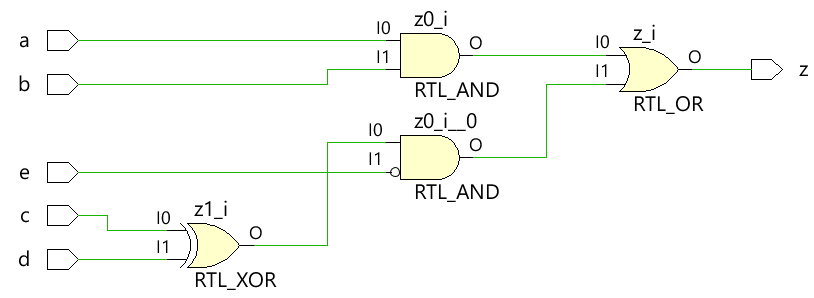
Der unten gezeigte Code implementiert eine einfache digitale kombinatorische Logik, die eine Ausgangsleitung z hat, die kontinuierlich mit einem assign angesteuert wird Anweisung zur Realisierung der digitalen Gleichung.
module combo ( 	input 	a, b, c, d, e,
								output 	z);

	assign z = ((a & b) | (c ^ d) & ~e);

endmodule
Das Modul combo wird unter Verwendung von Synthesewerkzeugen in das folgende Hardwareschema ausgearbeitet und es ist ersichtlich, dass die kombinatorische Logik mit digitalen Gattern implementiert wird.
Testbench
Die Testbench ist eine Plattform zur Simulation des Designs, um sicherzustellen, dass sich das Design wie erwartet verhält. Alle Kombinationen von Eingaben werden mit for zum Designmodul geleitet Schleife mit einer Verzögerungsangabe von 10 Zeiteinheiten, damit nach einiger Zeit der neue Wert an den Eingängen anliegt.
module tb;
	// Declare testbench variables
  reg a, b, c, d, e;
  wire z;
  integer i;

  // Instantiate the design and connect design inputs/outputs with
  // testbench variables
  combo u0 ( .a(a), .b(b), .c(c), .d(d), .e(e), .z(z));

  initial begin
  	// At the beginning of time, initialize all inputs of the design
  	// to a known value, in this case we have chosen it to be 0.
    a <= 0;
    b <= 0;
    c <= 0;
    d <= 0;
    e <= 0;

    // Use a $monitor task to print any change in the signal to
    // simulation console
    $monitor ("a=%0b b=%0b c=%0b d=%0b e=%0b z=%0b",
              a, b, c, d, e, z);

    // Because there are 5 inputs, there can be 32 different input combinations
    // So use an iterator "i" to increment from 0 to 32 and assign the value
    // to testbench variables so that it drives the design inputs
    for (i = 0; i < 32; i = i + 1) begin
      {a, b, c, d, e} = i;
      #10;
    end
  end
endmodule
Simulationsprotokoll ncsim> run a=0 b=0 c=0 d=0 e=0 z=0 a=0 b=0 c=0 d=0 e=1 z=0 a=0 b=0 c=0 d=1 e=0 z=1 a=0 b=0 c=0 d=1 e=1 z=0 a=0 b=0 c=1 d=0 e=0 z=1 a=0 b=0 c=1 d=0 e=1 z=0 a=0 b=0 c=1 d=1 e=0 z=0 a=0 b=0 c=1 d=1 e=1 z=0 a=0 b=1 c=0 d=0 e=0 z=0 a=0 b=1 c=0 d=0 e=1 z=0 a=0 b=1 c=0 d=1 e=0 z=1 a=0 b=1 c=0 d=1 e=1 z=0 a=0 b=1 c=1 d=0 e=0 z=1 a=0 b=1 c=1 d=0 e=1 z=0 a=0 b=1 c=1 d=1 e=0 z=0 a=0 b=1 c=1 d=1 e=1 z=0 a=1 b=0 c=0 d=0 e=0 z=0 a=1 b=0 c=0 d=0 e=1 z=0 a=1 b=0 c=0 d=1 e=0 z=1 a=1 b=0 c=0 d=1 e=1 z=0 a=1 b=0 c=1 d=0 e=0 z=1 a=1 b=0 c=1 d=0 e=1 z=0 a=1 b=0 c=1 d=1 e=0 z=0 a=1 b=0 c=1 d=1 e=1 z=0 a=1 b=1 c=0 d=0 e=0 z=1 a=1 b=1 c=0 d=0 e=1 z=1 a=1 b=1 c=0 d=1 e=0 z=1 a=1 b=1 c=0 d=1 e=1 z=1 a=1 b=1 c=1 d=0 e=0 z=1 a=1 b=1 c=1 d=0 e=1 z=1 a=1 b=1 c=1 d=1 e=0 z=1 a=1 b=1 c=1 d=1 e=1 z=1 ncsim: *W,RNQUIE: Simulation is complete.
Beispiel #2:Halbaddierer
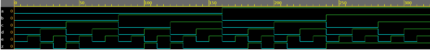
Das Halbaddierermodul akzeptiert zwei skalare Eingaben a und b und verwendet eine kombinatorische Logik, um die Ausgaben Summe und Übertragsbit Cout zuzuordnen. Die Summe wird durch ein XOR zwischen a und b getrieben, während das Übertragsbit durch ein UND zwischen den beiden Eingängen erhalten wird.
module ha ( input 	a, b,
						output	sum, cout);

	assign sum  = a ^ b;
	assign cout = a & b;
endmodule
Testbench
module tb;
	// Declare testbench variables
  reg a, b;
  wire sum, cout;
  integer i;

  // Instantiate the design and connect design inputs/outputs with
  // testbench variables
  ha u0 ( .a(a), .b(b), .sum(sum), .cout(cout));

  initial begin
  	// At the beginning of time, initialize all inputs of the design
  	// to a known value, in this case we have chosen it to be 0.
    a <= 0;
    b <= 0;

    // Use a $monitor task to print any change in the signal to
    // simulation console
    $monitor("a=%0b b=%0b sum=%0b cout=%0b", a, b, sum, cout);

    // Because there are only 2 inputs, there can be 4 different input combinations
    // So use an iterator "i" to increment from 0 to 4 and assign the value
    // to testbench variables so that it drives the design inputs
    for (i = 0; i < 4; i = i + 1) begin
      {a, b} = i;
      #10;
    end
  end
endmodule
Simulationsprotokoll ncsim> run a=0 b=0 sum=0 cout=0 a=0 b=1 sum=1 cout=0 a=1 b=0 sum=1 cout=0 a=1 b=1 sum=0 cout=1 ncsim: *W,RNQUIE: Simulation is complete.

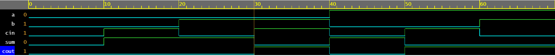
Beispiel #3:Volladdierer
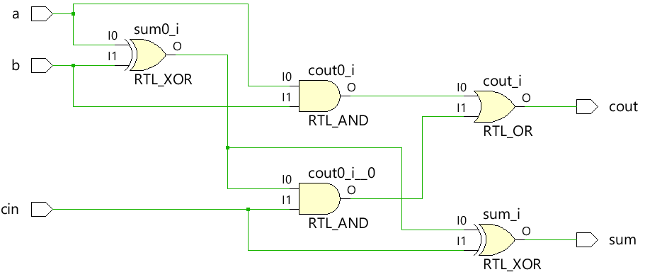
Ein Volladdierer kann unter Verwendung des oben gezeigten Halbaddierermoduls gebaut werden, oder die gesamte kombinatorische Logik kann unverändert mit assign angewendet werden Anweisungen zum Ansteuern der Ausgänge sum und cout.
module fa (	input 	a, b, cin,
						output 	sum, cout);

	assign sum  = (a ^ b) ^ cin;
	assign cout = (a & b) | ((a ^ b) & cin);
endmodule
Testbench
module tb;
  reg a, b, cin;
  wire sum, cout;
  integer i;

  fa u0 ( .a(a), .b(b), .cin(cin), .sum(sum), .cout(cout));

  initial begin
    a <= 0;
    b <= 0;

    $monitor("a=%0b b=%0b cin=%0b sum=%0b cout=%0b", a, b, cin, sum, cout);

    for (i = 0; i < 7; i = i + 1) begin
      {a, b, cin} = i;
      #10;
    end
  end
endmodule
Simulationsprotokoll ncsim> run a=0 b=0 cin=0 sum=0 cout=0 a=0 b=0 cin=1 sum=1 cout=0 a=0 b=1 cin=0 sum=1 cout=0 a=0 b=1 cin=1 sum=0 cout=1 a=1 b=0 cin=0 sum=1 cout=0 a=1 b=0 cin=1 sum=0 cout=1 a=1 b=1 cin=0 sum=0 cout=1 ncsim: *W,RNQUIE: Simulation is complete.
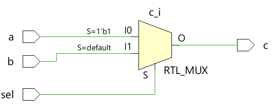
Beispiel Nr. 4:2x1-Multiplexer
Der einfache 2x1-Multiplexer verwendet einen ternären Operator, um zu entscheiden, welcher Eingang dem Ausgang c zugewiesen werden soll. Wenn sel 1 ist, wird der Ausgang von a gesteuert, und wenn sel 0 ist, wird der Ausgang von b gesteuert.
module mux_2x1 (input 	a, b, sel,
								output 	c);

	assign c = sel ? a : b;
endmodule
Testbench
module tb;
	// Declare testbench variables
  reg a, b, sel;
  wire c;
  integer i;

  // Instantiate the design and connect design inputs/outputs with
  // testbench variables
  mux_2x1 u0 ( .a(a), .b(b), .sel(sel), .c(c));

  initial begin
  	// At the beginning of time, initialize all inputs of the design
  	// to a known value, in this case we have chosen it to be 0.
    a <= 0;
    b <= 0;
    sel <= 0;

    $monitor("a=%0b b=%0b sel=%0b c=%0b", a, b, sel, c);

    for (i = 0; i < 3; i = i + 1) begin
      {a, b, sel} = i;
      #10;
    end
  end
endmodule
Simulationsprotokoll ncsim> run a=0 b=0 sel=0 c=0 a=0 b=0 sel=1 c=0 a=0 b=1 sel=0 c=1 ncsim: *W,RNQUIE: Simulation is complete.

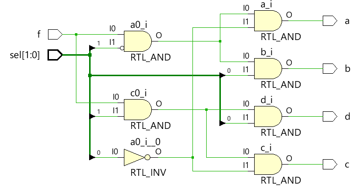
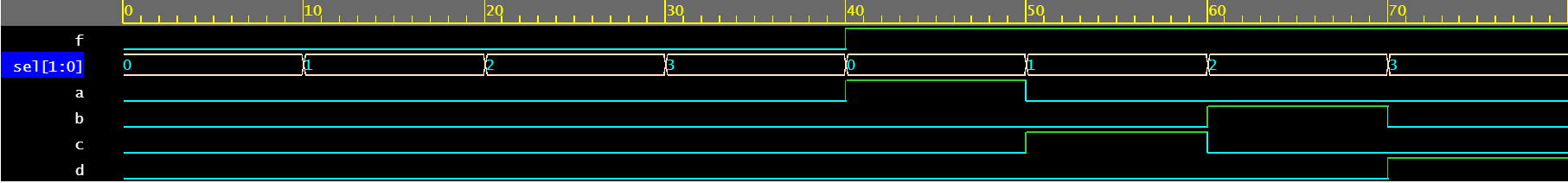
Beispiel #5:1x4 Demultiplexer
Der Demultiplexer verwendet eine Kombination aus sel- und f-Eingängen, um die verschiedenen Ausgangssignale zu treiben. Jedes Ausgangssignal wird von einem separaten assign angesteuert Aussage. Beachten Sie, dass es im Allgemeinen nicht empfohlen wird, dasselbe Signal von verschiedenen assign zu betreiben Aussagen.
module demux_1x4 (	input 				f,
										input [1:0]	 	sel,
										output 				a, b, c, d);

	assign a = f & ~sel[1] & ~sel[0];
	assign b = f &  sel[1] & ~sel[0];
	assign c = f & ~sel[1] &  sel[0];
	assign d = f &  sel[1] &  sel[0];

endmodule
Testbench
module tb;
	// Declare testbench variables
  reg f;
  reg [1:0] sel;
  wire a, b, c, d;
  integer i;

  // Instantiate the design and connect design inputs/outputs with
  // testbench variables
  demux_1x4 u0 ( .f(f), .sel(sel), .a(a), .b(b), .c(c), .d(d));

  // At the beginning of time, initialize all inputs of the design
  // to a known value, in this case we have chosen it to be 0.
  initial begin
    f <= 0;
    sel <= 0;

    $monitor("f=%0b sel=%0b a=%0b b=%0b c=%0b d=%0b", f, sel, a, b, c, d);

    // Because there are 3 inputs, there can be 8 different input combinations
    // So use an iterator "i" to increment from 0 to 8 and assign the value
    // to testbench variables so that it drives the design inputs
    for (i = 0; i < 8; i = i + 1) begin
      {f, sel} = i;
      #10;
    end
  end
endmodule
Simulationsprotokoll ncsim> run f=0 sel=0 a=0 b=0 c=0 d=0 f=0 sel=1 a=0 b=0 c=0 d=0 f=0 sel=10 a=0 b=0 c=0 d=0 f=0 sel=11 a=0 b=0 c=0 d=0 f=1 sel=0 a=1 b=0 c=0 d=0 f=1 sel=1 a=0 b=0 c=1 d=0 f=1 sel=10 a=0 b=1 c=0 d=0 f=1 sel=11 a=0 b=0 c=0 d=1 ncsim: *W,RNQUIE: Simulation is complete.
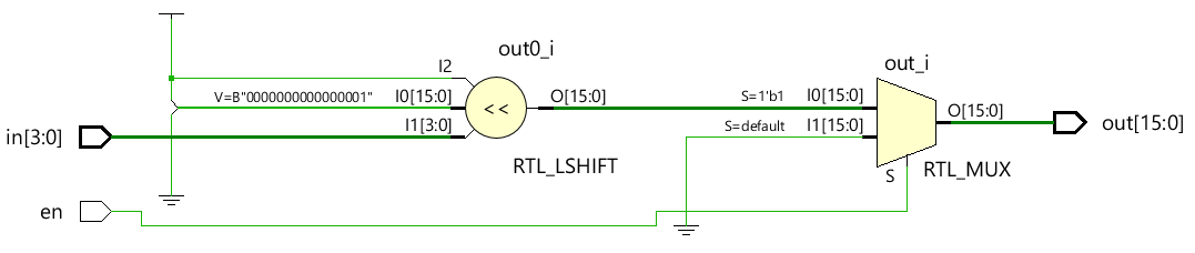
Beispiel #6:4x16-Decoder
module dec_3x8 ( 	input 					en,
									input 	[3:0] 	in,
									output  [15:0] 	out);

	assign out = en ? 1 << in: 0;
endmodule
Testbench
module tb;
  reg en;
  reg [3:0] in;
  wire [15:0] out;
  integer i;

  dec_3x8 u0 ( .en(en), .in(in), .out(out));

  initial begin
    en <= 0;
    in <= 0;

    $monitor("en=%0b in=0x%0h out=0x%0h", en, in, out);

    for (i = 0; i < 32; i = i + 1) begin
      {en, in} = i;
      #10;
    end
  end
endmodule
Simulationsprotokoll ncsim> run en=0 in=0x0 out=0x0 en=0 in=0x1 out=0x0 en=0 in=0x2 out=0x0 en=0 in=0x3 out=0x0 en=0 in=0x4 out=0x0 en=0 in=0x5 out=0x0 en=0 in=0x6 out=0x0 en=0 in=0x7 out=0x0 en=0 in=0x8 out=0x0 en=0 in=0x9 out=0x0 en=0 in=0xa out=0x0 en=0 in=0xb out=0x0 en=0 in=0xc out=0x0 en=0 in=0xd out=0x0 en=0 in=0xe out=0x0 en=0 in=0xf out=0x0 en=1 in=0x0 out=0x1 en=1 in=0x1 out=0x2 en=1 in=0x2 out=0x4 en=1 in=0x3 out=0x8 en=1 in=0x4 out=0x10 en=1 in=0x5 out=0x20 en=1 in=0x6 out=0x40 en=1 in=0x7 out=0x80 en=1 in=0x8 out=0x100 en=1 in=0x9 out=0x200 en=1 in=0xa out=0x400 en=1 in=0xb out=0x800 en=1 in=0xc out=0x1000 en=1 in=0xd out=0x2000 en=1 in=0xe out=0x4000 en=1 in=0xf out=0x8000 ncsim: *W,RNQUIE: Simulation is complete.

Verilog
- Tutorial - Schreiben von kombinatorischem und sequentiellem Code
- Schaltung mit Schalter
- Integrierte Schaltkreise
- Speicherprogrammierbare Steuerungen (SPS)
- Einführung in die Boolesche Algebra
- Arithmetik mit wissenschaftlicher Notation
- Fragen und Antworten mit einem Industrie-4.0-Lösungsarchitekten
- Überwachen der Temperatur mit Raspberry Pi
- Beispiele für Verilog-Gate-Level
- Verilog-Zeitformat