Eine Übersicht über elektrochemisch selbstorganisierte Titanoxid-Nanoröhren-Arrays:Synthese, Modifikationen und biomedizinische Anwendungen
Zusammenfassung
Durch anodische Oxidation gezüchtete Titanoxid-Nanoröhren haben die Materialwissenschaftsgemeinschaft durch ihre vielen einzigartigen und potenziellen Eigenschaften fasziniert, und die Synthese der Technologie befindet sich in einem ausgereiften Stadium. Die vorliegende Überprüfung konzentriert sich auf TiO2 . Nanoröhren, die durch selbstorganisierte elektrochemische Anodisierung aus einem Ti-Metallsubstrat gezüchtet wurden, was die Synthese dieser Art von selbstorganisierten Titanoxid-Nanoröhrenschichten und die Möglichkeit zur Beeinflussung der Größe, Form, des Ordnungsgrads und der kristallisierten Phasen durch die Anpassung der Anodisierung kritisch hervorhebt Parameter und das anschließende thermische Glühen. Die Beziehung zwischen Abmessungen und Eigenschaften des anodischen TiO2 Nanotube-Arrays werden vorgestellt. Der neueste Fortschritt und die Bedeutung der Forschung zum Bildungsmechanismus von anodischem TiO2 Nanoröhren werden kurz diskutiert. Außerdem werden wir die vielversprechendsten Anwendungen, die kürzlich in biomedizinischer Richtung berichtet wurden, und Modifikationen zeigen, die durch Dotieren, Oberflächenmodifizieren und thermisches Tempern zur Verbesserung der Eigenschaften von anodisch gebildetem TiO2 . durchgeführt wurden Nanoröhren. Zuletzt werden einige ungelöste Probleme und mögliche zukünftige Richtungen dieses Feldes aufgezeigt.
Einführung
Seit Anfang des 20. Jahrhunderts wird Titandioxid (TiO2 ) wurde als kommerzielle Produktion in Sonnenschutzmitteln, Farben, Sensoren, Photokatalyse, Solarzellen, elektrochromen Geräten, Wirkstoffabgabe usw. verwendet [1,2,3,4,5,6,7]. Das Phänomen, dass TiO2 kann die photogenerierten Elektron-Loch-Paare unter Lichtbestrahlung erzeugen, kann dabei helfen, Wasser in Sauerstoff und Wasserstoff aufzuspalten, was dazu beitragen kann, die Energiekrise in Zukunft als potenzieller Brennstoff zu lösen. Fujishima und seine Mitarbeiter berichteten zuerst über die photokatalytische Wasserspaltung an einem TiO2 Elektrode unter ultraviolettem (UV) Licht [8,9,10], und seitdem hat sich Titandioxid zu einer der am besten untersuchten Verbindungen in der Materialwissenschaft entwickelt. Unter allen Übergangsmetalloxiden weist es ein breites Spektrum funktioneller Eigenschaften wie chemische Inertheit, Korrosionsbeständigkeit und Stabilität, insbesondere die Verbesserung der Biokompatibilität [11], sowie elektrische und optische Eigenschaften auf [1]. Seit Iijima 1991 die Kohlenstoffnanoröhren entdeckte [12], die eine einzigartige Kombination zwischen Form und Funktionalität aufweisen und deren Eigenschaften direkt durch die Geometrie beeinflusst werden können, wurden enorme Anstrengungen auf dem Gebiet der Nanotechnologie unternommen, hauptsächlich in der chemischen, physikalischen und biomedizinischen Materialwissenschaft.
Obwohl das bisher am meisten erforschte Nanomaterial Kohlenstoff ist, hat eine andere Klasse von Nanoröhrenmaterialien, die normalerweise auf Übergangsmetalloxiden basieren, in den letzten 20 Jahren erhebliches Interesse auf sich gezogen. Der erste Versuch, anodisierte Titandioxid-Nanoröhren herzustellen, wurde von Assefpour-Dezfuly [13] unternommen, der eine alkalische Peroxidbehandlung gefolgt von einer elektrochemischen Anodisierung in einem chromsäurehaltigen Elektrolyten verwendete. Und da Zwilling et al. berichteten, dass sie 1999 die ersten selbstorganisierten Nanoröhrenschichten auf Ti-Substrat durch elektrochemische Anodisierung in fluorionenhaltigen Chromsäureelektrolyten erzeugten, hat sich das Feld enorm schnell ausgeweitet [14]. In den letzten zehn Jahren wurden mehr als 33.800 Artikel mit dem Stichwort „Titandioxid-Nanoröhren“ veröffentlicht. Abbildung 1 zeigt die Gesamtpublikation aufgeschlüsselt pro Jahr im Bereich TiO2 Nanoröhren und zieht einen Vergleich zwischen verschiedenen Synthesemethoden im Zeitraum 2002–2017, der nicht nur einen exponentiellen Wachstumstrend zeigt, sondern offensichtlich darauf hindeutet, dass das selbstorganisierte anodische TiO2 Nanotube-Arrays erhalten viel Aufmerksamkeit mit großem Potenzial und Vorteilen. In letzter Zeit haben Lee et al. hat einen umfassenden und aktuellen Überblick auf dem Gebiet der anodischen Titandioxid-Nanoröhren gegeben, der fast alle Aspekte einschließlich Wachstum, Modifikationen, Eigenschaften und Anwendungen mit einer kurzen Darstellung verschiedener Syntheseansätze abdeckte [15]. Im Vergleich zu anderen Herstellungsmethoden wie hydro/solvothermal [16,17,18] und templatunterstützten Methoden [19, 20] erweist sich die Direktoxidation als einfache Technik mit starker Durchführbarkeit, bei der die gewünschte kontrollierbare Nanostruktur über Größenanpassung, Form und Ordnungsgrad können durch Optimierung der Oxidationsparameter wie angelegtes Potential, Zeit, Temperatur, pH-Wert und Zusammensetzung des Elektrolyten erhöht werden [15]. Aufgrund der besonderen Geometrie stellen die selbstjustierten Oxid-Nanoröhren-Schichten mit hoch organisierter Struktur und Oberflächen-Volumen-Verhältnis einzigartige Eigenschaften dar, wie eine sehr hohe mechanische Festigkeit und die große spezifische Oberfläche, die sogar elektronische Eigenschaften wie hohe Elektronen Mobilitätsrate oder Quanten-Confinement-Effekte [15, 21]. Darüber hinaus ist die elektrochemische Anodisierung ein kostengünstiges Verfahren und nicht auf Titan beschränkt, sondern kann auch für andere Übergangsmetalle Hf [22], Zr [23], Nb [24], Ta [25], V [26] oder Legierungen geeignet sein TiAl [27] und TiZr [28]. Die vorliegende Überprüfung wird sich weiterhin auf TiO2 . konzentrieren Nanoröhren, die durch selbstorganisierte elektrochemische Anodisierung von einem Ti-Metallsubstrat gezüchtet wurden. Außerdem werden wir die Synthese dieser Art von selbstorganisierten Titandioxid-Nanoröhrenschichten und die Mittel zur Beeinflussung der Größe, Form, des Ordnungsgrades und der kristallisierten Phasen durch die Anpassung der Anodisierungsparameter und das anschließende thermische Tempern hervorheben, einschließlich vier verschiedener Generationen unterschiedlichen Elektrolyten und der definierten zweistufigen Anodisierung usw. Die Beziehung zwischen Abmessungen und Eigenschaften des anodischen TiO2 Nanotube-Arrays werden vorgestellt. Der neueste Fortschritt und die Bedeutung der Forschung zum Bildungsmechanismus von anodischem TiO2 Nanoröhren werden kurz diskutiert. Wir werden die vielversprechendsten Anwendungen, die kürzlich in biomedizinischer Richtung berichtet wurden, und Modifikationen zeigen, die durch Dotieren, Oberflächenmodifizieren und thermisches Glühen zur Verbesserung der Eigenschaften von anodisch gebildetem TiO2 . durchgeführt wurden Nanoröhren. Wir betrachten auch ungelöste Fragen und mögliche zukünftige Richtungen dieses Bereichs. Der Hauptabsatztext folgt hier direkt.
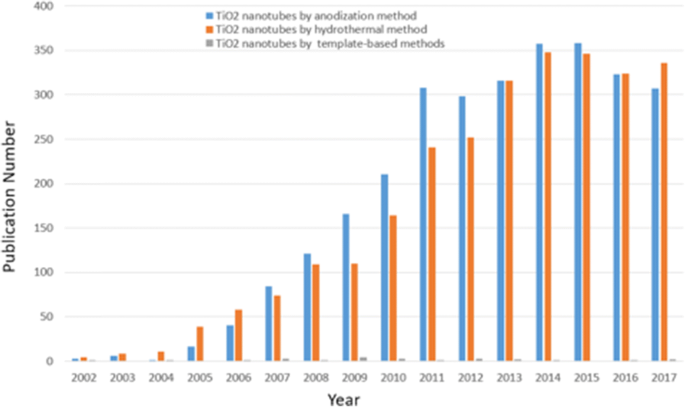
Forschungstrend. Die Anzahl der pro Jahr aufgeschlüsselten Veröffentlichungen in Bezug auf TiO2 Nanotubes differenziert nach verschiedenen Synthesemethoden von 2002 bis 2017. (Daten wurden aus dem Science Citation Index Expanded unter Verwendung von Titandioxid-Nanoröhren und Anodisierung oder hydrothermalen Methoden oder templatbasierten Methoden als Schlüsselwörter gesammelt)
Synthese von TiO2 Nanoröhren-Arrays durch elektrochemische Anodisierung
Während in den letzten Jahren viele verschiedene Formen von nanostrukturiertem Titandioxid, einschließlich Nanostäben, Nanopartikeln, Nanodrähten und Nanoröhren, erfolgreich entwickelt wurden [29,30,31], haben Nanoröhren aufgrund der einzigartigen selbstorganisierten Struktur mit einen großen Grenzflächenbereich und eine bequeme Steuerung der Größe und Form, die als besserer Kandidat auf oberflächenabhängige Anwendungen angewendet werden können. Es gibt eine Reihe exzellenter Übersichtsartikel [1, 2, 15, 32,33,34] zu den Eigenschaften von TiO2 Nanomaterialien, die mit verschiedenen Synthesemethoden kategorisiert werden. Die elektrochemische Anodisierung hat sich als eine der effektivsten Methoden erwiesen, um Titandioxid-Nanoröhren als relativ einfache und leicht automatisierbare Technologie zu erhalten. Wir werden die wichtigsten Techniken zur Herstellung von anodischem TiO2 . spezifizieren Nanoröhren unten.
Selbstorganisiertes anodisches TiO2 Nanoröhren-Arrays
Wie ausführlich untersucht, können die Titandioxid-Nanoröhrenschichten unter bestimmten festgelegten Umgebungsbedingungen gebildet werden. Die Oxidationsvorrichtung besteht aus drei Teilen:(I) einem Drei-Elektroden-System mit der vorbereiteten Ti-Folie als Arbeitselektrode, die durch sequentielle Beschallung in Aceton, Ethanol und entionisiertem Wasser entfettet wird, Platin als Gegenelektrode und normalerweise Ag/AgCl als Referenzelektrode (Abb. 2a), während manchmal die pH-Elektrode hinzugefügt wird, um die Endkonzentration von F − . zu erhalten und HF [35] oder ein anderes einfaches Zwei-Elektroden-System bestehend aus Ti-Folie als Anode und inerter Metallelektrode als Kathode (Abb. 2b) [36]; (II) im Allgemeinen Fluoridionen, Chloridionen, Chromionen, Bromidionen oder Perchlorat enthaltende Elektrolyte; und (III) eine Gleichstromversorgung. Es gibt zwei Hauptmerkmale, die von den Anodisierungsbedingungen der Bildung beeinflusst werden, die die vielversprechenden Anwendungen von Titandioxid-Nanoröhren beeinflussen:(I) Geometrie:Größe, Form, Ordnungsgrad, kristallisierte Phasen usw. und (II) Eigenschaften in chemischer, physikalischer und biomedizinische. Mit anderen Worten, über die Kontrolle der elektrochemischen Anodisierungsparameter (angelegtes Potenzial, Dauer der Anodisierung, Elektrolytsystem einschließlich der Konzentration der Fluorionen und Wasser im Elektrolyten, Elektrolyttemperatur, Elektrolyt-pH-Wert usw.), auf die genauer eingegangen wird im Abschnitt „Synthesis of TiO2 Nanotube Arrays by Electrochemical Anodization“) können verschiedene Titandioxid-Nanostrukturen hergestellt werden, wie z. B. ein flaches kompaktes Oxid [1], eine poröse Schicht [1, 36], ungeordnetes TiO2 Nanoröhrenschichten, die in Bündeln wachsen [37] oder schließlich ein hoch organisiertes regelmäßiges TiO2 Nanoröhren oder fortgeschrittene Nanoröhrenschicht:verzweigte Röhren [38], bambusartige [38, 39], doppelwandige [40], Nanolace [38] oder doppellagige [39] Strukturen, in denen Eigenschaften unterschiedlich gefunden werden können. Die Abbildungen 3 und 4 zeigen Bilder der Feldemissions-Rasterelektronenmikroskopie (FE-SEM) von typischen Beispielen eines solchen TiO2 Nanoröhren-Morphologien.
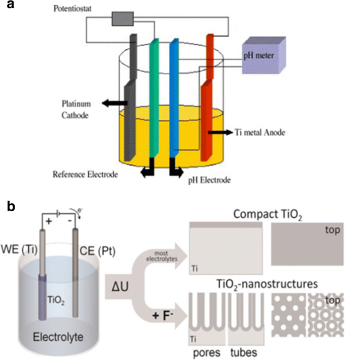
Schematischer Aufbau. a Illustrative Zeichnung eines Drei-Elektroden-Systems mit der präparierten Ti-Folie als Arbeitselektroden, Platin als Gegenelektrode und üblicherweise Ag/AgCl als Referenzelektrode, während die pH-Elektrode als pH-Meter dient. Reproduziert aus Ref.-Nr. [35]. b Illustrative Zeichnung eines einfachen Zwei-Elektroden-Systems bestehend aus Ti-Folie als Anode und inerter Metallelektrode als Kathode. Die Anodisierung führt unter verschiedenen Bedingungen zu einer unterschiedlichen anodisierten Oxidschicht. In den meisten neutralen und sauren Elektrolyten kann ein kompaktes Titandioxid gebildet werden. Wenn jedoch verdünnte Fluoridelektrolyte verwendet werden, werden nanotubuläre/nanoporöse Oxidschichten direkt auf der Metalloberfläche befestigt. Reproduziert aus Ref.-Nr. [36]
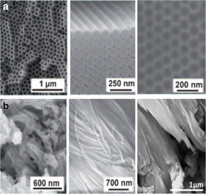
REM-Bilder von eloxiertem TiO2 Nanotube-Schichten durch verschiedene Anodisierungsprozesse von Ti. a Das hochgeordnete TiO2 Nanoröhren (in Draufsicht und Seitenansicht) werden in organischen Elektrolytsystemen mit selbstgeordneten Oberflächengrübchen (rechts) erhalten, die beim Entfernen der Röhrenschichten tatsächlich metallische Oberflächen sind. Reproduziert aus Ref.-Nr. [1]. b Das ungeordnete TiO2 Nanoröhren werden in Flecken auf der Oberfläche gezüchtet und durch eine ultraschnelle Anodisierungstechnik, die als Rapid-Breakdown-Anodisierung (RBA) bekannt ist, zu Bündeln in einem chloridhaltigen Elektrolyten verschmolzen. Reproduziert aus Ref.-Nr. [1] und [37]
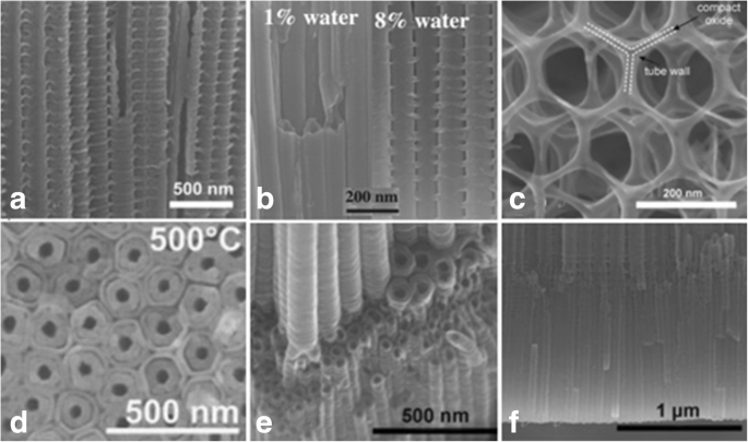
REM-Bilder von fortgeschrittenem TiO2 Nanoröhren-Morphologien. a Bambus-verstärktes TiO2 Nanoröhren werden unter spezifischen Wechselspannungsbedingungen (AV) in Ethylenglykol bestehend aus 0,2 mol/L HF mit einer Sequenz von 1 min bei 120 V und 5 min bei 40 V hergestellt. [38]. b Übergang von glattem zu bambusähnlichem TiO2 Nanoröhren können durch Anodisierung mit kontrollierter Wasserzugabe (Wassergehalt:1 bis 8 %) auf 0,135 M NH4 . induziert werden F/Ethylenglykol-Elektrolyt
wiedergegeben aus ref. [39]. c Die 2D-Nanolace-Strukturen werden unter Spannungszyklen im fluoridhaltigen Elektrolyten über einen längeren Zeitraum mit einer Sequenz von 50 s bei 120 V und 600 s bei 0 V erhalten. [38]. d Das doppelwandige TiO2 Nanoröhren werden durch Anodisierung von Ti in einem fluoridhaltigen Ethylenglykol-Elektrolyten bei 120 V nach Tempern bei 500 °C mit einer Heizrate von 1 °C s −1 . gezüchtet . Reproduziert aus Ref.-Nr. [40]. e Die verzweigten Nanoröhren können durch Spannungsstufen beobachtet werden, zuerst bei 120 V (6 h) und dann bei 40 V (2 h). Reproduziert aus Ref.-Nr. [38]. f Zu erkennen sind die doppellagigen Nanoröhren mit gleichen oder zwei unterschiedlichen Röhrendurchmessern. Reproduziert aus Ref.-Nr. [38]
(Derzeit TiO2 Nanoröhren-Arrays mit Röhrendurchmessern von 10 bis 500 nm, Schichtdicken von einigen hundert Nanometern bis 1000 µm und Wanddicken von 2 bis 80 nm sind erhältlich [15, 41].)
Es war vor zwei Jahrzehnten, als Masuda und Fukuda zum ersten Mal über hochgeordnetes poröses Aluminiumoxid durch Anpassung der Anodisierungsbedingungen auf ein Optimum berichteten [42]. Später bemühten sich die Forscher, ähnlich organisierte Strukturen auch für TiO2 . herzustellen Nanoröhren-Schichten. Und es gibt drei entscheidende Faktoren, die den Ordnungsgrad in anodischem TiO2 . beeinflussen Nanoröhren-Arrays (entsprechend Polygonen in den Schichten und der Standardabweichung des Röhrendurchmessers):das Ti-Substrat, die angelegte Spannung und die wiederholte Anodisierung [33, 43]. Es ist offensichtlich, dass für hochreines Material bei der höchstmöglichen Spannung unterhalb des dielektrischen Durchbruchs [33] und dem idealerweise hexagonalen selbstgeordneten TiO2 . weniger Fehler in der Anordnung erhalten werden können Nanoröhren wie in Abb. 5 gezeigt, können durch das Wachstum von Sekundärröhren signifikant verbessert werden [43]. Sophaet al. zeigten, dass Verunreinigungen die resultierenden unterschiedlichen Abmessungen und Anordnungen von Nanoröhren nach der zweiten Anodisierung stark beeinflussen [44]. Darüber hinaus haben sich die kristallographischen Orientierungen der Ti-Substratkörner als entscheidende Auswirkungen auf die Wachstumseigenschaften von TiO2 . erwiesen Nanoröhren-Arrays durch Elektronenrückstreubeugung (EBSD). Leonardi et al. fanden heraus, dass Nanoröhren nur mit einer Orientierung beobachtet werden können, die die Bildung eines Ventilmetalloxids auf den Körnern ermöglicht, das das Eindringen von Fluoridionen durch den Oxidationsfilm ermöglicht, wo 1 M (NH4 )H2 PO3 +0,5 Gew.-% NH4 F wurden als Elektrolyt verwendet [45]. In ähnlicher Weise berichteten Macak und Mitarbeiter, dass das Nanoröhrenwachstum auf Körnern im weit verbreiteten Elektrolyten auf Ethylenglykol-Basis im Vergleich zur Verwendung von wässrigen Elektrolyten, wie aus der letzten Literatur bekannt, nicht verzögert wird [46]. Auf dem polierten Ti-Blatt stellten sich Körner mit einer Orientierung von [0 0 0 1] oder nahe dieser als ideale Körner heraus, und die Verwendung von einkristallinem Ti mit idealer Orientierung wäre ein großer Fortschritt, um die gleichmäßigsten Nanoröhren-Arrays zu erhalten [46] .
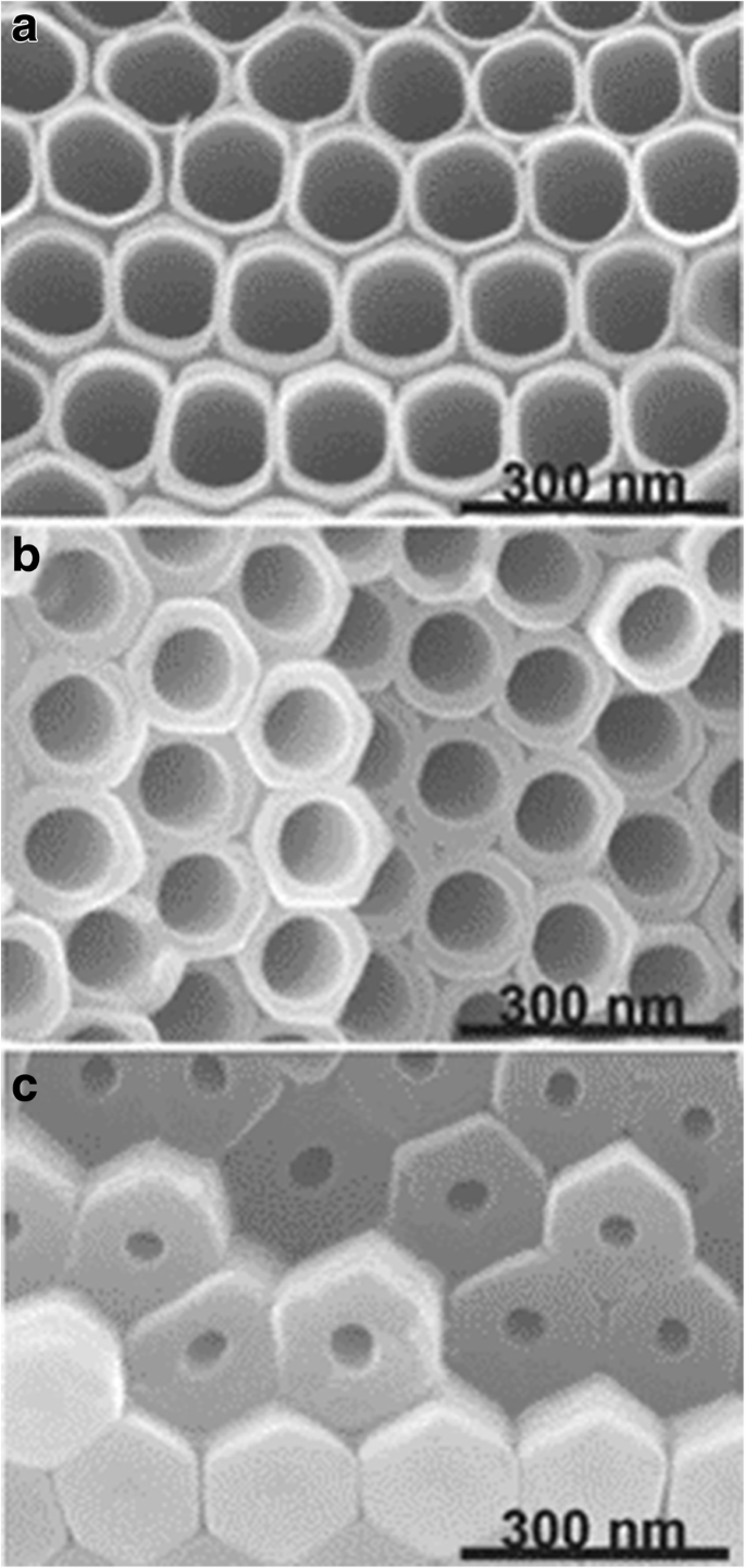
REM-Aufnahmen von TiO2 Nanoröhren. Die Nanoröhren werden in Ethylenglykol-Elektrolyten gebildet, die 0,27 M NH4 . enthalten F durch wiederholtes Anodisieren von Ti. Die Querschnitte werden oben in der Schicht, in der Mitte und unten in der Schicht aufgenommen. Reproduziert aus Ref.-Nr. [43]
Dennoch gibt es noch einige Mängel, die den Ordnungsgrad beeinflussen. In letzter Zeit wurde es durch das einheitliche Nanoprägen von Ti erweitert. Kondo et al. eine Durchsatzfertigung eines ideal geordneten anodischen TiO2 . ermittelt durch Nanoprägen einer Ti-Oberfläche oder einer zweischichtigen Probe mit einer Al-Schicht auf der Oberseite und der Ti-Schicht auf der Unterseite unter Verwendung einer Ni-Form mit geordneten Konvexitäten. Und das TiO2 Schichten konnten geordneter erzeugt werden, wobei die flachen Konkavitäten des vortexturierten Musters durch die anschließende Anodisierung in NH4 . als Initiationsstellen fungierten F Ethylenglykollösung [47, 48]. Genau folgend haben Sopha et al. zunächst eine durch Atomlagenabscheidung (ALD) hergestellte TiN-Schutzschicht auf ein Ti-Substrat aufbringen, bevor die Vortexturierung durch fokussierten Ionenstrahl (FIB) und die anschließende Anodisierung mit Ethylenglykol-Elektrolyt zu perfekt hexagonal angeordneten Nanoröhrenschichten mit einer Dicke von 2 μm, was die Nanoröhren nur auf das Wachstum an den gegebenen Initiationsstellen beschränken und die Anodisierungszeit ohne Defekte verlängern kann [49].
Bildungsmechanismus von anodischem TiO2 Nanoröhren
Anodische Oxidationstechnologie und Forschungen zum Bildungsmechanismus von anodischem TiO2 Nanotubes haben seit langem große Aufmerksamkeit in den unterschiedlichsten Disziplinen auf sich gezogen. Die Mechanismenforschung, über die Diggle 1969 über die Filme aus kompaktem anodischem Oxid und porösem anodischem Oxid berichtete [50], spielt auch heute noch eine äußerst wichtige Leitrolle. Eine bedeutende Anzahl neuerer Arbeiten zeigt, dass der Übergang von Poren zu Röhren gradueller Natur ist [1, 27, 36]; das vollständig theoretische Modell und die Begründung wurden jedoch nicht angegeben.
Die konventionelle feldunterstützte Auflösung (FAD) ist die akzeptabelste Theorie [1, 33, 51]. Das ist im Prozess der elektrochemischen Anodisierung, TiO2 Nanoröhren-Arrays werden durch Selbstorganisation von Titandioxid aufgrund von drei relativ unabhängigen Verfahren gebildet:elektrochemische Oxidation von Ti zu TiO2 , die durch ein elektrisches Feld induzierte Auflösung von TiO2 , und die durch Fluorionen induzierte chemische Auflösung von TiO2 , erreicht ein empfindliches Gleichgewicht. Als charakteristische Strom-Zeit-Kurve in Abb. 6 für fluoridhaltige Elektrolyte, die zur Bildung von Nanoröhrchen führen [51] und als typisches Bild, das helfen kann, den Bildungsprozess schematisch darzustellen [33] in Abb. 7 gezeigt, kann die Transiente unterteilt werden in drei verschiedene Stadien:(I) Im ersten Teil gibt es einen Stromabfall, verursacht durch ein neu gebildetes Barriereoxid, wenn die beiden Hauptprozesse, die Einwanderung von O
2−
Ionen in Richtung der Metall/Oxid-Grenzfläche und die Auswanderung von Ti
4+
Ionen in Richtung der Oxid/Elektrolyt-Grenzfläche ein Gleichgewicht erreichen. (II) Im zweiten Teil beginnt der Strom durch die zunehmende Oberfläche der Anode zeitverzögert wieder anzusteigen. Je kürzer die Verzögerung ist, desto höher ist die Fluoridkonzentration aufgrund der fluoridinduzierten Auflösung des gebildeten TiO2 , und Poren beginnen sich zufällig zu bilden, was sich später als die anfängliche Bildung von TiO2 . herausstellt Nanoröhren. (III) Dann erreicht der Strom einen stationären Zustand, wenn die Porenwachstumsrate an der Metalloxidgrenzfläche und die induzierte Auflösungsrate des gebildeten TiO2 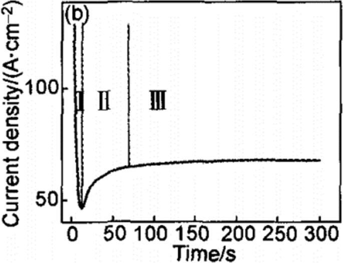
Typischer Strom-Zeit-Verlauf bei konstanter Spannung in fluoridhaltigen Elektrolyten. Der Transient kann in drei verschiedene Regionen unterteilt werden (I –III ). (Ich ) Im ersten Teil gibt es einen starken Stromabfall. (II ) Im zweiten Teil beginnt der Strom zeitversetzt wieder anzusteigen. (III ) Im dritten Teil erreicht der Strom einen stationären Zustand, der aus Lit. reproduziert wird. [51]
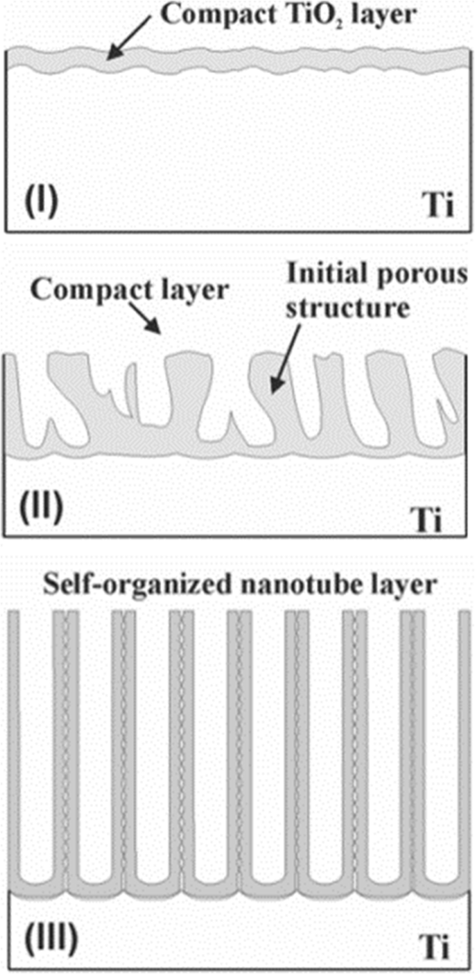
Der Bildungsprozess von TiO2 Nanoröhren-Arrays. Die Bildung von TiO2 Nanoröhren-Arrays können in drei verschiedene morphologische Stadien unterteilt werden (I –III ). (Ich ) Es bildet sich ein Barriereoxid. (II ) Die Oberfläche wird lokal aktiviert und die Poren beginnen zufällig zu wachsen. (III ) Selbstorganisierte Nanoröhrenschicht wird gebildet, reproduziert aus Lit. [33]
Diese Theorie kann jedoch das Phänomen der Trennung in Röhrchen im Gegensatz zu einer nanoporösen Struktur noch nicht eindeutig erklären, und Fahim et al. beobachteten, dass es unter geeigneten Spannungen möglich ist, Titandioxid-Nanoröhren in Schwefelsäurelösung ohne Fluoridionen zu erhalten, wobei in diesem Fall die I-t-Kurve der oben diskutierten ähnelte [52]. Wie Houser und Hebert betonten, wurden Wachstumsmechanismen noch nicht entwickelt, um die quantitativen Beziehungen zwischen dem Prozess der porösen Titandioxidmembran und der I-t-Kurve zu erklären [53]. Da die Interpretation nicht überzeugend genug ist, erscheinen in letzter Zeit neue Punkte über den Mechanismus, wie z. B. das Modell der viskosen Strömung und das Wachstumsmodell zweier Strömungen. In Bezug auf diese Mechanismen zeigt eine Übersicht [51] viele Einschränkungen für die traditionelle feldunterstützte Auflösungstheorie und gibt einige Erklärungen zu den neuesten Fortschritten und der Bedeutung der Forschung zum Modell der viskosen Strömung und des Wachstumsmodells von zwei Strömen.
Der Einfluss von Anodisierungsbedingungen auf Geometrie und Eigenschaften
Die Zusammensetzung und Konzentration der Elektrolyte haben einen signifikanten Einfluss auf die Bildung von Nanoröhren-Arrays. Entsprechend der unterschiedlichen verwendeten Elektrolyte gliedert sich die Entwicklung grundsätzlich in drei Phasen:Tabelle 1 fasst die Anodisierungsbedingungen und Abmessungen des resultierenden TiO2 . zusammen Nanotube-Arrays in den drei Generationen, die bisher von verschiedenen Forschungsgruppen untersucht wurden.
Die erste Generation:wässrige Elektrolyte auf Flusssäure (HF)-Basis
Der Meilenstein ist, dass Gong et al. präsentierten erstmals die einheitlichen Titandioxid-Nanoröhren-Arrays durch anodische Oxidation von Ti in HF-basierten wässrigen Elektrolyten [54]. In wässrigen HF-Lösungselektrolyten, bei denen der pH-Wert relativ niedrig ist, was eine hohe Konzentration an Wasserstoffionen bedeutet, wird die chemische Auflösung von TiO2 durch Fluorionen induzierte spielt die dominierende Rolle im Anodisierungsprozess [55]. Bei der Bildung von Titandioxid-Nanoröhren wurde in kurzer Zeit ein dynamisches Gleichgewicht erreicht, und daher wurde die maximal erreichbare Nanoröhrenlänge auf etwa 0,5 µm beschränkt [54,55,56].
Die zweite Generation:gepufferte Elektrolyte
In der nachfolgenden Arbeit, um die chemische Auflösung zu reduzieren und die Rohre zu verlängern, haben Cai et al. zeigten, dass durch Zugabe schwächerer Säuren wie KF oder NaF zu einer gepufferten Lösung und Einstellen des pH-Wertes auf schwach sauer (pH =4,5) mit Schwefelsäure oder Natronlauge Nanoröhren von ca. 4,4 µm Länge erreicht werden [57]. Der pH-Wert beeinflusst die Hydrolyse der Titanionen, die das elektrochemische Ätzen und die chemische Auflösung stören. Cai et al. wies auch darauf hin, dass niedrigere pH-Werte kürzere, aber saubere Nanoröhrchen erzeugen und höhere pH-Werte zu längeren Nanoröhrchen, aber unerwünschten Ablagerungen führen [57]. Mit steigendem pH-Wert nimmt die Hydrolysegeschwindigkeit zu, was wiederum die chemische Auflösung verlangsamt, was zu längeren Nanoröhren führt, während alkalische Lösungen für das Wachstum von Nanoröhren nicht geeignet sind [57, 58]. Es wurde von Macak et al. gezeigt, dass in neutralem NaF-Elektrolyt bei richtiger Spannung viel längere Nanoröhren erhalten werden konnten als in sauren Lösungen. [58]. Bei einer bestimmten Spannung in einem fluoridhaltigen Elektrolyten konnten durch Einstellen des pH-Gradienten die erforderlichen Seitenverhältnisse und Schichtdicken erreicht werden [59].
Die dritte Generation:polare organische Elektrolyte
Elektrolyte wie Glycerin [59], Dimethylsulfoxid [60], Formamid oder Diethylenglykol [61, 62], Ethylenglykol [41, 63], die Fluoridspezies wie NH4 . enthalten F, NaF und KF erscheinen nach und nach. Macak und Mitarbeiter übernahmen die Führung bei der Verwendung von viskosem Glycerin-Elektrolyt zur Herstellung von Titandioxid-Nanoröhren-Arrays mit einer Dicke von etwa 7 µm und einem durchschnittlichen Röhrendurchmesser von 40 nm [59]. Es wird gezeigt, dass TiO2 . mit einem höheren Seitenverhältnis Nanoröhren können in einem solchen polaren organischen Elektrolyten gezüchtet werden, da der pH-Wert des Elektrolyten richtig eingestellt wird und die chemische Auflösung des Titandioxids reduziert wird [64]. Pauloseet al. geformte Nanoröhren mit einer Länge von ungefähr 134 μm, hergestellt unter Verwendung von Ethylenglykol mit 0,25 Gew.-% NH4 F bei einem Anodisierungspotential von 60 V für 17 h [60]. Kurz darauf mehr als 250 μm dickes TiO2 Nanotube-Arrays wurden von Albu [65] beschrieben. Der Wassergehalt spielt dabei eine doppelte Rolle:Er ist für die Bildung von Titandioxid unabdingbar, beschleunigt aber auch die chemische Auflösung [63]. Daher ist es erforderlich, den Effekt des Wassergehalts auf eine minimale Signifikanz zu reduzieren, um die Dicke und den Ordnungsgrad des TiO2 . zu erhöhen Nanoröhren-Arrays. Im Allgemeinen ist die Begrenzung des Wassergehalts auf weniger als 5 % der Schlüssel zur erfolgreichen Herstellung sehr langer Nanoröhren [60], und eine Mindestmenge an Wassergehalt (0,18 Gew.-%) ist erforderlich, um gut organisierte Titandioxid-Nanoröhren zu bilden [66]. Es wurde berichtet, dass mit der Zugabe von Wasser die aufgezeichnete Stromdichte abnahm, die in wasserfreier Ethylenglykollösung am höchsten war [66]. Pauloseet al. erstmals über die Bildung von selbstorganisierten hexagonalen Titandioxid-Nanoröhren-Arrays mit einer Länge von ungefähr 1000 μm bei 60 V für 216 h in Ethylenglycol mit 0,6 Gew.-% NH4 . berichtet F und 3,5 % Wasser [41]. Ein weiteres auffälliges Phänomen ist, dass bei niedrigem Wassergehalt glatte Rohrwände wachsen, während bei höherem Wassergehalt Rippen an den Seitenwänden entstehen, wie in Abb. 4b gezeigt [59, 67]. Als mit Abstand am häufigsten verwendete Elektrolytart führt Ethylenglykol, das Wasser und Fluoridionen enthält, immer zu doppelwandigen Nanoröhrenstrukturen (Abb. 4d) [40, 68, 69, 70], während die innere Schicht durch a geeignete Glühbehandlung gefolgt von einem einfachen chemischen Ätzprozess. Nach dem Entfernen der Innenschale ermöglichen die aufgeweiteten Rohre eine schichtweise Dekoration mit Nanopartikeln unter Verwendung eines repetitiven Ansatzes auf Basis von TiCl4 -Hydrolyse [71]. Während einwandige Röhren in Farbstoffsolarzellen (DSSCs) eine deutlich verbesserte Leitfähigkeit und Elektronentransportzeit zeigten [71, 72], bei denen die Dicke der gesamten Röhre im Wesentlichen gleich ist und die Innenhülle nicht mehr erscheint, haben Mirabolghasemi et al. machte einen Vergleich zwischen den doppelwandigen und einwandigen Rohren und präsentierte gewünschte einwandige Rohre mit einer Zugabe von Dimethylsulfoxid (DMSO) zu Elektrolyten mit 1,5 M H2 O und 0,1 M NH4 F [72].
Kürzlich wurde berichtet, dass nicht-fluoridbasierte Elektrolyte TiO2 . wachsen lassen Nanotube-Arrays, die als vierte Synthesegeneration angesehen werden können, einschließlich Salzsäure, Wasserstoffperoxid, Perchlorsäurelösungen und deren Mischungen [73, 74]. Allama und Grimes beschrieben gut entwickelte Nanoröhren-Arrays mit 300 nm Länge, 15 nm Innendurchmesser und 25 nm Außendurchmesser, die in einem wässrigen Elektrolyten mit 3 M Salzsäure (HCl) bei Oxidationsspannungen zwischen 10 und 13 V erhalten wurden Hinzufügen einer geringen Konzentration von H3 PO4 führte zu einem Wechsel von Nanoröhren zu Stäbchen. Sie schlugen ferner vor, dass sie in HCl-haltigen Elektrolyten bei einer Konzentration von niedriger oder höher als 3 M keine selbstorganisierten Nanoröhren-Arrays erzielen konnten [73]. Allama fand heraus, dass die Zugabe von Wasserstoffperoxid zu der salzsäurehaltigen wässrigen Lösung eine mögliche Methode sein könnte, um die Titandioxid-Nanoröhren zu verlängern, die nach einer dickeren Oxidschicht eine stark oxidierende Eigenschaft besitzen, was zeigt, dass Fluoridionen erfolgreich durch Chloridionen im Wachstum ersetzt werden können von Nanoröhren-Arrays [74]. Außerdem wurden in den letzten Jahren ionische Flüssigkeiten ohne Zugabe von freien Fluoridspezies als eine andere Art von Lösungsmittelsystemen für Titandioxid-Nanoröhren behandelt [75, 76].
Neben den Standardparametern ist die Geometrie der resultierenden Nanoröhren von der wiederholten Verwendung von Elektrolyt abhängig (der „gebrauchte Lösungseffekt“). Im Vergleich zu den Röhren, die mit frischen Lösungen erhalten wurden, zeigten Einmallösungen eine Zunahme der Nanoröhrchenlänge und eine bessere Qualität, wobei die erzielte Nanoröhrchen-Wachstumsrate für Einmallösungen bei 60 V und mehr konstant höher ist [77] und a leicht unterschiedliches, aber unterscheidbares Stromtransientenverhalten konnte festgestellt werden [66]. Darüber hinaus wurde in der zweimal verwendeten Lösung aufgrund der Verarmung an F – . keine Nanoröhrenstruktur, sondern ein Oxidfilm erhalten Arten [78]. Sopha et al. untersuchten verschiedene Altersgruppen von Elektrolyten auf Ethylenglykolbasis auf die Morphologie von TiO2 Nanoröhren, die zeigen, dass die Arrays in älteren Elektrolyten niedrigere Seitenverhältnisse aufweisen [79].
Angewandtes Potenzial
Die Anodisierungsspannung ist der kritische Faktor, der die Rohrdurchmesser steuert [80, 81]. Die Dimension der Nanoröhren-Arrays kann einfach durch Anlegen des geeigneten Spannungsbereichs, der als Potentialfenster bezeichnet wird, über die Elektrode vorhergesagt werden [67]. Bei einer niedrigen Spannung tritt eine geringere Auflösung des elektrischen Felds auf, wodurch TiO2 . gebildet wird Nanoröhren mit kleinerem Durchmesser. Wenn die Spannung zu niedrig ist, wird das TiO2 Die Schicht wird kompakt, aber es kann keine Nanoröhrenstruktur beobachtet werden. Im Gegensatz dazu wird eine schwammartige poröse Struktur beobachtet, wenn die Spannung zu hoch ist. With controllable voltage, the diameter of the nanotubes is proportional to the voltage [81]. Furthermore, studies show that the range of voltage forming nanotubes is also related to the electrolyte system. In aqueous electrolytes, the potential window should be controlled from 10 to 25 V, which in organic electrolytes is much wider between several volts and some hundred volts. Wang and Lin found out the fact that in aqueous electrolytes, the anodization potential exhibits significant influence on the growth of TiO2 nanotube arrays, which exhibited slight influence in non-aqueous electrolytes in this regard [82]. The voltage dependence has a significant reduction in non-aqueous electrolytes which is attributed to a large extent to the low conductivity of organic electrolytes [83, 84].
The Duration on Anodization
The duration of anodization affects the nanotubes mainly in two aspects:(I) the formation of the tubes or not and (II) the length of the tubes. That is, in the early stage of the anodization, a compact TiO2 film is formed. If the duration is too short to reach an equilibrium in reaction, the regular nanotube array cannot be achieved instead of a disordered porous layer [67]. With increasing the anodization time, porous structure gradually grows deeper and converts into the TiO2 nanotubular array [1, 33, 51]. If other electrochemical parameters are kept unchanged, increase in the nanotube length is observed over time while no significant effect on diameter and tube wall thickness until a steady-state situation occurs [67, 85, 86]. However, due to the decrease of the F − concentration in the electrolyte, where the ion transport rate decreased, the growth rate of nanotubes is reduced. After reaching a stable condition between tube growth at the bottom and chemical/electrochemical dissolution at the top, we will find no further increase in length of the nanotubes [87]. As time continues to go, pipe orifice becomes an irregular polygon resulting in TiO2 spikes and coverings which can be seen on the surface of the TiO2 nanotube arrays [36]. It is worth mentioning that enlightened by the success of aluminum-repeated anodization for self-organized porous alumina [88], the two-step anodization of titanium for such a highly ordered hexagonally packed nanostructure of titania has appeared [43, 77, 89,90,91]. After the first-step anodization, the first nanotube layer from the Ti foil should be removed ultrasonically or by using an adhesion tape which leads to a surface where the remaining Ti is covered by comparably ordered dimples. Researches have shown that the former treatment helps to avoid potential mechanical damage to the Ti surface and also improve the structural uniformity of the TiO2 nanotubes to a great extent [77, 90, 91]. In the second anodization step, the pretreated Ti foil would be used as anode again with or without changes in parameters of oxidation conditions. It is subsequently found that the highly ordered and vertically oriented titania nanotubes, have greater potential in such fields as photocatalysis [77], photoelectriochemical activity [92, 93], and biological interaction with cells [94] than the disordered nanotubular titania.
Electrolyte Temperature
Temperature restricts the growth and quality of titania nanotube arrays, directly affecting the rate of oxide growth, length, and wall thickness of the structure [64, 95]. Wang and Lin first reported the effect of electrolyte temperature in both aqueous and non-aqueous electrolyte on anodic oxidation of titanium [82]. In aqueous electrolyte, with the temperature increasing, a slight diminish in the internal diameters was observed while the external diameters remained the same [68]. The reason may be the dissolution induced by electrical field and fluoride ions are similar while the oxide formation rate is higher than that at lower temperature. In non-aqueous electrolyte containing fluoride ions, the outer nanotube diameter was found to be largely increased by the increasing electrolyte temperature [82]. This may be because at lower temperature, the ion mobility of fluorine in some viscous electrolyte is further inhibited, leading to much slower dissolution of newly formed titania, which subsequently lead to a smaller nanotube diameter. As chemical dissolution rate increases, surface of TiO2 nanotubes arrays can easily produce excessive corrosion, resulting in lodging nanotubes and agglomeration. Therefore, the appropriate bath temperature for stable TiO2 nanotube arrays is at room temperature [82, 95, 96].
Modification of Nanotubes Properties
Increasing applications of TiO2 nanotubes as a novel semiconductor are closely related to its photoelectriochemical (PEC) performance; however, they are sometimes prevented by two fundamental drawbacks:(I) the wide band gap (3.0 eV for the rutile phase and 3.2 eV for the anatase phase) can only absorb ultraviolet light, which accounts for less than 10% of the sunlight [97], resulting in low average utilization ratio of solar energy and (II) the low electrical conductivity cannot efficiently transfer photogenerated carries. At the same time, the photoelectrons and vacancies can be easily recombined, thus making low electron mobility rate or quantum confinement effects [98]. Hence, post-treatment of TiO2 nanotubes is the key to improve the performance of its materials and related devices successfully. Considerable researches have been reported on modified methods to reduce the recombination of photogenerated electron-hole pair rate, speed up the electron transfer rate, and enhance the photoelectriochemical activity of TiO2 nanotubes. The research of the methods for the improvement of the photoelectriochemical properties of TiO2 nanotubes will be reviewed, including thermal annealing, doping, and surface modification. As for promising modification in biomedical fields, we will present in the application section.
Thermal Annealing
The crystallinity of the nanotube arrays and their conductivity, lifetime of charge carrier, and photoresponse depend mainly on the thermal annealing temperature and atmosphere [99, 100]. The as-prepared TiO2 nanotubes above are amorphous in nature but can be annealed to anatase or rutile phase, or mixtures of both phases relying on the specific temperature [1, 3, 40, 92, 100]. It is demonstrated that amorphous nanotube layers grown in a glycerol-based electrolyte containing fluoride ions have low photocurrents and an incident photon-to-electron conversion efficiency (IPCE) below 5% due to lots of structural defects while anatase phase nanotubes exhibit an IPCE value up to 60% thus attracting more interest to applications such as dye-sensitized or perovskite solar cells [93]. As well in mixed water-glycerol electrolyte with F − , Das et al. stated their points that if the self-organized TiO2 nanotube arrays with thickness about 1 μm were annealed around 300–500 °C, the anatase phase of TiO2 as the most preferred crystalline structure could be observed. The single anatase structure of nanotubes with the best photoelectriochemical properties and the lowest resistivity could be fabricated when annealed at 400 °C. At temperature higher than 600 °C, a track of typical rutile appeared and with a further increase in annealing temperature the percentage and quality of the rutile phase increased [92]. It should be noted that in Jaroenworaluc’s work, rutile phase was detected in anodic nanotube layers grown in aqueous NaF/Na2 SO4 with thickness of approximately 1.5 μm at 500 °C heat treatment and became the dominant phase at 600 °C. Whereas at 550 °C, partial nanotubes began to break down [101]. It begins to cause the collapse of the entire nanostructure formed in aqueous NaF/Na2 SO4 with the continuous increase of temperature (800–900 °C) or the extended annealing time [3]. While for extended temperature, the crystalline structure of the nanotubes completely converts to rutile phase at above 900 °C [3]. Some researchers demonstrated a loss of the typical single-walled nanotube layers morphology when the annealed temperature rose above 580 °C [102]. Besides the whole annealing process especially the heating rate controls, the morphological structures of the entire nanotube arrays [40]. The double-walled nanotube layers prepared from ethylene glycol (containing less than 0.2 wt% H2 O), with the addition of HF and H2 O2 , have such a high stability that can keep their structure intact until temperature is higher than 900 °C with a heating rate of 1 °C s −1 . However, the double-walled nanotubes begin to collapse as soon as the temperature reaches 500 °C when the heating rate is 25 °C s −1 . Most extraordinarily, with the high speed of 50 °C s −1 the entire separated nanotubes fuse into a highly ordered porous membrane [40]. Xiao et al. obtained crystallized titania nanotubes arrays with calcination in different gases like dry nitrogen, air, and argon indicating nanotubes in dry nitrogen appeared to have enhanced electrochemical and photoelectrical properties who also found out that with the increasing temperature internal diameter decreased while wall thickness increased at the expense of nanotubes length [103].
As shown in Fig. 8, the conductivity along the TiO2 nanotubes with three different thickness is strongly affected by annealing temperature. Smallest resistance is observed at about 350–450 °C when the amorphous nanotube arrays are totally converted into anatase layers [99]. And it is evident to see that specific resistivity increases with thicker nanotube arrays which can be shown more clearly in the inset in Fig. 8. Furthermore, calcination temperature is responsible for the decrease in the length of the anatase TiO2 nanotubes. As shown in Fig. 9a, increment of temperature between 300 and 500 °C causes the as-prepared nanotube arrays slightly changing in thickness from 13.6 to 12.6 μm. When annealing temperature continuously increases to 600 °C, the average length of the nanotubes decrease dramatically to 6.6 μm. Figure 9b shows conversion from anatase TiO2 to rutile phase TiO2 occuring at 500 °C when the rutile barrier layer is formed on the bottom of the TiO2 nanotube arrays along the anatase nanotubes by consuming the bottom layer if the annealed temperature is further increased. This leads to a length decrease and corresponding photocatalytic activity decline [104].
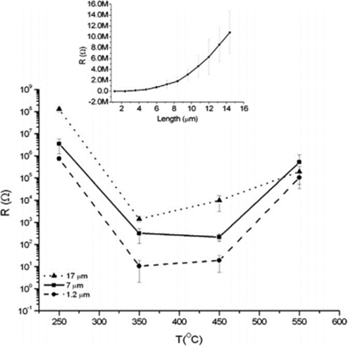
Electrical resistance as a function of the annealing temperature for the different nanotube layer thicknesses. The curve shows electrical resistance measurement for different titania nanotube arrays grown in ethylene glycol based electrolyte containing HF and water at different temperature and the influence of thickness on resistance. The inset shows more details about the relationship between the thickness of the nanotube arrays annealed at 250 °C and their specific resistivity. Reproduced from ref. [99]
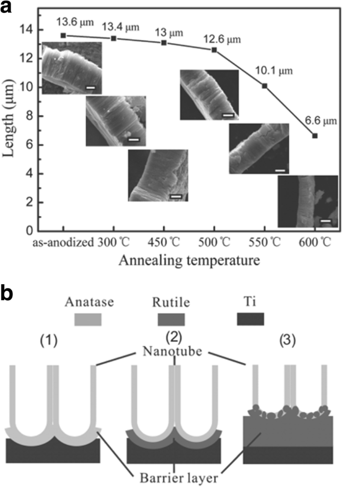
Evolution of titania nanotube arrays at different calcination temperatures. The electrolyte was ethylene glycol containing 0.3 wt% ammonium fluoride and 5 vol% distilled water. a The decrease in the thickness of titania nanotube arrays at different annealing temperature from 300 to 600 °C. The insets are corresponding SEM images and the scale bar is 5 μm. b The schematic of crystallization process of anodic titania nanotubes annealed at (1) 450 °C, (2) 500 °C, and (3) 600 °C in air. Reproduced from ref. [104]
Doping
Doping ions or atoms into titania lattice, a substitution within the lattice either at Ti 4+ or O 2− sites, on the one hand, changes the lattice constants and bond energy. On the other hand, it is beneficial to the separation between photogenerated electron and hole pair, which in turn adjusts the band gap and improves the photoelectrochemical performance of nanotubes [15]. The impurity doping has been commonly applied to extend the light absorption onset of TiO2 nanotubes by either introducing subbandgap states or adjusting its bandgap width [105]. Lately, co-doping approach has been proposed as a more efficient way to reduce the band gap and adjust energy band level in favor of photoelectriochemical reactions [106, 107]. There are various kinds of doped-elements and preparation methods, and Table 2 summarizes some methods and the doping effects of doped titania nanotubes.
The most typical doped TiO2 nanotubes are as follows:
- i.
Metal-doped TiO2 nanotubes such as Nb [107], Fe [108], Cu [109], Cr [110], Zr [111], Zn [112], and V [113]
- ii.
Non-metal-doped TiO2 nanotubes such as N [105], F [114], B [115], C [116], S [117], and I [118]
- iii.
Co-doped TiO2 nanotubes such as N–Ta [105], N–Nb [107], and C–N–Ni [119]
Choiet systematically studied the photoreactivities of 21 metal ion-doped quantum-sized TiO2 doping with Fe, Mo, Ru, Os, Re, V, and Rh significantly increases quantum efficiency, while Co and Al doping decreases the photoreactivity [120]. Momeni et al. recently obtained Fe-TiO2 nanotube (Fe-TNT) composites using different amounts of irons to decorate anodically formed TiO2 nanotubes with potassium ferricyanide as the iron source, indicating that Fe doping efficiently accelerates the photocatalytic performance for water splitting [108]. Not limited to transition metals, other elements including N [105], F [114], B [115], C [116], S [117], and I [118] are successfully explored. Nitrogen-doped TiO2 nanotubes turns out to be a promising path to narrow the band gap energy with enhanced photocurrent response in the visible light and the tube length influences the magnitude of conversion efficiency [121, 122]. Kim and co-workers proved that TaOxNy layer-decorated N-TNT (N-doped TiO2 nanotubes) as dual modified TNTs have significantly improved both visible (3.6 times) and UV (1.8 times) activities for water splitting [105]. At present, more researches are aimed at co-doping which exhibits remarkable synergistic effect causing a significant improvement on photoelectriochemical properties. Chai et al. grew Gd–La co-doped TiO2 nanotubes by an ultrasonic hydrothermal method, enhancing visible light photocatalysts [123]. Cottineau et al. modified titania nanotubes with nitrogen and niobium to achieve co-doped nanotubes with noticeably enhanced photoelectriochemical conversion efficiency in the visible light range [107]. Nevertheless, the mechanism for increasing photoconductivity and synergistic effect of various elements on co-doping remains a further study.
Surface Modification
Surface modification means decoration on surface of TiO2 nanotube arrays with nanoparticles (metal, semiconductors, and organic dyes). Nanowire arrays can also be fabricated by electrodeposition into titanium oxide nanotubes [124]. TiO2 nanotube is a semiconductor with a wide band gap, which can only absorb ultraviolet light [97, 125]. Any other nanomaterials which possess a narrow band gap or can absorb the visible light can be used as a sensitizer for titania nanotubes. Silver nanoparticles can be decorated on the tube wall by soaking the titania nanotube arrays in AgNO3 solutions and photocatalytically reducing Ag + on a TiO2 surface by UV illumination [126]. Ag/TiO2 nanotubes show a significantly higher photocatalytic activity and good biological performance compared with neat TiO2 nanotubes [126, 127]. Some compositions such as graphene oxide GO [128], CdS [129], CdSe [130], and ZnFe2 O4 [131]. can be modified on TiO2 nanotube arrays. Lately, GO have attracted much scientific interest in nanoscale devices and sensors which is easy to combine with nanostructure materials to compose some compounds. Titania nanotubes fabricated by anodization in water-ethylene glycol electrolyte consisting of 0.5 wt% ammonium fluoride (NH4 F) can be incorporated with GO by cyclic voltammetric method, which achieve higher photocatalytic activity and more effective conversion efficiency (GO-modified vs pure nanotubes =26.55%:7.3%) of solar cell than unmodified TiO2 nanotubes [128]. Semiconductor composite is a method improving the performance of titania nanotubes via, in some specific way, combining two kinds of semiconductors with different band gap [132]. Yang et al. decorated CdSe nanoparticles on the surface of TiO2 nanotubes by applying an external electric field to accelerate CdSe nanoparticles in nanochannels resulting in a material with more stable and higher photoresponse to visible light. Furthermore, the degeneration rate of anthracene-9-carbonxylic acid when exposed to the green light irradiation indicating that CdSe dominates the photocatalytic process under visible light [130].
Besides, other oxide nanoparticle deposition such as WO3 [133] or TiO2 [134] onto TiO2 nanotubes by the hydrolysis of a chloride precursor also turns out to augment the surface area and improve the solar cell efficiency. Another very effective approach is to consider organic dyes as sensitizers for TiO2 nanotubes to improve its optical properties [135]. Lately, atomic layer deposition (ALD) becomes an established procedure to modify TiO2 nanotube layers. ALD appears to be a very uniform and precisely controllable deposition process to functionalize nanotubes in conformably coating the surface of the nanotube layers with one atomic layer after another of a secondary material, such as Pd [136], ZnO [137], Al2 O3 [138], CdS [139], or TiO2 [140].
Biomedical Applications
Historically, the mentioned milestones were reported on the fabrication of titania nanotube arrays contributing to widen the promising applications over the past 20 years in the areas ranging from anticorrosion, self-cleaning coatings, and paints to sensors [141,142,143], dye-sensitized and solid-state bulk heterojunction solar cells [144,145,146], photocatalysis [147, 148], eletrocatalysis, and water photoelectrolysis [149, 150]. They also outperform in biomedical directions as biocompatible materials, toward biomedical coatings with enhanced osseointegration, drug delivery systems, and advanced tissue engineering [15, 135, 141, 142, 151]. In the following section, we will give an overview of current efforts toward TiO2 nanotubes biomedical applications. Titania nanotubes possess good biocompatibility as they show some antibacterial property, low cytotoxicity, good stability, and cytocompatibility including promoting adhesion, proliferation, and differentiation of osteoblast and mesenchymal stem cells (MSCs) with a high surface area-to-volume ratio and controllable dimensions [152,153,154,155].
However, Ti products have inadequate antibacterial ability and efforts have been made to improve their antibacterial properties such as modifications on titania nanotubes for biomedical applications like bioimplant [126, 156].
Biological Coatings And Interactions with Cells
A number of in vitro and in vivo studies have demonstrated that MSCs, osteoblasts and osteoclasts show size-selective response which means the effect of size holds an important position in cell interaction where the optimized size for cell adhesion, proliferation, growth, and differentiation is ranging from 15 to 100 nm [153, 157, 158]. Particularly, it was demonstrated that the TiO2 nanotubes with a diameter of 70 nm was the optimal nanoscale geometry for the osteogenic differentiation of human adipose-derived stem cells (hASCs) [159]. Smith et al. reported increased dermal fibroblasts and decreased epidermal keratinocyte adhesion, proliferation, and differentiation on TiO2 nanotube arrays (diameter 70–90 nm, length 1–1.5 μm) [160]. As shown in Fig. 10, Peng et al. found that nanotubular surface preferentially promoted proliferation and function in endothelial cells (EC) while decreased in vascular smooth muscle cell (VSMC) by measuring EdU, a thymidine analog which is incorporated by proliferating cells [161]. Furthermore, it is pointed out that surface wettability of the TiO2 nanotube layers is recognized as a critical factor for cell behavior which can be adjusted by changing the diameter of the nanotubes. That is to say, water contact angles can be altered without changing the surface chemistry [158]. To get further understanding of the effect of TiO2 nanotube layers to bone-forming cells as well as stem cells response, Park et al. seeded green fluorescent protein-labeled rat MSCs on TiO2 nanotube layers with six different diameters (15, 20, 30, 50, 70, and 100 nm), resulting in cell activity that is sensitive to nanoscale surface topography with a maximum in cell activity obtained for tube diameters of approximately 15–30 nm. Such lateral spacing exactly corresponds to the predicted lateral spacing of integrin receptors in focal contacts on the extracellular matrix, forcing clustering of integrins into the closest packing, resulting in optimal integrin activation. While tube diameters larger than 50 nm, severely impaired cell spreading, adhesion, and spacing of 100 nm may lead to the cell apoptosis [94]. Besides adjusting the size of the nanotubes, surface modification loaded with bioactive factors should be highlighted, in which case biomedical properties can be further optimized. In the case of bone implants, hydroxyapatite (HA) formation is important for osseointegration. Recent works have shown hydroxyapatite nanocrystalline coating onto the nanotubular TiO2 results in further enhanced osseointegration with strong adhesion and bond strength, and a drastic enhancement of deposition rate is observed [162, 163]. Nanotubular TiO2 surface can greatly enhance the natural apatite growth rate in simulated body fluid (SBF) compared with flat surfaces [10, 164]. The alkaline-treated TiO2 nanotubes with NaOH solutions are more bioactive in SBF, where sodium titanate can significantly accelerate nucleation and the growth of HA formation presenting a well-adhered bioactive surface layer on Ti due to its larger surface area and promoted mechanical interlocking between HA and TiO2 nanotubes [165, 166]. Electrodeposited with hydroxyapatite, higher adhesion of TiO2 nanotubes has been described in the literature by means of adhesive tape test and the live/dead cell staining study which is essential for early bone formation [166]. The results also showed that at the length of 560 nm the highest adhesion of HA surface on the nanotubes is observed. Also the nanotube surface can indeed strengthen Collagen type I expression in vivo experiment which is considered to be a basic initial bone matrix protein in bone formation [167]. Moreover, annealing of the amorphous nanotubes to anatase or a mixture of anatase and rutile was found to be an important factor in the apatite formation process [164].
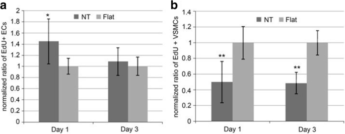
Ratio of EdU positive a ECs and b VSMCs on flat or nanotube substrate. It is normalized by the average proportion of positive cells on flat surfaces on day 1 and 3. Data is presented as average ± standard deviation. *p < 0.05, **p < 0.01 versus same day flat control, n = 6 reproduced from ref. [161]
Drug Delivery and Antibacterial Ability
Furthermore, the tubular nature of TiO2 in biomedical devices may be exploited as gene and drug delivery carriers with living matter due to its high surface area, controllable pore, and self-ordered structure [1, 15]. When the orthopedic bioimplant is placed into the bone defect, persistent and chronic infection is one of the most common and serious complications associated with biomedical implantation [16, 168]. Certain dimension and crystallinity may be useful to prevent bacteria adhesion and promote bone formation. The thermal annealing has decreased the number of bacteria adhering to the Ti surface. It could be in part because heat treatment removes the fluorine content which has a tendency to attract bacteria. The research also indicates that nanotubes with 60 or 80 nm in diameter decrease the number of live bacteria as compared to lower diameter (20 or 40 nm) nanotubes [169, 170].
Bauer et al. loaded epidermal growth factor (EGF) and bone morphogenetic protein-2(BMP-2) onto the TiO2 nanotubes surface by covalent attachment. They observed positive influence on the behavior of MSCs on 100-nm nanotube arrays where cell count was at much higher levels compared to the untreated one [171]. Lately, titania nanotubes loaded with antibiotics contribute to suppressing bacterial infections. As gentamicin sulphate (GS) is mostly widely used with highly water solubility, Feng et al. loaded titania nanotubes with GS through physical adsorption and cyclic loading which can treat many types of bacterial infections [172]. Zhang et al. fabricated titania nanotubes loaded with vancomycin to investigate the increasing biocompatibility and obvious antibacterial effect on Staphylococcus aureus [173]. However, systemic antibiotics in clinical will bring many side effects. The release of antibiotics from the nanotubes is too fast to maintain the long-term antibacterial ability, and the use of antibiotics may develop resistant strains [126, 168, 174]. Ensuring a constant release rate becomes a crucial but difficult part in the field of drug delivery. In strategies like surface modification, controlling the dimension of nanotube arrays, biodegradable polymer coating have been employed to solve the issue [21]. Drug release of several drugs such as antibiotics or growth factors from titania nanotube arrays can be adjusted by varying their diameters and lengths [152, 175, 176]. Feng et al. covered a thin film comprising a mixture of GS and chitosan on GS-loaded titania nanotubes and showed a controlled release of the drug providing sustained release effects to a certain extent [172]. Titania nanotube arrays as drug nanoreservoirs on Ti surface for loading of BMP-2 were fabricated by Hu et al. and then further covered with gelatin/chitosan multilayers to control the release of the functional molecule meanwhile maintain the bioactivity for over 120 h via a spin-assisted layer-by-layer assembly technique which is mainly based on electrostatic interactions between polyanions and polycations as well as promote osteoblastic differentiation of MSCs [177]. Lai et al. successfully fabricated Chi/Gel multilayer on melatonin-loaded TiO2 nanotube arrays to control the sustained release of melatonin and promote the osteogenic differentiation of mesenchymal stem cells [178]. Karan et al. synthesized titania nanotubes loaded with the water-insoluble anti-inflammatory drug indomethacin and modified lactic-co-glycolic acid on surface as a polymer film in order to extend the drug release time of titania nanotubes and produce favorable bone cell adhesion properties, with reduced burst release (from 77 to> 20%) and extended overall release from 4 days to more than 30 days [152]. As previous study reported that surface treatment of implants with N -acetyl cysteine (NAC) may reduce implant-induced inflammation and promote faster bone regeneration [179], Lee et al. examined the feasibility of N -acetyl cysteine-loaded titania nanotubes as a potential drug delivery system onto an implant surface, and the data indicates the enhanced osseointegration and the value of the small animal model in assessing diverse biological responses to dental implants. Besides, TiO2 nanotube arrays are suitable for loading inorganic agents like Ag, Sr, and Zn to obtain long-term antibacterial ability and osseointegration [126, 180,181,182]. Ag nanoparticles have been incorporated into TiO2 nanotube arrays previously with satisfactory small possibility to develop resistant strains, a broad-spectrum antibacterial property, low cytotoxicity, and good stability by immersion in a silver nitrate solution followed by ultraviolet light radiation [126]. Zhang et al. demonstrated that a series of porous TiO2 coatings with different concentrations of silver had significant inhibition effect on Escherichia coli and Staphylococcus aureus . Besides, only with the optimum amount of silver can the coatings retain the antibacterial effect but without any measurable cytotoxicity to cells [183]. Due to cytotoxicity observed by the excessive release of Ag + subsequently, titania nanotube arrays with Ag2 O nanoparticles embedded in the wall are prepared on Ti by TiAg magnetron sputtering and anodization in order to get slower and more controllable silver ion release [184]. That is because the TiO2 barrier is surrounded thereby minimizing the cytotoxicity induced by burst or large Ag + release.
Similar to Ag, Zn possesses antibacterial and anti-inflammation properties, and osteogenesis induction [185,186,187]. Huo et al. produced anodic TiO2 nanotube arrays at 10 V and 40 V (NT10 and NT40) incorporated with Zn by hydrothermal treatment at 200 °C for 1 and 3 h (NT10-Zn1, NT10-Zn3, NT40-Zn1, and NT40-Zn3) in Zn containing solutions, followed by annealing at 450 °C for 3 h in air. NT40-Zn3 has the largest Zn loading capacity and releases more Zn compared with other samples. The amounts of Zn released diminish gradually with time and nearly no Zn can be detected 1 month later except sample NT40-Zn3 (Fig. 11). The NT-Zn samples present different antibacterial ability. It is evident that NT40-Zn3 and NT10-Zn3 effectively kill more adherent bacteria as well as surrounding planktonic bacteria in the early stage. Figure 12a describes a synergistic effect of both released and surface incorporated Zn while Fig. 12b explains the effect of the released Zn [181].
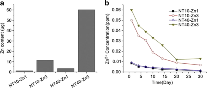
a Total amounts of Zn incorporated into the NT-Zn samples for the 1 cm 2 coatings and b non-cumulative Zn release profiles from NT-Zn into PBS. Reproduced from ref. [181]
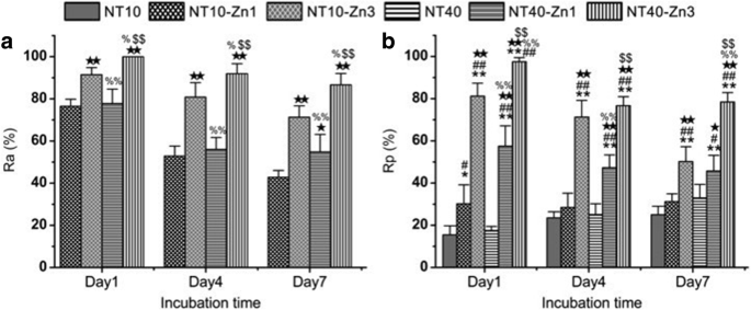
a Antibacterial rates versus adherent bacteria on the specimen (Ra) and b antibacterial rates against planktonic bacteria in the medium (Rp) *, **p < 0.05 and 0.01 vs NT10; # , ## p < 0.05 and 0.01 vs NT40; ★ , ★★ p < 0.05 and 0.01 vs NT10-Zn1; % , %% p < 0.05 and 0.01 vs NT10-Zn3; $ , $$ p < 0.05 and 0.01 vs NT40-Zn1. Reproduced from ref. [181]
Conclusions
This review presents the historical developments and traditional formation mechanism of titania nanotube arrays grown by electrochemical anodization as well as the approaches to influence and modify morphology in order to improve their performances. We also focus on current efforts toward TiO2 nanotubes applications in biomedical directions. Those steady progresses have demonstrated that TiO2 nanotubes are playing and will continue to play an important role in material science, but there are still some aspects needed to be further improved.
- 1.
The synthesis of TiO2 nanotube arrays is already comparatively mature so far in fact, but how to simplify the technology for the purpose of large-scale production in industry with extending practical operability and how to precisely control nanotube geometry efficiently by varying the anodic parameters so as to obtain optimized properties have yet to be further investigated.
- 2.
The formation mechanisms of anodic TiO2 nanotubes have gradually become a hotspot of research due to their unique structure and excellent performances but the exact mechanism remains controversial. Conventional FAD explains the growth process and the porous structure of TiO2 nanotubes, but the combination of viscous flow model and growth model of two currents can give a comprehensive explanation to the growth process. Notably, the validity of oxygen evolution resulting from electronic current has much room for investigation.
- 3.
Modification is key for improving performances of titania nanotube arrays. Thus, we need to explore more methods for modification and take full advantage of the self-organized nanostructure. Through self-assembling inorganic, organic, metallic, and magnetic nanoparticles into or onto the tubes as nanocomposites with broad spectral response to visible light, high quantum efficiency, and stabilizing properties, applications could be widened. Currently, ALD appears to be an option to coat the titania nanotube layers homogenously and precisely from the bottom to the tube mouth, resulting in many advanced functionalities of the newly prepared nanotube layers. Nevertheless, further optimization of the ALD process toward coatings and inner fillings is demanded.
- 4.
TiO2 nanotube researches in biomedical directions are still in their infancy and have a long distance to go in clinical use. The biological reaction between cells and titania nanotubes has to develop from cellular level to molecular level and from morphological changes to molecular alterations. It has been shown that adhesion, spreading, and growth of osteoblast and mesenchymal stem cells strongly depends on nanotube diameter, so the regularity and principle of this phenomenon as well as other factors affecting cells’ behaviors need to be further explored.
Abkürzungen
- ALD:
-
Atomic layer deposition
- BMP-2:
-
Bone morphogenetic protein-2
- DMSO:
-
Dimethyl sulfoxide
- DSSCs:
-
Dye-sensitized solar cells
- EBSD:
-
Electron Backscatter Diffraction
- EC:
-
Endothelial cells
- EdU:
-
A thymidine analog
- EGF:
-
Epidermal growth factor
- FAD:
-
Conventional field-assisted dissolution
- FE-SEM:
-
Field-emission scanning electron microscopy
- Fe-TNTs:
-
Fe-doped TiO2 nanotubes
- FIB:
-
Focused ion beam
- GO:
-
Graphene oxide
- GS:
-
Gentamicin sulphate
- HA:
-
Hydroxyapatite
- hASCs:
-
Adipose-derived stem cells
- IPCE:
-
Incident photon-to-electron conversion efficiency
- MSCs:
-
Mesenchymal stem cells
- NAC:
-
N -Acetyl cysteine
- N-TNT:
-
N-doped TiO2 nanotubes
- PEC:
-
Photoelectriochemical
- SBF:
-
Simulated body fluid
- UV:
-
Ultraviolet
- VSMC:
-
Vascular smooth muscle cell
Nanomaterialien
- 4 Verwendungen von Hafnium | Die Anwendungen von Hafnium und Hafniumlegierungen
- Multifunktionale Goldnanopartikel für verbesserte diagnostische und therapeutische Anwendungen:Eine Übersicht
- Fortschritte und Herausforderungen fluoreszierender Nanomaterialien für die Synthese und biomedizinische Anwendungen
- Graphen- und Polymerverbundstoffe für Superkondensatoranwendungen:ein Rückblick
- Auf dem Weg zu TiO2-Nanofluiden – Teil 2:Anwendungen und Herausforderungen
- Die Wirkung von Kontakt-Nichtgleichgewichtsplasma auf die strukturellen und magnetischen Eigenschaften von Mn Х Fe3 − X О4 Spinellen
- TiO2-Nanoröhren-Arrays:Hergestellt durch weiche-harte Schablone und die Korngrößenabhängigkeit der Feldemissionsleistung
- Vergleichende Studie der elektrochemischen, biomedizinischen und thermischen Eigenschaften natürlicher und synthetischer Nanomaterialien
- Frässpindel und die bemerkenswerten Anwendungen
- 9 Arten von Gewindeschneidwerkzeugen und die Anwendungen


