Winzige Seltenerd-Fluorid-Nanopartikel aktivieren das Wachstum von Tumorzellen über elektrische polare Wechselwirkungen
Zusammenfassung
Lokalisierte extrazelluläre Interaktionen zwischen Nanopartikeln und Transmembransignalrezeptoren können das Wachstum von Krebszellen durchaus aktivieren. Hier, winziger LaF3 und PrF3 Nanopartikel in DMEM+FBS-Suspensionen stimulierten das Tumorzellwachstum in drei verschiedenen humanen Zelllinien (A549, SW837 und MCF7). Größenverteilung von Nanopartikeln, Aktivierung von AKT- und ERK-Signalwegen und Lebensfähigkeitstests wiesen auf eine mechanische Stimulation der Ligandenadhäsionsbindungsstellen von Integrinen und EGFR über eine synergistische Wirkung eines Ensembles von winzigen Nanopartikeln (< 10 nm) hin. Während Nanopartikel winziger Größe gut mit der Aktivierung von EGFR in Verbindung gebracht werden können, bleibt das Zusammenspiel von Integrinen mit Nanopartikeln ein vielschichtiges Problem. Ein theoretisches Motiv zeigt, dass innerhalb der erforderlichen pN-Kraftskala jede Ligandenadhäsionsbindungsstelle durch ein winziges dielektrisches Nanopartikel über elektrische Dipolwechselwirkung aktiviert werden kann. Die Größe des aktiven Nanopartikels blieb durch die Menge der Oberflächenladungen auf der Ligandenadhäsionsbindungsstelle und dem Nanopartikel sowie durch den Trennungsabstand zwischen ihnen festgelegt. Die polare Komponente der elektrischen Dipolkraft blieb umgekehrt proportional zur zweiten Potenz der Nanopartikelgröße, was zeigt, dass nur dielektrische Nanopartikel winziger Größe das Wachstum von Krebszellen über elektrische Dipolwechselwirkungen stimulieren könnten. Die Arbeit trägt dazu bei, verschiedene Zytoskelett-Stress-Modi von Krebszellen zu erkennen.
Hintergrund
Die Tumorgenese ist ein mehrdimensionales Thema, das genomische Veränderungen mit sich bringt. Es wird auch durch Zell-Extrazelluläre Matrix-(ECM)-Interaktionen zwischen Gerüsten und Zytoskelett-Strukturen aktiviert [1,2,3,4], die durch Stress auf Mechanosensoren, ähnlich wie Integrine, durch mehrteilige zelluläre Kräfte, die die genomische Programmierung verändern können, exprimiert werden [5]. Die Interaktionen der Tumormikroumgebung mit ECM-Gerüsten aktivieren normalerweise die fokalen Adhäsionsproteine der Zellmembran und Transmembransignalrezeptoren (TSR), epidermale Wachstumsfaktorrezeptoren (EGFR), vaskuläre endotheliale Wachstumsfaktoren (VEGFR) oder Nervenwachstumsfaktorrezeptoren (NGFR). Die Mechanosensoren regulieren das Tumorzellwachstum über eine Signalübertragung zwischen der extrazellulären aktiven Domäne der Zellen [6,7,8,9] und den intrazellulären F-Aktin-Filamenten, indem sie eine Lawine von Phosphorylierungsreaktionen auslösen.
Konformationsänderungen von Proteinen und Anregung von TSR-Wegen erfordern, dass die aktivierende Kraft im pN-Kraftbereich liegt und sicherlich unter dem nN-Wert [10]. Neben zufälliger mechanischer Belastung und aktiver chemischer Affinitätsstärke kann die Bindungseffizienz (Bindungsstärke) zwischen Nanopartikeln (NPs) und den Proteinen der Zellmembran entweder über kurz- oder weitreichende elektrisch polare oder andere Arten dispersiver Wechselwirkungen moduliert werden. Auf der begrenzten Oberfläche von NPs kann nur eine bestimmte Anzahl von Proteinen lange genug angelagert werden, um biologisch aktiv zu sein [11], und es wurde erkannt, dass räumlich begrenzte lokale Interaktionen mit dem biologischen Milieu für eine Reihe von divergierenden Zellfunktionen verantwortlich sind Routen [12]. Folglich signalisieren die Signaltransaktionswege der Protein-NPs-Interaktion Sicherheitsprobleme für NPs [11, 13].
Da entweder eine günstige oder eine negative Reaktion in Zellen von NPs typspezifisch ist [11], sollte der Zusammenhang zwischen NPs und biologischen Markierungen von Fall zu Fall hergestellt werden [14, 15].
Widersprüchliche Ergebnisse von Tumorzellen, die NPs ausgesetzt wurden, entweder hinsichtlich der ablativen oder der Tumorwachstumseffizienz oder der variablen Toxizitätsniveaus von NPs [16, 17], decken die Sicherheitsprobleme ebenfalls auf. Trotz der Fortschritte fehlt es heute jedoch an Wissen über die spezifischen Wege, über die NPs mit eukaryontischen Zellen interagieren, was die Identifizierung eines universellen NP-therapeutischen Ansatzes ausschließt. Da NPs unterschiedlicher Größe und verschiedene Oberflächenchemien normalerweise zelluläre Reaktionen ablenken, einschließlich der NPs-Membranrezeptor-Bindung und der TSR-Aktivität, hängt die Toxizität von NPs mit der Morphologie der Tenside, dem elektrischen Ladungszustand, der Konzentration und Zusammensetzung von Proteinen und Nanomaterialien in ECM . zusammen [18,19,20,21] und schließlich die Stärke der molekularen Bindung zwischen NPs und den Zellphänotypen [22].
Frühere Studien an Melanomen und Zervixkarzinomen, die Silika, Gold-NPs und Kohlenstoff-Nanoröhrchen ausgesetzt waren, haben erkannt, dass die Größe der Nanopartikel das Wachstum von Tumorzellen selektiv aktiviert [23,24,25,26,27]. Die Korrelation zwischen TSR-Signalen in der humanen SK-BR-3-Krebszelllinie und der Größe modifizierter Gold- und Silber-NPs zeigte, dass, obwohl NPs mit einer Größe von 2–100 nm die Signaltransduktion wieder herstellten, ein immenser Unterschied in der apoptotischen Aktivität erzielt wurde, wenn Zellen mit 40 –50 nm große NPs [26]. Kürzlich wurde auch vorgeschlagen, dass eine Änderung der Größe von Gold-NPs von 5 auf 40 nm die Wachstumsraten der A549- und 95D-Krebszelllinien möglicherweise optimiert. Insbesondere hemmten NPs mit einer Größe von 5 nm jegliche Proliferation beider Zelltypen, während NPs mit einer Größe von ~10 nm keinen Einfluss auf das Zellwachstum hatten [27]. Ebenso wurden A549- und THP-1-Zellen SiO2 . ausgesetzt NPs zeigten eine größenabhängige Zytotoxizität sowie 15 nm große NPs wurden auch mit hohen Zytotoxizitätsniveaus korreliert. Im Gegensatz dazu wiesen NPs mit einer Größe von 60 nm eine geringere Toxizität auf. Schließlich steigerten 200 nm große NPs das Stammzellwachstum durch ERK1/2-Aktivierung, während 2–4 μm große NPs verschiedene Signaltransduktionswege aktivieren konnten [28]. Kleine NPs konjugieren den EGFR und schalten die Signalübertragungswege der Proteinkinase B (AKT) und der extrazellulären signalregulierten Kinase (ERK) ein, die das Zellwachstum entzünden.
Seltenerd-Nanopartikel (RE-NPs) können auch mit spezifischen Domänen wie Metallionen-abhängigen Adhäsionsstellen (MIDAS), Anpassung an MIDAS (ADMIDAS), synergistischen Metallionen-Bindungsstellen (SyMBS) und Ligandenadhäsions-Bindungsstellen (LABS) interagieren. , befindet sich in der αν β3 Untereinheit oder andere Integrine-Untereinheiten [29, 30].
Ebenso bringen RE-NPs einen zusätzlichen Grad an Geschmeidigkeit in der Interaktion von Tumor-NPs mit sich [31,32,33,34]. Während Ceroxid-NPs (Nanoceria) eine schützende Wirkung gegen Zellschäden durch verschiedene Radikale zeigten [35], steigerten niedrige Konzentrationen modifizierter Ceroxid-NPs die Proliferation von Hepatomzellen stark, indem sie die Apoptose über die Aktivierung von AKT/ERK-Signalwegen reduzieren [36]. Typischerweise ist ein die Zelle umgebendes Ensemble von NPs für zytoskelettalen Stress verantwortlich und steht gleichermaßen für chemische, nanothermodynamische (Hill) [37], entropische oder elektrische Dipolwechselwirkungen zwischen NPs und Mechanosensoren ein. Bis jetzt bleibt jedoch ein Verständnis der Wechselwirkungen zwischen NPs, TSRs und Zellen vage und nicht verfügbar.
Grundsätzlich sollte der stark ionische Charakter von RE-Verbindungen die Mechanosensoren von Zellen über elektrische Wechselwirkungen stimulieren. Da RE-Ionen in verschiedenen Anwendungen weit verbreitet sind, ist es außerdem wichtig, ihren potenziellen Beitrag zum Tumorzellwachstum zu untersuchen, um geeignete Protokolle zum Schutz der öffentlichen Gesundheit zu implizieren. Lanthanfluorid (LaF3 .) ) und Praseodymfluorid (PrF3 ) werden in Leuchtstofflampen, Strahlungsfarbgläsern, Faseroptiken, Emailanwendungen und Elektroden verwendet. LaF3 wird in einer bestimmten Art von Gläsern, Phosphorlampenbeschichtungen, Wasseraufbereitung und Katalysatoren hergestellt. Es ist auch ein wesentlicher Bestandteil eines handelsüblichen Fluoridglases (ZBLAN), das in Mischung mit Europiumfluorid für die optische Kommunikation und als Kristallmembran in ionenselektiven Fluoridelektroden mit guter Transmission im Infraroten verwendet wird. Ebenso PrF3 wird auch in Carbon-Bogenlichtern für die Filmindustrie, Studiobeleuchtung und Projektorlichter eingesetzt. Mit Praseodym dotierte Fluoridgläser werden auch in faseroptischen Singlemode-Verstärkern verwendet.
Dabei zeigt diese Arbeit, dass RE-NPs winziger Größe die Fähigkeit besitzen, das Wachstum von Tumorzellen über elektrische Dipol-Wechselwirkungen zu stimulieren.
Der Artikel ist in drei Abschnitte gegliedert. Zunächst werden die Größenverteilung, die Wechselwirkungen und die Geometrie von NPs durch Anwendung dynamischer Lichtstreuung (DLS), Rasterkraftmikroskopie (AFM), Transmissionselektronenmikroskopie (TEM), Röntgenbeugung (XRD), zweidimensional schnell . analysiert Fourier-Transformations-(2D-FFT)-Analyse und Vakuum-Ultraviolett-Spektroskopie (VUV 110–180 nm). Als nächstes die Korrelation zwischen dem Wachstumsniveau von drei verschiedenen menschlichen Krebszelllinien (A549, SW837 und MCF7) mit der Größenverteilung und der Konzentration von LaF3 und PrF3 NP wird gegründet. Schließlich wird innerhalb einer erforderlichen Kraftgrenze von 1 pN zur Aktivierung von Mechanosensoren und anschließendem Tumorzellwachstum die Lebensfähigkeit von Tumorzellen in ein theoretisches Motiv der elektrischen Dipolwechselwirkung zwischen einem RE-NP und einem LABS eingepasst. Die Arbeit trägt zur Identifizierung und Klassifizierung verschiedener Arten von Zytoskelett-Stress und Interaktionen zwischen NPs und der Mechanosensorik von Krebszellen bei.
Ergebnisse
Größe und Struktur von NPs
Erstens DLS, AFM, TEM, XRD, FFT, VUV-Spektroskopie und t Teststatistiken wurden angewendet, um die Größenverteilung von RE-NPs in flüssigen Suspensionen zu extrahieren (Abb. 1, 2, 3, 4, 5, 6 und 7). Als nächstes wurden Lebensfähigkeitstests von Zellen und Western Blotting (Wb)-Assays verwendet, um die Aktivierung der spezifischen Mechanosensoren durch RE-NPs zu identifizieren.
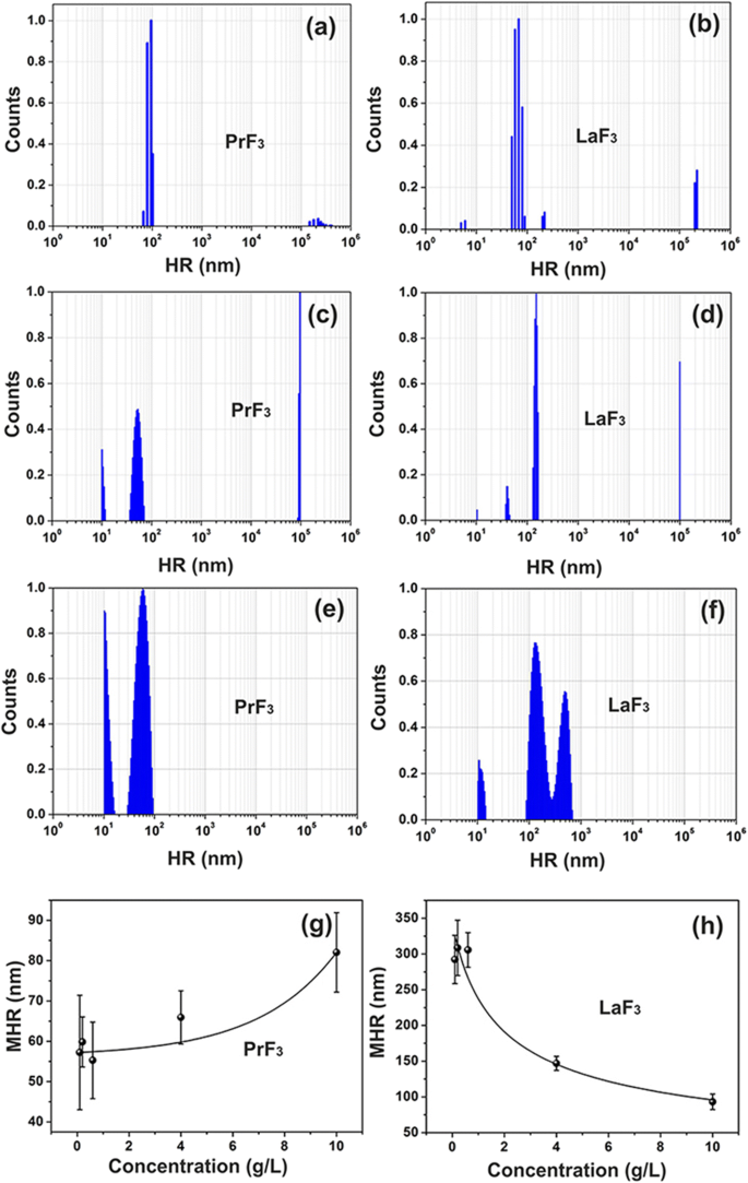
DLS-Größenverteilungsspektren von RE-Suspensionen. a, b PrF3 und LaF3 NP (5 g/L) in Wasser. c, d PrF3 und LaF3 NPs (5 g/L) in DMEM+FBS. e, f PrF3 und LaF3 NPs (0,1 g/l) in DMEM+FBS. g, h Mittlerer hydrodynamischer Radius (MHR) mit Standardabweichung von PrF3 und LaF3 NPs in DMEM+FBS in verschiedenen Konzentrationsstufen
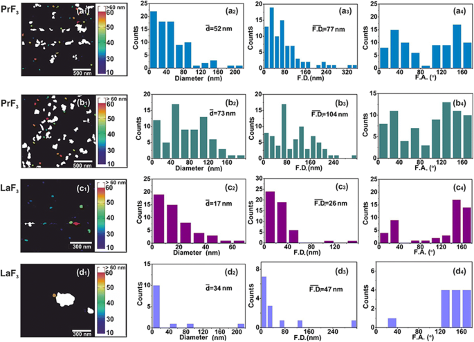
AFM digital (x , y ) Größenhistogramme von RE-NPs. (a1–d1 ) PrF3 (2 × 2 μm 2 ) und LaF3 (1 × 1 μm 2 ) NPs in DMEM+FBS-Suspensionen. (a2–d2 ) (x , y ) Größenhistogramme des mittleren gleichen Kreisflächendurchmessers \( \left(\overline{d}\right) \) von RE-NPs. (a3–d3) (x , y ) Größenhistogramme von Feret-Flächendurchmessern \( \left(\overline{\ F.D.}\right) \) von RE-NPs. (a4–d4 ) Feretwinkel (F.A.) Histogramme relativ zum x -Achse. RE-NPs wurden entlang zweier Hauptrichtungen zwischen ±(44–60°)
. ausgerichtet
TEM digital (x , y ) Größenhistogramme von RE-NPs. (a1, b1 ) TEM-Bilder von RE-NPs. Gelbe Linien zeigten 2D-Grenzen zwischen RE-NPs an. (a2, b2 ) (x , y ) Größenhistogramme des mittleren gleichen Kreisflächendurchmessers \( \left(\overline{d}\right) \) von RE-NPs. (a3, b3 ) (x , y ) Größenhistogramme des Feret-Flächendurchmessers \( \left(\overline{\ F.D.}\right) \) von RE-NPs. (a4, b4 ) Feretwinkel (F.A.) Histogramme relativ zum x -Achse mit Vorzugsrichtungen bei ±(44–60°). (c ) Größenhistogramm des Feret-Durchmessers kleiner und winziger RE-NPs, extrahiert aus AFM- und TEM-Bildern für 4 μm 2 Bereiche
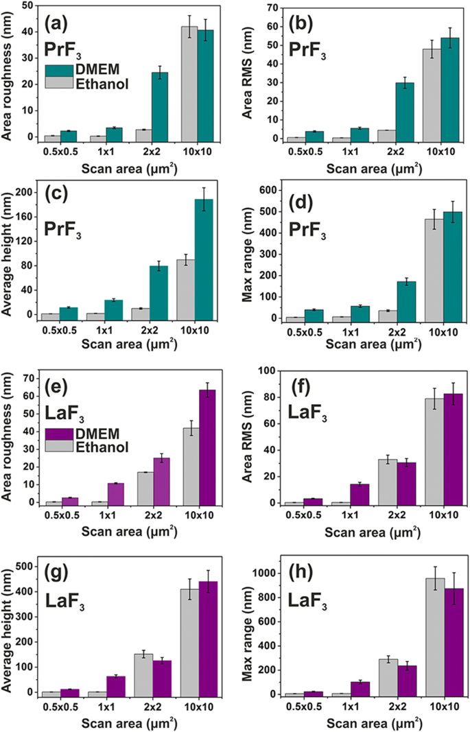
Oberflächenparameterhistogramme (z-Höhe) von PrF3 und LaF3 RE-NPs auf einem Glassubstrat in DMEM+FBS und Ethanol für verschiedene Scanbereiche. a , e Rauheit der Fläche. b , f Bereich RMS. c , g Durchschnittshöhe. d , h Maximal z -Bereich
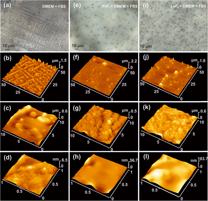
AFM und optische Bilder von getrockneten RE-NPs in DMEM+FBS. a –d Optisch (a ) und AFM-Bilder (b –d ) von DMEM+FBS mit 5 μm selbstorganisierten Strukturen. e –h CCD (e ) und AFM-Bilder (f –h ) von PrF3 NPs in DMEM+FBS-Medien mit 500 nm selbstorganisierten Dendritenstrukturen. ich –l CCD (i ) und AFM-Bilder in verschiedenen Vergrößerungen (j –l ) von LaF3 NPs in DMEM+FBS mit 100 nm selbstorganisierten Dendritenstrukturen
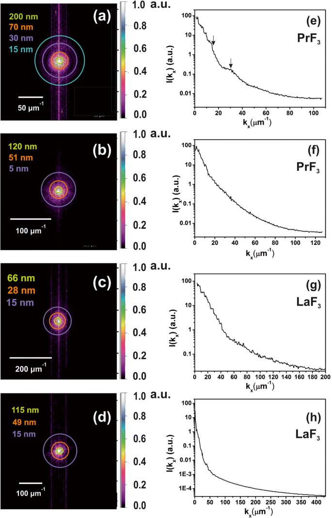
2D-FFT-Spektren von z -Höhenverteilung von getrockneten RE-NPs in DMEM+FBS-Medien, die das Vorhandensein kleiner NPs in den flüssigen Suspensionen belegen. a , b z-Höhenverteilung von PrF3 NPs aus AFM-Bildern, Abb. 2(a1, b1). Kleine z -Höhenmerkmale (~ 5 nm) wurden in (b ). c , d z-Höhenverteilung von LaF3 NPs aus AFM-Bildern, Abb. 2(c1, d1). e , f Leistungsspektren von z -Höhenwellenvektoren von PrF3 NPs entlang des x -Achse. g , h Leistungsspektren von z -Höhenwellenvektoren von LaF3 NPs entlang des x -Achse
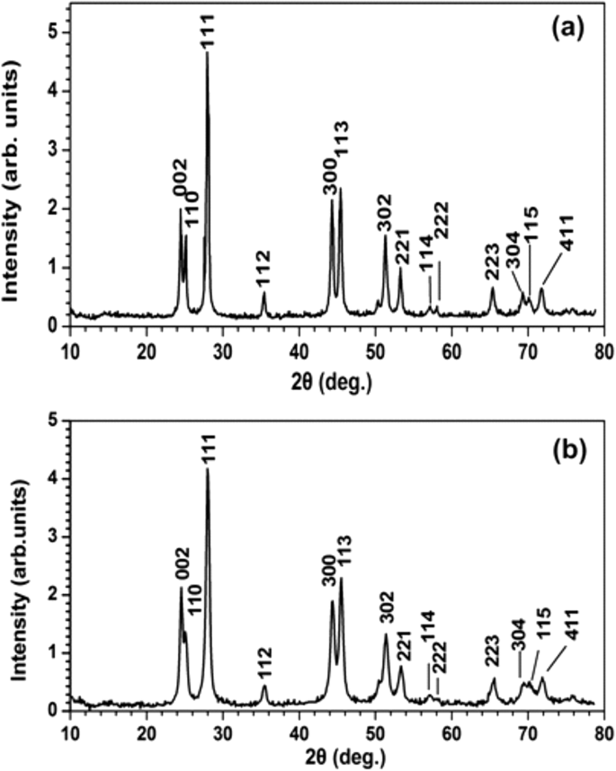
XRD-Spektren von a PrF3 und b LaF3 NPs. Die mittleren Oberflächendurchmesser von PrF3 und LaF3 NPs waren ~ 23 ± 4 bzw. ~ 15 ± 4 nm
DLS
Trübe heterogene Mischungen wurden zunächst durch Zugabe von RE-NPs in Zellkulturmedien gebildet, was die Komplexität der Wechselwirkungen zwischen RE-NPs in flüssigen Suspensionen verdeutlicht. Winzige (< 10 nm), kleine (> 10 und < 20 nm) und große (> 20 nm) Strukturen von RE-NPs wurden für beide PrF3 . identifiziert und LaF3 lösliche Stoffe (Abb. 1a–d).
Die Werte des mittleren hydrodynamischen Radius (MHR) großer RE-NPs (55–83 nm für PrF3 und 99–296 nm für LaF3 ) wurden direkt und umgekehrt proportional zum Konzentrationsniveau der NPs (0,1–10 kg m −3 ) in flüssigem Dulbecco’s modifiziertem Eagle’s mit fetalem Rinderserum (DMEM+FBS), Abb. 1g, h. Auch die MHR des kleinen LaF3 und PrF3 Die NPs blieben bei unterschiedlichen Konzentrationen von RE-NPs konstant, 10,66 ± 0,74 nm bzw. 10,64 ± 0,40 nm. Die MHR von RE-NPs blieb für mindestens 6 Tage unverändert. Nach dem Trocknen der RE-NP-Suspensionen war es unmöglich, das RE-Pulver wieder aufzulösen, da große Agglomerationen, die durch starke Wechselwirkungen stabilisiert wurden, die Ausfällung erzwangen.
AFM- und TEM-Bildgebung von RE-NPs und Oberflächenanalyse
Für eine zuverlässige Größenverteilung und Statistik kleiner RE-NPs in DMEM+FBS bei 0,1 kg m −3 AFM (Scanbereiche 1 × 1 und 2 × 2 μm 2 ) und TEM-Bildgebung wurden ebenfalls angewendet (Abb. 2(a1–d1) und Abb. 3(a1, b1)). Nach der Übertragung der Flüssigkeitstropfen der RE-NPs in DMEM+FBS auf das Glassubstrat wurde eine relativ große Anzahl nicht aggregierter winziger RE-NPs identifiziert [38] sowohl aus der mittleren Größe als auch aus dem mittleren Feret-Durchmesser der NPs ( Abb. 2(a2–d2, a3–d3) und Abb. 3(a2, b2, a3, b3)). Auch die Histogramme der Winkelverteilung der AFM- und TEM-Feret-Durchmesser (für die größere Dimension der NPs) zeigten, dass beide RE-NPs bevorzugt in zwei Richtungen zwischen ± (44–62 o ), relativ zum x -Achse (Abb. 2(a4–d4) und Abb. 3(a4, b4)).
Trotzdem z -Höhenverteilung der NPs liefert keine direkten Informationen über die Gesamtgrößenverteilung der NPs, es ist ein praktisches Vergleichswerkzeug für die erste Schätzung von (x , y ) Größenverteilung, da die z-Höhe und (x , y ) Verteilungen bleiben miteinander verbunden [38].
Die mittleren Oberflächenparameter beider PrF3 und LaF3 in getrockneten Suspensionen für verschiedene AFM-Scanbereiche sind auch in Abb. 4 dargestellt. Die kleinen z -Höhenwerte zeigten ein sehr einheitliches z . an -Höhenverteilung beider RE-NPs für kleine 1 × 1 μm 2 Bereiche scannen. Im Gegensatz dazu ist sowohl für RE-NPs als auch für größere Scanbereiche die z -Höhenverteilung war deutlich breiter. Das niedrige z -Höhenverteilungswerte bei kleinen Scanbereichen spiegeln das Vorhandensein kleiner RE-NPs in den flüssigen Suspensionen wider. Die Oberflächenparameterwerte in DMEM+FBS-Medium waren im Durchschnitt größer als in Ethanol, was einen komplexen reaktiven Zustand zwischen Proteinen und RE-NPs zeigt, in Übereinstimmung mit der facettenreichen Strukturierung von Abb. 5 und den 2D-FFT-Daten (Abb. 6 .). ). Insgesamt LaF3 NPs zeigten eine faszinierende Reaktion in getrockneten Suspensionen und umfangreichere Oberflächenrauheitsparameter als PrF3 NPs.
FFT
In den 2D-FFT-Spektren wurden Farbringe in ausgewählten Radien hinzugefügt (Abb. 6a–d). Die Zyklen repräsentieren unterschiedliche Größenverteilungen der NPs im euklidischen Raum, von einer winzigen Größe gleich einer Pixelgröße (1,9–3,9 nm) bis zu einer beträchtlichen Größe von ~ 2 μm, was die obere Abtastgrenze der AFM-Spitze im z -Achse (Abb. 6e–h). Eine entfaltete der z -Höhenwerte mit dem Radius der AFM-Spitze liefern eine tatsächliche Auflösung im z -Höhenverteilung von ~ 5 nm. Die 2D-FFT-Spektren zeigten eine starke Verteilung der Wellenvektoren in der Nähe des Zentrums aufgrund eines mittleren z -Höhe der RE-NPs von ~ 44 nm. Die FFT-Muster zeigten eine Halo-Struktur, die aufgrund einer polydispersen, breiten, winzigen Struktur, die in den 2D-FFT-Spektren identifiziert wurde, allmählich verwischt wird. Da in den Spektren nur der Halo ohne Beugungsmuster für beide 2D-FFT-Spektren auftrat, fehlten regelmäßige selbstorganisierte Strukturen. Die aus den ringförmigen 2D-FFT-Mustern von PrF3 . erhaltenen charakteristischen Korrelationslängen und LaF3 waren ~ 51, 70 nm bzw. 28, 49 nm, in Übereinstimmung mit den MHR-Werten, die aus den DLS-Spektren extrahiert wurden.
XRD
XRD-Spektroskopie charakterisierte die Kristallstruktur und lieferte ergänzende Informationen über die Größe von PrF3 und LaF3 NPs (Abb. 7). Die scharfen Beugungspeaks, die der hexagonalen Standardphasenstruktur beider RE-NPs entsprechen, zeigen einen hohen kristallinen Zustand der agglomerierenden Phasen. Unter Verwendung der Scherrer-Formel (\(\tau =\frac{0,9\lambda}{\beta\cos\left(\theta\right)}\Big)\) wird der mittlere mittlere flächengleiche Kreisdurchmesser (MEAC) τ von PrF3 und LaF3 NPs wurden auf ~ 23 ± 4 bzw. ~ 15 ± 4 nm geschätzt.
VUV-Spektroskopie
Das VUV-Transmissionsspektrum des hydroskopischen PrF3 NPs-Schicht auf CaF2 . abgeschieden Substrat von 125 nm (~ 10 eV) bis 190 nm (~ 6.5 eV) ist in Abb. 8 dargestellt. Die VUV-Peaks bei 140–170 nm wurden zuvor den Übergängen von Pr 3+ . zugeschrieben dreiwertige Ionen aus dem Boden 4f elektronische Zustandskonfiguration zu den Stark-Komponenten des 4f5d elektronische Konfiguration in YF3 , LaF3 , KY3 F10 und LiLuF4 Einkristallmatrix und sie sind mit einer Wasser-VUV-Absorptionsbande überlagert, was das Vorhandensein von gebundenen Wassermolekülen im PrF3 . offenbart und LaF3 Kristalle.
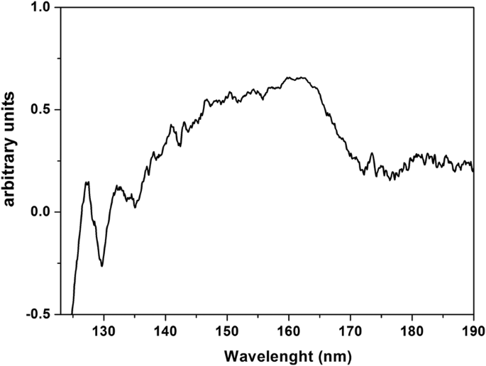
VUV-Transmissionsspektrum von PrF3 NPs in Wassersuspensionen, die auf dem getrockneten CaF2 . abgelagert wurden Substrat. Das Spektrum zeigt Wasseranlagerungen und -einschlüsse in PrF3 . an NPs
Lebensfähigkeitstest
Nach der Größenverteilungsanalyse und Statistik der RE-NPs wurde der Lebensfähigkeitstest der wasserlöslichen Tetrazoliumsalze (WST) verwendet, um die Toxizität von PrF3 . zu überwachen und LaF3 NPs für drei menschliche Krebszelllinien, A549 aus Lungenkrebs, SW837 aus Dickdarmkrebs und MCF7 aus Brustkrebs. Drei verschiedene Konzentrationen von RE-NPs-Suspensionen (0,5, 1 und 5 mM) in DMEM+FBS (A549, SW837) und Roswell Park Memorial Institute Medium mit fetalem Rinderserum (RPMI+FBS) (MCF7) wurden verwendet. Die Zelllinien wurden anfänglich auf 96-Well-Platten platziert und über Nacht zum Anheften belassen. Um innerhalb des linearen Bereichs des Zellwachstums zu sein und eine Sättigung (Abb. 9a) einen Tag später zu vermeiden, frisches Medium mit PrF3 und LaF3 Suspensionen wurden hinzugefügt und Lebensfähigkeitstests wurden 24 und 48 Stunden später nach der Zugabe von RE-NPs oder 48 und 72 Stunden nach dem anfänglichen Moment der Zellplattierung durchgeführt. Für die drei Konzentrationen und die drei Kulturzelllinien wurde jedoch ein Überwuchsunterschied festgestellt, vorausgesetzt, dass das Medium nicht ersetzt wurde und keine zusätzlichen RE-NPs in die Kultur hinzugefügt wurden, Praktiken, die die Anfangsbedingungen des Experiments verändern. Außerdem war es unmöglich, eine Zellkonzentration von weniger als ~ 5 × 10 4 . zu plattieren Zellen pro Well, da die Konfluenz der drei Zelllinien zu gering war, um ein messbares Zellwachstum zu gewährleisten. Der optimale Versuchsaufbau wurde für ~ 5 × 10 4 . eingerichtet Zellen pro Vertiefung.
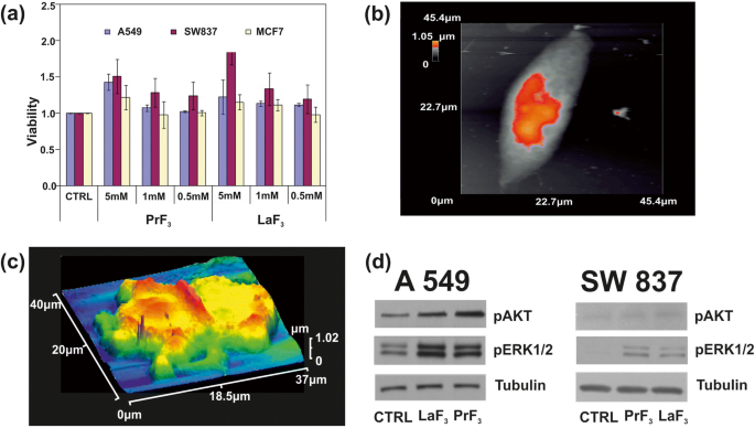
a WST-Viabilitätsassay-Histogramme von drei verschiedenen Krebszelllinien (A549, SW837, MCF7), die mit unterschiedlichen Konzentrationen von PrF3 . behandelt wurden und LaF3 Nanopartikel in biologischen Medien. b AFM-Bild einer einzelnen A549-Krebszelle. c AFM-Bild einer geteilten A549-Krebszelle in RE-NPs in DMEM+FMS. d Wb-Phosphorylierungsanalyse der A549-, SW837-Zellen mit AKT- und ERK-Signalwegen
Bei höheren Konzentrationen (5 mM) wurde für beide RE-Suspensionen ein aufsteigendes Wachstum für alle Zelllinien erhalten (Fig. 9b, c). Unter ihnen war der höchste Wachstumswert für die SW837-Linie (86%, LaF3 .). ). Weniger ausgeprägt, aber immer noch relevant, wurde bei der MCF7-Zelllinie bei 5 mM eine Zellüberwucherung (15%) festgestellt. A t statistische Analyse testen (p und Fisher F Werte) der Lebensfähigkeit von Tumorzellen zeigten, dass das Wachstum der Tumorzellen nach 24 h ungesättigt war; es folgte einem unbekannten physikalischen Gesetz, das die Lebensfähigkeit und Konzentration von RE-NPs verband (Zusatzdatei 1).
Phosphorylierungsassays
Der Phosphorylierungsstatus von zwei Proteinen wurde ebenfalls getestet (Fig. 9d). Unter Verwendung spezifischer Antikörper und Wb-Assays in den Zelllinien A549 und SW837 wuchs in DMEM+FBS mit 5 mM LaF3 und PrF3 NPs für 24 h, hohe Phosphorylierungsaktivität von ERK1/2 und AKT in behandelten Zellen im Vergleich zu Kontrollzellen (CTRL) wurde erhalten.
Diskussion
Die relative Wachstumsrate der Krebszellen stieg bei höheren Konzentrationen beider RE-NPs ( 9a ). Die MHR-Werte von RE-NPs in DMEM+FBS wurden jedoch direkt verfolgt (PrF3 ) und umgekehrt proportional (LaF3 ) auf die Konzentration von RE-NPs von 0,1–10 kg m −3 (Abb. 1g, h). Daher sollten RE-NPs mit einer durchschnittlichen Größe über ~ 55 nm keinen Einfluss auf das Zellwachstum haben und nur winzige NPs können tatsächlich am Tumorwachstum teilnehmen.
Größe und Struktur von RE-NPs
Identifizierung winziger RE-NPs
Aus den experimentellen Daten wurden die mittlere Größe, Verteilung und die statistischen Parameter der RE-NPs extrahiert. Durch Anwendung von t Teststatistik für die „Nullhypothese“ des „mittleren Flächengleichheitskreises“ von NPs in getrocknetem PrF3 und DMEM+FBS-Aufhängungen, die p Wert des Durchmessers von NPs zwischen zwei zufällig ausgewählten AFM-Bildern betrug ~ 0,001 (Zusätzliche Datei 2). Ein Wert des MEAC-Durchmessers (63 nm) wurde mit Vertrauen aus den AFM-Daten extrahiert, und dieser war vergleichbar mit dem MHR-Wert aus den DLS-Daten (Abb. 1g).
Im Gegenteil, der Wert des MEAC-Durchmessers von zufällig ausgewählten LaF3 Proben zeigten einen durchschnittlichen MEAC-Durchmesser von 26 nm mit einem höheren Ablehnungswahrscheinlichkeitswert (p = 0.07), was auf ein divergierendes Verhalten von LaF3 . hinweist in flüssigen Suspensionen. Die Diskrepanz zwischen dem MEAC-Durchmesser und der MHR von DLS (296 nm) (Abb. 1) ist auf die Komplexität der Wechselwirkungen in LaF3 . zurückzuführen wieder Aussetzungen. Tatsächlich für ein 2 × 2 μm 2 Scanbereich der AFM-Spitze, der durchschnittliche z -Höhe war ~ 140 nm, was das Vorhandensein von großformatigem LaF3 . anzeigt NPs, übertragen aus den flüssigen Suspensionen auf das Substrat (Abb. 4). Für die „Null-Hypothese“ von „gleichen MEAC-Durchmesserwerten aus zufällig ausgewählten TEM-Proben“, die p Werte waren auch klein (p = 0,001). Für beide RE-NPs die durchschnittlichen MEAC-Durchmesserwerte, die aus den kombinierten TEM- und XRD-Daten für beide PrF3 . extrahiert wurden und LaF3 angezeigtes hohes p Werte, p = 0,29 bzw. 0,06, so dass keine Korrelation zwischen den TEM- und XRD-Daten möglich ist. Nur TEM, AFM (PrF3 ) und DLS-Daten waren ausreichend zuverlässig, um MEAC-Durchmesser und Kern-Schale-Werte zu extrahieren (Zusatzdatei 2).
Außerdem zeigte eine nicht isotrope Winkelverteilung der Feret-Durchmesser, dass sowohl PrF3 und LaF3 Strukturen waren hochpolarisierte Dielektrika, da die anisotrope Winkelverteilung ein Hinweis auf starke elektrische polare Wechselwirkungen zwischen Nanokristallen ist. Ein vielfältig polarisierter Zustand von LaF3 war verantwortlich für das Herunterskalieren der relativen Effizienz des agglomerierenden Zustands in Suspensionen und eine Hochskalierung der Oberflächenrauheitsparameter in getrockneten Proben.
Eine Software-Partikelanalyse von zufälligen AFM-Bildern für 5 μL und eine Konzentration von 0,1 kg m −3 identifizierte eine Anzahl von ~ 22 und ~ 11 RE-NPs mit einer Größe kleiner als 15 nm und 10 nm (p = 0,001) bzw. eine Anzahl von ~ 60 RE-NPs aus TEM-Bildern (p = 0,001) in einer Fläche von ~ 4 μm 2 , was somit das Vorhandensein von RE-NPs winziger Größe in den Suspensionen bestätigt (Abb. 3(c), zusätzliche Datei 2), die mit DLS nicht erkannt wurden.
Struktur und Geometrie von RE-NPs
Die Größenverteilung der RE-NPs ist in Ethanol- und DMEM+FBS-Suspensionen unterschiedlich (Abb. 4). Die Diversität beruht auf unterschiedlichen molekularen Wechselwirkungen zwischen den adsorbierten Proteinen, Kohlenhydraten, Elektrolyten und der Oberfläche von RE-NPs, die zur Bildung hochkomplexer organischer Hüllen (Corona) führen, die die spezifischen Wechselwirkungen von RE-NPs mit Zellen in . modulieren DMEM+FBS-Medium.
Das Zusammenspiel zwischen in hygroskopischen RE-NPs eingeschlossenen Wassermolekülen und DMEM+FBS war auch für die Kern-Schale-Bildung entscheidend. Es hatte auch eine tiefgreifende Wirkung auf Protein- und Konformationsänderungen in den Zwischeninteraktionen während der Anfangsphase der Herstellung. Da das Verhältnis von Oberfläche zu Masse von NPs in den Suspensionen hohe Werte entwickelte, waren die effektive Stabilität und die physikalisch-chemischen, mechanischen und Fließeigenschaften von RE-NPs, einschließlich der Fähigkeit, Proteine zu absorbieren, äußerst unterschiedlich [39,40,41] .
Eine vergleichende Größenverteilung von RE-NPs in Flüssigkeit (DLS) und verfestigten Suspensionen mittels AFM und TEM zeigte, dass RE-NPs in organischen Formen eingekapselt waren, die dielektrische Kern-Schale-Strukturen bildeten, wobei eine proteinhaltige Hülle den RE-Kern umgibt. Die AFM-Aufnahmen von verfestigten RE-NPs in DMEM+FBS-Suspensionen, die auf Glassubstraten abgeschieden wurden, weisen ebenfalls auf die Bildung von facettenreichen RE-NPs und Proteinkoronakomplexen hin (Abb. 5). Während getrocknete Medien ein regelmäßiges selbstorganisiertes Muster von Kristallstrukturen bildeten (Abb. 5a–d), zeigten getrocknete RE-NP-Suspensionen eine amorphe Schichtstruktur mit mehreren schwarzen Flecken, die sogar mit der Digitalkamera des AFM sichtbar waren (Abb. 5e–l). . Bei höherer optischer Vergrößerung wurden für beide RE-NPs in DMEM+FBS auch diskrete Ansammlungen von Kugelformen, die kleiner als die im Medium allein waren, zusammen mit dendritenartigen Strukturen nachgewiesen, die beide die Komplexität der Wechselwirkungen zeigen, in Übereinstimmung mit den Ergebnisse der Oberflächenparameter (Abb. 4). Selbst bei höchster AFM-Auflösung (1 × 1 μm 2 Bereich), der letzten Spur von Abb. 5, wurden in getrockneten Strukturen für beide RE-NPs keine isolierten RE-NP-Aggregationen innerhalb der Auflösungsgrenze von ~5 nm identifiziert. Die schwarzen sphärischen Myzelien mit einer Länge von 1–2 μm, die in den optischen Bildern gezeigt werden, waren große agglomerierende Formationen von Kern-Schale-RE-NPs. Die Komplexität der Reaktionen zwischen den RE-NPs und DMEM+FBS wurde durch die Transformation der selbstorganisierten langgestreckten Langzeitstrukturen in reinem DMEM+FBS in Dendritenstrukturen visualisiert.
Die Ergebnisse weisen auf das Bild einer einzelnen RE-NP-Kernstruktur hin, die in eine Proteinhülle eingekapselt ist. Diese Strukturen waren nicht nachweisbar, da sie von organischem Material und Elektrolyten umgeben waren, die beide mit RE-NPs kreuzreagierten. Das VUV-Spektrum von PrF3 shows some spectral peaks between 140 and 170 nm (Fig. 8). The ionic transitions are overlapped by a VUV water absorption band extended from 145 to 180 nm with a maximum at 168 nm. Only the spectral signatures of the 4f6s electronic configuration with maxima at 132 and 127 nm were present in the spectrum. However, these bands could evince the presence of water in the high hygroscopic PrF3 suspensions. Water has a rich, structured absorption band in the VUV spectral range centred at 122 nm, revealing the presence of water molecules in the core-shell NPs.
Activation of Mechanosensors
Activation of Integrins by External Forces
The activation of oncogenic pathways by RE-NPs [24], besides the 3D structural nature of TSRs, is based on some Natural Evolution principles for sustaining the viability of cells. First, upon binding a specific external ligand in a LABS, conformational changes along the entire TSR spectrum underline a series of cascading pathways, triggering tumour cell growth (Fig. 9c, d). The transmission of signals advances through the plasma membrane via various protein chains. Signal transduction was via conformational transformations of integrins responding to a high affinity external force (Fig. 10a, b).
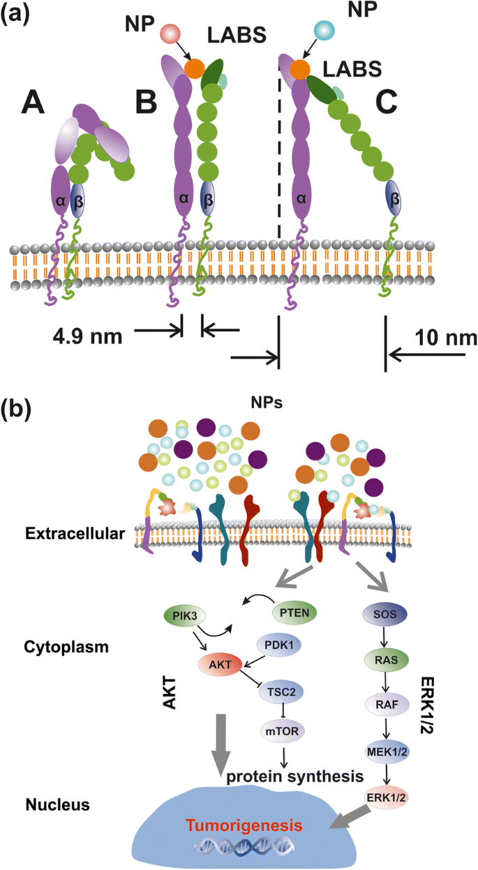
Simplified layout of integrin activation by NPs and signal transaction pathways. a Structure and conformational geometries of integrins at a low (A), medium (B) and high-affinity strengths (C). b AKT and ERK1/2 signal transaction pathways activated by RE-NPs via external integrin stimulation
Because of “life sustainability” and “survival laws” that prevents cancer cell growth by random “noise”, it is required that the strength of the external force should be within a bounded range of values and also the external strength stimulus should apply for a long period on a large number of mechanosensors in a cancer cell. The external strength that stimulates cancer must be slightly larger than the strength of the interatomic molecular forces under normal conditions. For a thermal energy of a ligand at room temperature (kT = 0.025 eV, T = 298 K), and for a regular thermal stress of molecular bonds of ~ 0.05 nm, the mean thermal force acting on the LABS stays for 1.2 × 10 −12 N. In principle, a force above ~ 10 × 10 −12 N acting coherently on the whole set of mechanosensors on a cell should activate signal transduction in tumour cells. Consequently, ignoring any thermal and mechanical stressing in the ECM normal conditions, integrin activation via electrical polar interactions between LABS and NPs has the potency to start signal transduction in cancer cells and to initiate tumorigenesis.
Integrin Structure and Geometry
An integrin receptor in the upright conformation state extends ∼ 20 nm upwards from the cell membrane [42] (Fig. 10a). For no contacts between the two α- and β-subunits, other than those in the headpiece near the ligand-binding pocket, the α- and β-subunits are well separated with their cytoplasmic tails extended out up to ∼ 8 nm [42]. A conic projection geometry (20 nm slant height, 5–10 nm diameter of its circular base), bounded by the α- and β-subunits, defines a projected area on the surface of cell’s membrane between ~ 19 and ~ 80 nm 2 , for a typical mean radius of a tumour cell R c ≈ 5 μm (equivalent surface area of a spherical cell \( {S}_c=4\pi {R}_c^2=3.14\ \mathrm{x}\ {10}^8\ {\mathrm{nm}}^2 \)). By dividing the area S c of a spherical tumour cell surface with the projected area of an integrin on a cell surface, an upper limit of the number of integrin receptors for these projected areas was n int = 1.6 x 10 7 and 3.9 × 10 6 bzw. These numbers are compared with the mean number of integrins on a cell \( {\overline{N}}_{int}\approx 2\ \mathrm{x}\ {10}^5 \) and for an average interspacing of 45 nm between adjacent integrin receptors [43]. Nevertheless, \( {\overline{N}}_{int} \) might be larger because of an uneven surface structure, different separating distances between integrins and variable size of tumour cells (Fig. 9c), but the number of integrins on a cell membrane stand between n int and \( {\overline{N}}_{int} \).
Interaction of Mechanosensors with RE-NPs
ERK ½ and AKT Activation
The TEM images and the elemental mapping of F, La and Pr showed that RE-NPs were unable to penetrate inside the cell. They gathered around the A549 cell membrane (Fig. 11), confirming that an external force can stimulate cell growth because of TSRs activation [44]. The Pr atoms were distributed around the boundaries of the cell’s membrane. The small numbers of F, La and Pr identifications inside the cell were not associated with endocytosis of RE-NPs, but they were images of RE-NPs from the projections of the two cells hemispheres on cell’s equatorial cycle.
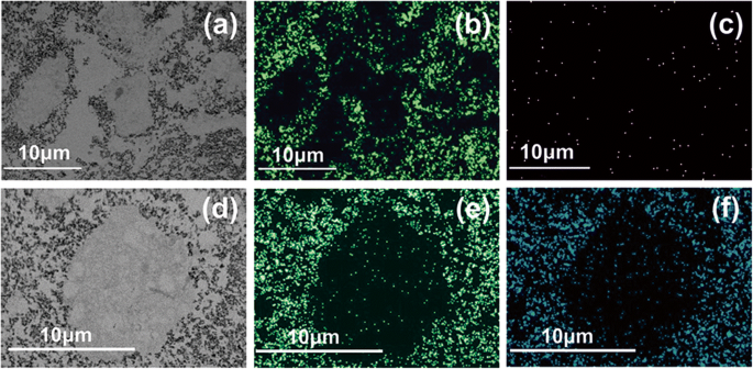
TEM images and elemental analysis of RE-NPs at the surface boundaries of A549 cells. a TEM image of small size LaF3 NPs surrounding the A549 cells. b Elemental analysis of F atoms in RE-NPs distributed around the cell. c Elemental analysis of La atoms. The low concentration of La atoms was associated with a rather small scattering efficiency of the X-rays. d –f The same as for (a –c ) for PrF3 RE-NPs
It was also evident that both RE-NPs were able to enhance AKT phosphorylation, especially in A549 cells (Fig. 9d), where the steady-state level of AKT pathway activity was higher for the SW837 cell line. The phosphorylation level for the MCF7 cell line was below the detection limit, in agreement with the relatively low levels of growth. High phosphorylation levels of ERK1/2 [36] and AKT were detected in A549 and SW837 cell lines. Cell growth was started once NPs with a proper size interact with the mechanosensors of the cells to provide the correct force for initiating cell growth [45, 46]. ERK and AKT pathways were frequently active in several cancer cell types via extracellular springing, as they were stimulated by the TSRs, upon a selective binding with various mitogenic ligands, or via the activation of the mechanosensory group. The interaction was responsible for a continuous intracellular stimulation that, according to the cell’s phenotype, driven the cancer cells to uncontrolled and endless growth. Viability tests were also run for 48 and 72 h, but the growth of all cell lines was saturated at 48 and 72 h after the initial moment of Cell plating.
Interaction of Cells with Ions
Likewise, as fluoride anions are the most reactive electronegative elements and, the mean radii extension of the unscreened 4f electronic configuration of La and Pr trivalent ions are relatively large, high electric surface charges could be developed via electric dipole interactions [47].
One crucial question stands whether a single ion binding on a specific site can activate tumour cell growth. Because the projected area of the 4f electronic configuration of a single RE ion is S 4f = 0.040 and 0.043 nm 2 (for an approximated spherical geometry of the 4f electronic configuration and a 4f mean orbital radii ~ r 4f =0.113 and 0.117 nm for Pr and La ions, respectively), a typical upper limit number of single RE ions, or other equivalent size ions, over the whole area of the cell membrane was ~ Sc / S 4f = N 4f ~7.9 × 10 9 RE ions; a number which is at least two orders of magnitude above the upper limit of the mean number of integrins on a tumour cell. As the relative overgrowth of cells was ascending with rising concentration (Fig. 9a), it is unlikely that tumour cell growth is triggered by a specific binding of single trivalent RE ions [48] on the ligand sites [49,50,51]. Indeed, the large number of RE ions should have saturated the cell’s growth and thus the viability of cells should have remain independent from the concentration of the RE ions.
Interaction of Integrins with RE-NPs
Within the requisite force range of few pN, and for efficient activation of integrins from NPs, the interaction between NPs and LABS should activate a large fraction of integrins of the cell for a long time. In the most extreme favoured case for cell growth, the number of NPs had to remain equal with the number of integrins on the cell’s surface, and the interactive force between LABS and NPs has to be attractive for obtaining a constant (long-term) action. A thin spherical shell of spherical NPs surrounding a tumour cell occupied a volume\( {V}_{sc}\approx 4\uppi {R}_c^2x \), where R c = 5 μm is the cell radius and x ≈ 20 nm is half the separating distance between adjacent integrin receptors and V sc ≈ 6.3 x 10 9 nm 3 . For justifying the requirement that each integrin receptor interacts only with one NP, a first estimation of the size of NPs to meet the above requirements for the whole set of integrins on a cell is obtained by dividing the volume of the spherical shell V sc with the number of integrins. A simple calculation for a cell radius 5 μm shows that the limits of radii of NPs activating the whole set of integrins within the spherical shell volume V sc ≈ 6.3 x 10 9 nm 3 covering the cell is obtained by divided the volume V sc with the number of integrins \( {\overline{N}}_{int}\approx 2\ \mathrm{x}\ {10}^5 \) and n int ≈ 1.6 x 10 7 . The volume of the spherical NPs stands for 3.15 × 10 4 and 3.93 × 10 2 nm 3 bzw. Therefore, the radii of the NPs interacting with an integrin lay between ~ 20 and 5 nm. Allowing for one order of magnitude variations in the number of integrins \( {\overline{N}}_{int} \), the radii of the NPs interacting with integrins is between ~ 27 and ~ 3 nm respectively.
By also applying similar simple calculations and within the experimental limits of concentration levels of RE-NPs (0.1–10 kg m −3 ), the maximum numbers of PrF3 with MHR 55–83 nm and LaF3 with MHR 296–100 nm NPs (Fig. 1g, h) covering the surface of a tumour cell V sc stood for 4.1 × 10 4 –2.1 × 10 4 and 17.1 × 10 2 –1.5 × 10 4 NPs. These values are placed well below the number of integrins on the cell surface. For rising concentrations of PrF3 and LaF3 from 0.1 and 10 kg m −3 , the number of PrF3 and LaF3 NPs in the suspensions must go up for either descending or ascending size of NPs. As viabilities of cancer cells are raised at higher concentration levels, it is unlikely that 55–296 nm sized RE-NPs are responsible for cancer cell mitosis under the current experimental configuration.
Also, from the DLS data, the size of both RE-NPs between 10 and 20 nm remained constant (10.6 nm) at different RE concentrations. The number of RE-NPs with this size covering the cell surface is between 3.7 × 10 5 and 1.5 × 10 6 . This number is comparable with the mean number of integrins \( {\overline{N}}_{int}\approx 2\ \mathrm{x}\ {10}^5 \) on a cell surface. Therefore, only small size RE-NPs have the potency to stimulate cancer cell growth by stimulating all the integrins on a cell surface, in agreement with the experimental observations (Figs. 1g, h and 9a).
The number of tiny sizes RE-NPs with MEAC diameter (TEM) from 2 to 10 and 10 to 15 nm on the cell surface (S c = 314 μm 2 ) stands for 1.3 × 10 4 and 1.8 × 10 4 RE-NPs, respectively. Those values stayed one order of magnitude below \( {\overline{N}}_{int}\approx 2\ \mathrm{x}\ {10}^5 \) and therefore tiny size RE-NPs had also the potency to justify the experimental results of rising viability values with concentration (Fig. 9a). Also, the rough surface of tumour cell (Fig. 9c) is able to form cavities, where small size RE-NPs are trapped, triggering thus cell’s mechanosensors. Most important, only tiny size RE-NPs have the potency to activate integrin receptors via electrical dipole interactions (vide infra).
Interaction of EGFR with RE-NPs
An upper limit of small size NPs capable of stimulating cell’s overgrowth via the EGFR was set previously to 14 nm [52], but a realistic size of NPs stimulating the EGFR should be < 5 nm [53] (Fig. 12). The area number density of EGFR on the surface of tumour cells stands for ~ 1.4 × 10 −4 nm −2 and the total number of EGFR on the surface S c of cells remains between ~ 4.2 x 10 4 and 10 5 [54,55,56]. RE-NPs with 5–10 nm size stayed for a number of 34 NPs (Fig. 3). Extrapolating this number to the surface of a cell S c , the total number of RE-NPs remained at ~ 10 4 NPs, a number which matches the number of EGFR receptors on a A549 cell. Therefore, the EGFR have the potency to be activated synergistically also by a number of tiny size RE-NPs.
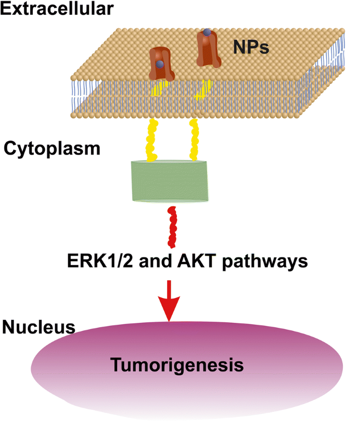
AKT and ERK1/2 signal transduction pathways activated by RE-NPs via EGFR stimulation. EGFR is activated only by tiny size ~ 5 nm NPs
Electric Dipole Interaction Between RE-NPs and LABS
The above experimental results are supported by the hypothesis of cancer cell growth from LABS stimulation by tiny size core-shell RE-NPs via electrical dipole interactions, Appendix.
Indeed, the mean electrical dipole force \( \left\langle {\overrightarrow{F}}_{V_2}\right\rangle \)acting on LABS from a core-shell RE-NP includes two terms (Fig. 13d and Appendix, Eq. A22). The first radial term is inversely proportional to the forth power of separating distance r 1 between the RE-NPs and LABS and is also proportional to the size of NP. The second polar term is inversely proportional to both the separating distance r 1 and the square power of the size of NP,
$$ \left\langle {\overrightarrow{F}}_{V_2}\right\rangle =-\frac{G_1{N}_2{N}_1\ d{e}^2}{4{\varepsilon}_0\ {r}_1\ }\theta \left(\ 3G\frac{b}{r_1^3}{\widehat{r}}_1+\frac{\theta }{2{b}^2}{\widehat{\theta}}_1\right)\kern0.75em (1) $$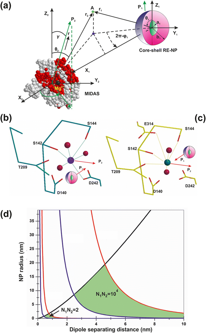
a Electrical dipole interaction between one core-shell RE-NP and one LABS. b , c RE core-shell NP near a MIDAS (b ) and ADMIDAS (c ) adhesion sites. d Locus area (green) of the size of RE-NPs and separating distance between a LABS and a core-shell RE-NP for two electrical charging states
In Gl. 1, G and G 1 are the geometrical factors of NPs, describing either core-shell or core spherical structures, Appendix, Eqs. A6 and A14; N 1 , N 2 are the numbers of surface electrons on the a RE-NPs and LABS surfaces; d and b are the effective characteristic spatial extension of atomic orbitals of LABS, ~ 0.1 nm, and the radius of RE-NP; e and ε 0 are the electron charge and the vacuum permittivity and \( \theta =\frac{d}{r_1}<0.01\ rad \). Because the core of the RE-NPs is a crystalline semiconductive material, an inherent large number of surface and volume defective sites were accountable for a high density of pseudo-electron energy levels that allowed the electrons to move freely within the core volume [46]. Consequently, a core-shell structure had the potency to be highly polarised. Therefore, LABS can be activated efficiently by core-shell RE-NPs via electrical dipole interactions at close separating distances. The high polarised efficiency of the core nucleus was confirmed experimentally via the selective orientation of NPs along two distinct directions (Fig. 2(a4–d4) and Fig. 3(a4, b4)).
The polar interaction force is also proportional to the geometrical factor G 1 , Appendix, Eq. A14. Typical values of dielectric constants of the culture media, shell configuration and RE core components stand for ε 1 = 78, ε 2 = 10 and ε 3 = 15. When the ratio of core-shell to core radii b/a sets within 1 and 50, the geometrical factors G , G 1 retain almost constant values (G = 0.2, G 1 = 0.01) and they are self-same for both a spherical core (b/a = 1) and a spherical core-shell. Any permanent or induced polarisation of an open or closed a-I-MIDAS domain forming the LABS domain has its origin on six coordinated water oxygen atomic orbitals with Mn 2+ or Mg 2+ ions, arranged in a spherical geometric configuration [7] (Fig. 12a–c).
As the electrical dipole force in Eq. 1 stands for the vector sum of a radial (first term) and a polar component (second term), the last term prevails over the first one provided that
$$ {r}_1>\sqrt[3]{6G}b\sim b\kern0.75em (2) $$In this case, a LABS is activated from the polar force component for all (b/a) ratios and, most important this term is inversely proportional to the second power of the size of NPs, in agreement with the experimental results that only tiny or small size LaF3 NPs activated cancer cell proliferation.
The prevailed polar force term for different r 1 and b values and for different Ν 1 , Ν 2 charging states activating the LABS/MIDAS stay within the limits [57,58,59,60].
$$ {10}^{-12}N<\frac{G_1{N}_2{N}_1\ d{e}^2}{8{\varepsilon}_0\ {r}_1{b}^2\ }{\theta}^2<{10}^{-9}N\kern1em (3) $$Inequality 3 relates the size b of the RE core-shell NPs, the separating distance r 1 and the number of the bound or free electrons Ν 2 , Ν 1 on the surface of the two dipoles. The locus of points (r 1 , b ) satisfying the inequality 3 for different surface charge states Ν 1 , Ν 2 is bounded by the black, red and blue lines (Fig. 13c). As there was no specific assumptions for the type of RE-NP, results can be equally applied for any type of polarised NPs.
When the algebraic product of the number of the surface electrons N 1 and N 2 (bound or free) on the LABS and the RE-NP, respectively, was N 1 N 2 = 2, the locus of RE-NPs size and separating distance for integrin activation was < 1 nm. At higher charging states, N 1 N 2 = 10 4 , the locus area spans a wider RE-NPs size and separating distance area set of values, from 0.5 nm–19 nm to 2.5–15 nm, respectively.
From the above analysis, it is found that only tiny or small size NPs can activate LABS at a certain separating distance r 1 and the electrical dipole interaction strength decays inversely proportional to the second power of the size of NPs. From Fig. 13c and for a charging state with N 1 N 2 = 5 x 10 4 , the size of NPs capable to activate LABS is bounded by the limits
$$ 2.5\ \mathrm{nm}Conclusions
Cancer is a complex disease. Tumours are highly heterogeneous, and cell growth, among other factors, depends on dynamical interactions between cells and the continually changing extracellular matrix. Besides random genomic mutations, signal transductions in cells, activating cell growth can be triggered by mechanical, thermodynamic and electrical polar interactions between the microenvironment of the extracellular cell matrix and the membrane’s mechanosensors. Here, we demonstrated that tumour cell proliferation in three different human cancer cell lines (A549, SW837, MCF7) had the potency to be activated by a synchronised and synergetic activation of EGFR or via electrical dipole interactions between tiny size RE-NPs and the LABS of integrins on a cell.
Because the prerequisite force for integrin activation should stand between 10 −12 and 10 −9 N, the size of the active RE-NPs causing cell growth should be within certain limits. Cancer activation is specified by both the electrical surface charges on the LABS and the NPs and by their separating distance. This electric dipole activating force follows an inversely proportional square power law of the radius of NPs, evidencing that only tiny or small size RE-NPs have the potency to stimulate cancer cell growth via electrical dipole interactions, in agreement with the experimental results.
Methods
Synthesis of RE-NPs
PrF3 NPs were synthesised via co-precipitation. Briefly, 4 g of Pr2 O3 were added to 110 mL of 10% nitric acid in a polypropylene glass beaker together with 3 g of NaF under stirring. The mixture was heated to 50 °С and stirred for 45 min until a clear light-green solution appeared. Then it was filtered. The pH of the mixture adjusted to 4 by adding 25% of ammonium hydrate. Next, the mixture was stirred again for 20 min. Finally, the precipitated NPs washed with distilled water by centrifugation.
LaF3 NPs were also synthesised by applying the same protocol in a mixture of La2 O3 (4 g) and NaF (3 g). From both preparations, an aliquot of the suspensions containing NPs was air-dried for structural analysis and the remaining part kept as water suspension for the biological studies.
The suspensions of NPs were prepared in complete DMEM+FBS cell culture medium by adding water suspended NPs directly to the medium to a final concentration of 5 mM. Then, starting from the 5 mM stock solution, some subsequent dilutions using DMEM as a solvent were prepared to a final NPs concentration of 1 mM and 0.5 mM, respectively.
Size Distribution of RE-NPs
XRD
The crystal structure and the size of PrF3 and LaF3 NPs were characterised by XRD spectroscopy, with an X-ray diffractometer (Shimadzu XRD-7000S) in the 2θ range from 10° to 80° using the graphite monochromatised Cu-Ka radiation (1.5406 Å). The weighted average of τ for all peaks was used in the statistics. Weighting, besides β, took into account the relative intensity of every peak of the XRD spectra. The corresponding errors incorporate the reading error (0.3 mrad) and the standard error of the mean (se = σ / √ Ν ).
DLS
The size distribution and the MHR of RE-NPs in water and DMEM+FBS suspension were determined for comparison by DLS at 632.8 nm and right angles at 37 °C with a multi-angle dynamic and static light scattering instrument (PHOTOCOR-FC). The values of the MHR (Stokes radius) and the size distribution of NPs were calculated from the autocorrelation spectra and the Stokes-Einstein relation with the DynaLS software. Because the intensity of scattered light in pure DMEM+FBS was 20 times lower than with RE-NPs additives, the level of aggregating proteins in pure DMEM+FBS was negligible compared with mixed suspensions of RE-NPs in DMEM+FBS medium. MHR and RE-NPs size distribution and size errors were obtained by fitting and processing the data from the DLS instrument with the DynaLS software that allows the MHR to be calculated in different spectral domains of the main size distributions, from 10–10 2 to 10 2 –10 3 nm, Additional file 2.
AFM
Because size distribution below 15 nm was close to the low limit range of DLS, AFM was also applied to evaluate small size distribution. At low concentration of RE-NPs in liquid suspensions and slow drying rates of droplets on glass substrates, the deposits reflected the size distribution in the liquid suspensions [37]. Following the dispersion of RE-NPs in ethanol or DMEM+FBS, a drop of suspension was placed on a clean glass substrate using a micropipette, and then it was dried in air at room temperature for AFM imaging and analysis (diInnova, Bruker). AFM was performed in the tapping mode, in ambient conditions with a phosphorus-(n)-doped silicon cantilever (Bruker, RTESPA-CP), having a nominal spring constant of 40 nN/nm and operating at a resonance frequency of 300 kHz. Surface areas of various sizes (0.5 × 0.5–50 × 50 μm 2 ) were imaged with high spatial resolution (512 px × 512 px) at a scanning rate of 0.2 Hz to identify domains with different size distributions via “scan area filtering” [37]. From the morphological analysis by the SPM LabAnalysis V7 software, the particle’s size distribution, shape and aggregation stage were determined.
The size of NPs for different scanning areas was also noticeable by the particle analysis chromatic bar (Fiji integrated ROI colour coder based on MEAC diameter) (Fig. 2(a1–d1)). The AFM image was transformed into a binary image using an appropriate z -height threshold. Every pixel of the processed image contained information not only for the z -height in the pixel area but also for the presence of particles in the pixel area. The x -histograms of MEAC and Ferret diameter (Fig. 2(a2–d2, a3–d3)) were extracted by using the “Image J 1.51n Fiji distribution software”, with the correct z -height threshold values. The size resolution per pixel was 3.9 and 1.9 nm for PrF3 and LaF3 respectively.
The particle identification, the noise extraction and the particle area data were processed by the “Particle Analyser function” of Fiji software (Fig. 2(a1–d1)). The particle diameter histograms were also analysed. Both the equal area circle diameter (Fig. 2(a2–d2)) and Feret diameter or “calliper diameter” (maximum diameter of a particle among all directions) (Fig. 2(a3–d3)), whose direction was the Feret angle (Fig. 2(a4–d4)), were analysed. The mean equal area circle diameter and the mean Feret diameter were calculated taking into account all particles identified. The associated errors incorporated the actual pixel size in every AFM image and the standard error of the mean (se = σ / √ Ν ).
A t test was performed for every set of AFM images based in the “null hypothesis” that the mean particle diameter was the same for all the AFM images between randomly selected figures (Fig. 2(a1–b1, c1, d1)). The p value (probability that the null hypothesis based on t distribution is not valid) is shown in Additional file 2.
TEM
The same technique was followed for calculating the above parameters in TEM imaging (Fig. 3(a1–b4)). Atomic resolution TEM (Hitachi HT7700 Exalens) imaged either extracellular or intracellular RE-NPs attachment on the A549 cells fixed in glutaraldehyde. Elemental analysis of F, La and Pr were also carried out (Oxford Instruments X-Max 80T).
2D-FFT
Additional information on the NPs size distribution in the (x , y ) plane was also extracted from the 2-D Fourier transform of AFM images of NPs using the relation
$$ I\left({k}_x,{k}_y\ \right)=\iint f\left(x,y\right)\exp \left(i{k}_xx\right)\exp \left(i{k}_yy\right) dxdy $$where f (x , y ) is a size function at a point (x, y ), k x , k y are the associated wavevectors in the inverse Eukledian space at the same point and I (k x , k y ) is the “spectral density” of the function f (x , y ) at the point k x , k y . For most applications, f (x , y ) is the z -height of the NPs at the point (x, y ) and z = f (x , y ).
For a set of discrete data, such as the digitised AFM images, the 2D-FFT was used instead of 2D Fourier transform in the continuous space. For a m × n X-matrix (pixels of an AFM image), the 2D-FFT transform takes the form
$$ \kern1em {Y}_{p+1,q+1}=\sum \limits_{j=0}^{m-1}\sum \limits_{k=0}^{n-1}{\omega}_m^{jp}{\omega}_n^{kq}{X}_{j+1,k+1\kern1.25em } $$where \( {\omega}_m^{jp}={e}^{2 pi/m},{\omega}_n^{kq}={e}^{2 pi/n} \) are the associated frequencies. Then, an appropriate shift along the y -axis was performed and the integers m, n, p, q, k were translated into lengths and inverse lengths respectively by a multiplication with the pixel’s size of the image.
Water Trapping in RE-NPs
VUV Spectroscopy
To appraise the state of water in RE-NP’s complexes during the initial stage of suspension preparation, the adsorption of water molecules on the surface of the hygroscopic PrF3 NPs was identified with a laboratory-made VUV (110–180 nm) absorption spectrometer. It consists of a hydrogen lamp operating in a longitudinal stabilised discharge mode at 10 kV, a stainless steel vacuum chamber and a VUV monochromator (Acton VM502), equipped with a solar blind photomultiplier (Thorn EMI 9412 CsTe) and a laboratory-made data collection system. Thin layers of PrF3 NPs suspensions in water were prepared and dried on 1-mm-thick VUV-grade CaF2 substrates by applying the “drop-casting method”. Then, the CaF2 substrates were placed in the optical path between the hydrogen lamp and the VUV monochromator in a vacuum. The stainless steel 316 vacuum chamber was evacuated initially to 10 − 7 mbar using two turbomolecular pumps at a differential pumping configuration (Edwards EXT 100/200, pumping speed 150 ls −1 ). However, a high outgassing rate of PrF3 sets an upper limit to the background pressure in the vacuum chamber ~ 8.5 × 10 −5 mbar. The relatively low background pressure of both compounds irreversibly damages the VUV optics and the turbomolecular pump after few hours of operation and therefore it sets certain experimental constraints, preventing an equivalent registration of LaF3 spectrum because of high outgassing rates and a low background operating pressure (< 10 −4 mbar). The experimental data (light transmitted through the sample film on CaF2 window) were fitted to a logarithmic response for calculating the transmittance.
Cell Culture and Growth Assay
Cell Growth
The A549 and SW837 cell lines were maintained in DMEM+FBS, whereas the MCF7 lines were in RPMI+FBS. Both media supplemented with 10% fetal bovine serum (FBS), 1 × penicillin, 1 × streptomycin and 2 mM l-glutamine. Cells were incubated at 37 °C, 5% CO2 in a humidified atmosphere.
The WST viability test was used to monitor the intrinsic toxicity of PrF3 and LaF3 NPs for three human cancer cell lines, A549, SW837 and MCF7. For the viability assay, three different concentrations of RE solubles (0.5, 1 and 5 mM) in DMEM+FBS (A549, SW837) and RPMI+FBS (MCF7) were used. The initial number of cells seeded in the 96-well plates was ~ 5 × 10 4 cells/well. This amount of cells was plated 24 h prior to the RE-NPs treatment of cells in order to allow enough time for the cells to attach properly to the plate (wells) and to attain the optimum growing conditions. Subsequently, the viability test was performed 24 h after RE-NPs addition, or 48 h after the initial cell cultures were placed in the wells. As we did not observe any cell reduction, but on the contrary cell-overgrowth, especially with the SW620 cell line at 5 mM, the cell confluence quickly reached 80–90% of its initial value after 24 h of the addition of RE-NPs or 48 h from the initial plating.
Five microliters of WST solution was added to each well and the plate was incubated for 1 h during the growth state. The absorbance at 450 nm of each well was measured using a microplate reader (Biorad, x Mark). Each experimental point for each cell line and each RE suspension was extracted from two samples and triplicated every 2 days (total of 108 samples).
F test was used for every set of cell viability measurements. Here, the “null hypothesis” was that the relative to the CTRL “mean viability value was the same at different concentrations within the same cell line”. With this null hypothesis, an unknown law connecting tumour cell viability and RE-NPs concentration was identified. The p value (probability the null hypothesis to be rejected) was also tested from the F distribution Additional file 1.
Western Blotting and Antibodies
Total proteins were extracted with 60 μL of radioimmunoprecipitation assay (RIPA) lysis buffer (20 mM Tris-HCl (pH 7.5); 150 mM NaCl, 1 mM Na2 EDTA; 1 mM EGTA; 1% NP-40; 1% sodium deoxycholate; 2.5 mM sodium pyrophosphate; supplemented with proteases inhibitors 1 mM β-glycerophosphate; 1 mM Na3 VO4 1 μg/ml; leupeptin) and the Wb assay was performed according to standard protocols (Fig. 9b). Briefly, total proteins (50 μg) were separated by SDS-polyacrylamide gel electrophoresis (SDS-PAGE) and transferred to nitrocellulose membrane. Blots were incubated overnight at 4 °C with appropriate primary antibodies. The antibodies used were tubulin code sc-8035, from Santa Cruz (final concentration 1:1000 in blocking buffer); p-ERK (E-4) code sc-7383, from Santa Cruz (final concentration 1:500 in blocking buffer); and p-AKT (Thr308) code 9275S, from Cell Signaling (final concentration 1:1000 in blocking buffer).
Wb bands are collected from different blots showing quality control of antibodies specificity. Numbers at the top of the phosphorylation images show grey scale levels from 0 (black) to 168 (grey) (maximum value ), indicating activation at a non-saturated mode.
Abkürzungen
- 2D-FFT:
-
Two-dimensional fast Fourier transform
- ADMIDAS:
-
Adjacent MIDAS
- AFM:
-
Rasterkraftmikroskopie
- AKT:
-
Protein kinase B
- CTRL:
-
Control cells
- DLS:
-
Dynamische Lichtstreuung
- DMEM:
-
Dulbecco’s modified Eagle’s medium
- ECM:
-
Cell-extracellular matrix
- EGFR:
-
Epidermal growth factor receptors
- ERK:
-
Extracellular signal-regulated kinase
- F.A.:
-
Feret angle
- F.D.:
-
Feret area diameters
- FBS:
-
Fetal bovine serum
- LABS:
-
Ligand adhesion binding site
- MEAC:
-
Mean equal area circle
- MHR:
-
Mean hydrodynamic radius
- MIDAS:
-
Metal ion-dependent adhesion sites
- NGFR:
-
Nerve growth factor receptor
- NP:
-
Nanopartikel
- RE-NPs:
-
Rare-earth nanoparticles
- RIPA:
-
Radioimmunoprecipitation assay
- RMS:
-
Root mean square
- RPMI:
-
Roswell Park Memorial Institute medium
- SDS-PAGE:
-
Sodium dodecyl sulfate-polyacrylamide gel electrophoresis
- SyMBS:
-
Synergistic metal ion binding sites
- TEM:
-
Transmissionselektronenmikroskopie
- TSR:
-
Transmembrane signal receptors
- VEGFR:
-
Vascular endothelial growth factor
- VUV:
-
Vacuum ultraviolet
- Wb:
-
Western blot assays
- WST:
-
Water-soluble tetrazolium salts
- XRD:
-
Röntgenbeugung
Nanomaterialien
- Über halbleitende Nanopartikel
- Biokompatible FePO4-Nanopartikel:Wirkstofftransport, RNA-Stabilisierung und funktionelle Aktivität
- In-vitro-Studie zum Einfluss von Au-Nanopartikeln auf HT29- und SPEV-Zelllinien
- Modifiziertes hyperverzweigtes Polyglycerin als Dispergiermittel zur Größenkontrolle und Stabilisierung von Goldnanopartikeln in Kohlenwasserstoffen
- Förderung des SH-SY5Y-Zellwachstums durch Goldnanopartikel, die mit 6-Mercaptopurin und einem Neuronen-penetrierenden Peptid modifiziert sind
- Maghemit-Nanopartikel wirken als Nanozyme, verbessern das Wachstum und die Toleranz gegenüber abiotischem Stress bei Brassica napus
- Nah-Infrarot-emittierende Cr3+/Eu3+ codotierte Zink-Gallogermanat-Persistenz-lumineszierende Nanopartikel für die Zellbildgebung
- Graphenoxid-basierte Nanokomposite, dekoriert mit Silbernanopartikeln als antibakterielles Mittel
- Runde Goldnanopartikel:Einfluss der Partikelgröße und -konzentration auf das Wurzelwachstum von Arabidopsis thaliana
- In-situ-Synthese von bimetallischen Wolfram-Kupfer-Nanopartikeln durch thermisches Hochfrequenzplasma (RF)


