Einfluss von Graphenoxid auf die Ethanolpermeabilität und Ionenleitfähigkeit einer QPVA-basierten Membran in passiven alkalischen Direktethanol-Brennstoffzellen
Zusammenfassung
Passive Alkali-Direkt-Ethanol-Brennstoffzellen (Alkali-DEFCs) scheinen geeignet zu sein, um nachhaltige Energie für tragbare Geräte zu erzeugen. Der Ethanol-Crossover ist jedoch eine große Herausforderung für passive Alkali-DEFC-Systeme. Diese Studie untersuchte die Leistung einer Verbundmembran aus vernetztem quaternisiertem Poly(vinylalkohol)/Graphenoxid (QPVA/GO), um die Ethanoldurchlässigkeit zu reduzieren, was zu einer Verbesserung der passiven alkalischen DEFC-Leistung führt. Die chemische und physikalische Struktur, Morphologie, Ethanolaufnahme und Permeabilität, Ionenaustauschkapazität, Wasseraufnahme und Ionenleitfähigkeit der Verbundmembranen wurden charakterisiert und gemessen, um ihre Anwendbarkeit in Brennstoffzellen zu bewerten. Die Transporteigenschaften der Membran wurden durch die GO-Beladung beeinflusst, mit einer optimalen Beladung von 15 Gew.-% und dotiert mit 1 M KOH, die die niedrigste Ethanolpermeabilität zeigt (1,49 × 10 −7 .). cm 2 s −1 und 3,65 × 10 −7 cm 2 s −1 bei 30 °C bzw. 60 °C) und der höchsten Ionenleitfähigkeit (1,74 × 10 −2 S cm −1 und 6,24 × 10 −2 S cm −1 bei 30 °C bzw. 60 °C). Bei den passiven alkalischen DEFCs betrug die maximale Leistungsdichte 9,1 mW cm −2 , das ist höher als kommerzielles Nafion 117/KOH (7,68 mW cm −2 .). ) bei 30 °C mit einer 2 M Ethanol + 2 M KOH-Lösung. Bei 60 °C betrug die maximale Leistungsdichte der erreichten Verbundmembran 11,4 mW cm −2 .
Einführung
Die Brennstoffzelle ist ein elektrochemisches Gerät, das die chemische Energie des Brennstoffs ohne Verbrennung direkt in elektrische Energie umwandelt. Diese Technologie ist bei der Bereitstellung elektrischer Energie im Vergleich zum herkömmlichen Verfahren effizienter; 60 % der Kraftstoffumwandlung erreicht werden können, während die herkömmlichen Verfahren mehrere Umwandlungsschritte benötigen, um die elektrische Energie zu erzeugen [1]. Unter den verschiedenen Brennstoffzellentypen ist die Direkt-Ethanol-Brennstoffzelle (DEFC) eine vielversprechende tragbare Energiequelle, da sie eine einfache Brennstoffspeicherung bietet, ein einfaches Design hat und weniger giftigen Brennstoff verwendet als andere Brennstoffzellentypen [2,3, 4].
Für tragbare Stromquellengeräteanwendungen scheinen passive DEFCs im Vergleich zu aktiven DEFCs aufgrund des Kraftstoffzufuhrkonzepts und der einfachen Handhabung geeigneter und zuverlässiger zu sein. Das passive Zufuhrsystem nutzt die natürliche Kapillarkraft, ohne dass eine Pumpe für die Brennstoff- und Luftatmung erforderlich ist, um Sauerstoff für die Redoxreaktionen zu liefern. Daher ist kein zusätzlicher Stromverbrauch erforderlich. Die kompakte und leichte Struktur einer einzelnen Zelle kann für ein kompaktes Gerät entwickelt werden, das sich von aktiven Zellen unterscheidet, die eine externe Pumpe und ein externes Gebläse benötigen, wodurch die Zelle vergrößert wird [5,6,7]. Leider erschweren zwei Nachteile passiver DEFCs ihren kommerziellen Einsatz:die träge elektrokinetische Reaktion der Anode und die hohe Ethanoldurchlässigkeit von der Anode zur Kathode [8]. Derzeit wird Nafion® in DEFCs und aufgrund seiner hohen Protonenleitfähigkeit und hohen mechanischen Stabilität auch in anderen Brennstoffzellentypen im sauren und alkalischen Milieu eingesetzt. Die Nafion®-Membran hat jedoch mehrere Nachteile, die die Kommerzialisierung von DEFC behindern, darunter eine schlechte Ethanolbarriere, hohe Produktionskosten (höher als das Ziel des US-Energieministeriums von ~ 40 $/m 2 ) und die Verwendung schädlicher Materialien bei der Herstellung. Die hohe Ethanoldurchlässigkeit von DEFCs führt zu Leistungsverlusten sowie zu einer Verunreinigung des Kathodenkatalysators [8,9,10].
Um die oben genannten passiven DEFC-Probleme anzugehen, wurden die passiven alkalischen Direkt-Ethanol-Brennstoffzellen (alkalische-DEFCs) von Forschern als alternatives System untersucht. Die passiven alkalischen DEFCs arbeiten unter alkalischen Bedingungen, um die folgenden Vorteile gegenüber den Systemen mit sauren Bedingungen zu erzielen:(1) die Geschwindigkeit der Ethanoloxidation im Anodenkatalysator ist höher, (2) die Kosten für die Verwendung von Nicht-Platin-Katalysatoren wie Ag oder Ni, niedriger ist und (3) der OH – Die Flussrichtung ist dem Ethanol-Diffusionsfluss in der Membran entgegengesetzt und kann somit den Ethanol-Crossover der Membran aufgrund des reduzierten Einflusses der Ionenbewegung signifikant reduzieren [11,12,13]. Als „Herzstück der DEFC“ wurde der Einsatz von Anionenaustauschermembranen in den letzten Jahren umfassend untersucht [8]. Kommerzielle quaternäre Ammonium-AEMs können Hydroxid-Anionen leiten; leider ist die Leitfähigkeit von AEMs immer noch schlecht. Darüber hinaus sind die funktionellen Gruppen in herkömmlichen AEMs beim Verbrauch von alkalischem Kraftstoff mit höherer Konzentration erforderlich und werden abgebaut, wenn die Betriebstemperaturen 60 °C überschreiten [14,15,16,17]. Daher wird dringend eine alternative Membran für AEMs für passive alkalische DEFC-Anwendungen benötigt.
Poly(vinylalkohol) (PVA) ist ein attraktives Polymer, das aufgrund seiner hervorragenden chemischen Beständigkeit, mechanischen Stabilität und Fähigkeit, als Kraftstoffsperre zu dienen, das Potenzial hat, die kommerziellen AEMs zu ersetzen. Darüber hinaus ist die Herstellung von PVA-Membranen einfach, da der Filmbildungsprozess sehr einfach ist und die hydrophilen Eigenschaften ihrer Hydroxylgruppen die hohe Dichte an Reaktionszentren für Vernetzungsreaktionen erleichtern, was die mechanischen Eigenschaften und die thermische Stabilität der Membran verbessert [18, 19,20,21]. Die maximale Leistungsdichte einer PVA-basierten Membran kann bis zu 8,0 mW cm −2 . betragen unter Umgebungsbedingungen für den Passivmodus von Alkali-DEFCs und 82 mW cm −2 bei 80 °C für den aktiven Modus alkalischer DEFCs, wie in früheren Studien berichtet [4, 13].
In alkalischen Medien macht PVA-dotiertes Kaliumhydroxid (KOH) PVA zu einem effektiven stabilen Elektrolyten, der die Wasserstoffbrückenbindungen und Dipol-Dipol-Wechselwirkungen bildet, die zu einer guten Ionenleitfähigkeit in der stabilen Struktur von AEMs führen [22,23,24,25 ]. KOH-dotierte Membranen auf PVA-Basis tolerieren nach früheren Studien eine Fenton-Lösung (z. B. eine Redox-Umgebung) und zeigen eine signifikante Chemikalienbeständigkeit [23, 26]. Daher weist diese Kombination eine höhere chemische Stabilität gegenüber einer alkalischen Behandlung auf als andere Anionenaustauschermembranen. Wenn Nanofüllstoffe in die PVA-Matrix integriert werden, kann ein physikalischer Vernetzungsmechanismus die Dimensionsstabilität weiter verbessern und der Auflösung in Wasser und Ethanol-Crossover widerstehen. Darüber hinaus ist PVA ein kostengünstiges Material, das die Kosten der DEFC-Herstellung senkt, und es ist ungiftig und biologisch abbaubar, was es zu einem umweltfreundlichen Material macht [11, 23, 27, 28].
Leider gibt es zwei große Nachteile von PVA, wenn es als AEM angewendet wird, einschließlich einer schlechten Ionenleitfähigkeit und eines hohen Quellverhältnisses aufgrund einer hohen Wasseraufnahme [29, 30]. Die Einführung einer funktionellen quartären Ammoniumgruppe in die PVA-Matrix spielt eine wichtige Rolle bei der Verbesserung der Ionenleitfähigkeit. Quaternisierter Poly(vinylalkohol) (QPVA) wird aus der Modifikation von PVA mit Glycidyltrimethyl-Ammoniumchlorid (GTMAC) abgeleitet. QPVA löst das Problem der geringen Ionenleitfähigkeit und verbessert die Hydrophilie und Wasserselektivität [31,32,33,34]. Xionget al. [31] berichteten, dass die Ionenleitfähigkeit der QPVA-Membran 7.34 × 10 −3 . betrug S cm −1 als AEM, während Yang et al. [34] ist es gelungen, die Ionenleitfähigkeit einer QPVA-basierten Membran auf bis zu 2.11 × 10 −2 . zu erhöhen S cm −1 bei 60 °C. Nach unserem Kenntnisstand wurden jedoch noch keine Arbeiten durchgeführt, um das Potenzial einer QPVA-basierten Membran auf einem passiven Alkali-DEFC-System zu entdecken.
Wie in früheren Arbeiten berichtet, hat eine QPVA-basierte Membran eine hohe Wasseraufnahme, was zu einer hohen Kraftstoffdurchlässigkeit führt und die mechanische Festigkeit verringert. Dieser Zustand kann durch den Mischprozess mit einem anorganischen Füllstoff oder anderen Polymeren verbessert werden, um eine QPVA-Komposit-basierte Membran zu bilden [35, 36]. Rajesh Kumaret al. [37] berichteten, dass die Ethanolpermeabilität einer QPVA-basierten Membran hoch war, im Bereich von (0,95–2,08) × 10 −6 cm 2 s −1 . In dieser Studie wird QPVA mit Graphenoxid (GO) als AEMs kombiniert, um die Leistung von passiven alkalischen DEFCs mit geringer Ethanoldurchlässigkeit und hoher Ionenleitfähigkeit zu verbessern. Derzeit ist GO das am häufigsten verwendete anorganische Material aufgrund seiner besonderen Eigenschaften, einschließlich seines Potenzials zur Verbesserung der thermischen und mechanischen Festigkeit von Polymeren und seiner guten Vernetzungsfähigkeit aufgrund des Vorhandenseins reichhaltiger Funktionen. GO ist aufgrund der sauerstoffhaltigen funktionellen Gruppen, einschließlich Hydroxyl-, Carboxyl- und Epoxygruppen, die am Rand von GO vorhanden sind, ein guter Kandidat als Füllstoff in Polymerelektrolyten. Diese hydrophile Region ist nützlich, um das Anion durch den Polymerelektrolyten zu übertragen [38,39,40,41]. Karimet al. [42] berichteten, dass die Ionenleitfähigkeit von GO fast 10 −2 . betrug S cm −1 höher als die Menge von Graphitoxid (10 −4 S cm −1 ). Darüber hinaus ist die hydrophobe Region im aromatischen Ring (sp 2 Kohlenstoffschicht) der GO-Nanoblattstruktur ist nützlich, um das Problem der Kraftstoffüberkreuzung zu reduzieren und die mechanische Festigkeit aufgrund der starken kovalenten Bindung zu verbessern [40,41,42,43,44]. Linet al. [44] berichteten, dass GO-Blatt in der Lage war, die Kraftstoffdurchlässigkeit von Nafion®115-Membranen auf 10 −7 . zu verringern cm 2 s −1 . Ye et al. [45] wandte die PVA/GO-Elektrolytmembran in einer alkalischen Direktmethanol-Brennstoffzelle an, um die Zellleistung zu verbessern, was zu einer Erhöhung der Ionenleitfähigkeit um 126% und einer Verringerung der Brennstoffdurchlässigkeit um 55% führte.
Offenbar gibt es bisher keine Studien zur Untersuchung der Leistung vernetzter QPVA/GO-Kompositmembranen in passiven Alkali-DEFC-Systemen. Das Ziel dieser Studie ist es, eine selbstsynthetisierte QPVA-basierte Membran mit geeigneten Nanofüllerbeladungen herzustellen, die den Ethanol-Crossover effektiv verringert und so die Leistung der passiven alkalischen DEFC verbessert. Hausgemachtes GO wurde während des Lösungsgussverfahrens in der QPVA-Polymermatrix dispergiert, um die Membranleistung zu verbessern. Die Eigenschaften der hergestellten vernetzten QPVA/GO-Kompositmembran mit unterschiedlichen GO-Beladungen und dotiert mit 1 M KOH wurden durch mehrere Tests wie Flüssigkeitsaufnahme, Ionenaustauschkapazität, Ionenleitfähigkeit und Ethanolpermeabilität bewertet. Die optimale Zusammensetzung von GO wurde basierend auf der besten Leistung in Bezug auf Membranselektivitätsmessungen bestimmt. Der Leistungsvergleich zwischen vernetzten QPVA/GO-Verbundmembranen und mit Kaliumhydroxid (KOH) dotierten kommerziellen Nafion 117-Membranen (entworfen als Nafion 117/KOH) zur Bereitstellung der alkalischen Elektrolytmembran in passiven alkalischen DEFCs wurde untersucht und ist nützlich als eine Richtlinie zur Anwendung alternativer AEMs in passiven Alkali-DEFCs.
Methode
Materialien
Poly(vinylalkohol) (PVA) (Mw 85.000–124.000, 99 + % hydrolysiert), Graphitpulver, Natriumnitrat (NaNO3 ), Kaliumpermanganat (KMnO4 ) und Glycidyltrimethylammoniumchlorid (GTMAC) wurden von Sigma Aldrich geliefert. Glutaraldehyd (GA, 25 % in destilliertem Wasser) wurde von Nacalai Tesque, Japan, bereitgestellt. Phosphorsäure (H3 PO4 ), Schwefelsäure (H2 SO4 ), Salzsäure (HCl), Natriumhydroxid (NaOH) und Kaliumhydroxid (KOH) wurden von J.T. Baker und Wasserstoffperoxid (H2 .) O2 ) wurde von HmbG Chemical bezogen. Alle diese kommerziellen Materialien wurden ohne jegliche Reinigung verwendet.
Synthese quaternisierter PVA
Eine geeignete Menge PVA wurde in entionisiertem Wasser unter Rühren mit einem Magnetrührer bei 90 °C 2 h lang gelöst. Als die resultierende PVA-Lösung homogen, transparent und viskos wurde, wurde die Temperatur der Lösung auf 65 °C gesenkt. Als nächstes wurden die entsprechenden Mengen an GTMAC und KOH (GTMAC:KOH = 1:1 Molverhältnis) zugegeben und die resultierende homogene und farblose Lösung wurde 4 h lang kontinuierlich gerührt. Den Lösungen wurde wasserfreies Ethanol zugesetzt, um gelbe Niederschläge von quaternisiertem Poly(vinylalkohol) (QPVA) zu erhalten, und dann wurden die Niederschläge in einem Vakuumofen getrocknet.
Synthese von Graphenoxid
Zur Synthese von Graphenoxid (GO) wurde die Methode von Hummer verwendet [46]. Zwei Gramm Graphit wurden mit 2 g NaNO3 . vermischt in einen Messkolben (500 ml). Dann 150 ml H2 SO4 wurde der Mischung zugegeben und die Mischung wurde 30 Minuten lang in einem Eisbad (0–5°C) kontinuierlich gerührt. Als nächstes 12 g KMnO4 wurde dem Gemisch zugesetzt und die Reaktionstemperatur wurde 4 h unter 20 °C gehalten. Das Eisbad wurde entfernt und die Reaktion wurde 1 Tag bei 35 °C gerührt, bis die Lösung pastös und braun erschien. Als nächstes wurde die Lösung mit 100 ml entionisiertem (DI) Wasser verdünnt, um eine braune Lösung zu bilden. Dann wurden 200 ml Wasser zugegeben, um die Temperatur zu senken. Schließlich 10 ml H2 O2 wurde gegossen, um die Lösung zu behandeln, und eine gelbe Farbe wurde beobachtet. Die Zentrifuge wurde verwendet, um die Lösung mit 10 % HCl zu reinigen, und für den Reinigungsschritt wurde mehrmals mit entionisiertem Wasser gespült.
Vorbereitung der vernetzten QPVA/GO-Verbundmembran
Ein schematisches Diagramm der Herstellungsschritte der vernetzten QPVA/GO-Kompositpolymermembran ist in Abb. 1 gezeigt. QPVA (8 Gew.-%) wurde durch Magnetrühren für 1 h bei 75 °C vollständig in DI-Wasser gelöst, um ein homogenes . zu bilden und transparente Lösung. Durch Verdünnen der GO-Lösung (1 g/l) wurden Lösungen mit verschiedenen GO-Gehalten (5 Gew.-% bis 20 Gew.-%) bereitgestellt. Die QPVA-Lösung wurde unter Zugabe der GO-Lösung (2:1 Volumenverhältnis) für 1 h kontinuierlich gerührt, um eine gelblich-braune QPVA/GO-Lösung herzustellen. Die gelblich-braune Lösung wurde mit 10 Gew.-% GA 30 Minuten lang kontinuierlich gerührt. Die Lösung wurde auf eine Kunststoffplatte gegossen und das Lösungsvolumen kontrolliert, um die Dicke der Membran (0,015 mm) zu fixieren. Anschließend 24 h unter Umgebungsbedingungen und 12 h im Vakuumofen bei 60 °C getrocknet. Die Membran wurde von der Kunststoffplatte abgezogen und für den Temperprozess bei 100 °C für 1 h auf eine Glasplatte gelegt. Dann wurden die Membranen 24 h lang bei 80 °C in 1 M KOH-Lösung eingetaucht. Das überschüssige KOH auf der Oberfläche der Membran wurde durch wiederholtes Spülen mit DI-Wasser entfernt, und die Membran wurde vor der Verwendung in DI-Wasser bei Raumtemperatur gelagert.
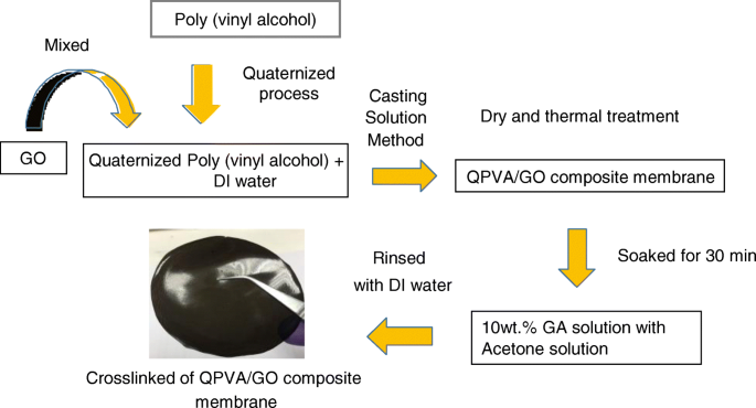
Schematische Darstellung der Herstellung der QPVA/GO-Kompositmembran
Strukturelle und morphologische Charakterisierung der Verbundmembran
Fourier-Transformations-Infrarotspektroskopie-Analyse
Infrarotabsorptionsspektren einer reinen PVA-Membran, einer reinen QPVA-Membran und einer vernetzten QPVA/GO 15 Gew. %-Kompositmembran wurden auf einer Perkin Elmer Fourier-Transform-Infrarotspektroskopie (FTIR) mit einem ATR-Modul (abgeschwächte Totalreflexion) aufgenommen. Die Proben wurden in einem Probenhalter gehalten und in das ATR-FTIR-System eingebracht. Die FTIR-Studien wurden bei Umgebungstemperatur durchgeführt und der Spektralbereich betrug 400–4000 cm −1 .
Röntgenbeugung
Röntgenbeugungsmessungen (XRD, Modell D8 Advance, Bruker AXS Deutschland) wurden von den vernetzten QPVA/GO-Verbundmembranen erhalten, um ihre Kristallinität zu untersuchen. Die Röntgenstrahlung wurde mit Cu Kα-Strahlung (Wellenlänge 0,15406 nm) von einer Anode mit einer Betriebsleistung von 40 kV und 40 mA erzeugt. Die Abtastrate betrug 0,5°s −1 , und die Auflösung betrug 0,02°. Die XRD-Spektren wurden aus Winkeln von 10° bis 50° aufgenommen.
Feldemissions-Rasterelektronenmikroskop – Energiedispersive Röntgenspektroskopie, Transmissionselektronenmikroskopie und Rasterkraftmikroskopie
Die Oberflächen- und Querschnittsmorphologien der vernetzten QPVA/GO-Kompositpolymermembran wurden mit einem ZEISS SUPRA 55 VP Feldemissions-Rasterelektronenmikroskop (FESEM) bei 10 kV betrachtet. Zur Elementkartierung wurde energiedispersive Röntgenspektroskopie (EDX) verwendet. Die trockene Membran wurde nach dem Abkühlen in flüssigem Stickstoff manuell gebrochen. Transmissionselektronenmikroskopie (TEM-Hitachi HT 7700, Japan) und Rasterkraftmikroskopie (AFM) wurden durchgeführt, um das Vorhandensein und die Größe von abgeblättertem GO zu zeigen.
Thermogravimetrische Analyse
Die thermischen Eigenschaften der Verbundmembran wurden durch thermogravimetrische Analyse (TGA) bestimmt. PVA-Membran-, QPVA-Membran- und QPVA/GO-Verbundmembran-Proben wurden von einer Umgebungstemperatur auf 600 °C unter einer Stickstoffatmosphäre in Schritten von 10 °C min −1 . erhitzt mit einem thermogravimetrischen Analysator (TGA Q500 V20.13 Build 39).
Membranaufnahme, Quellverhältnis, Ionenaustauschkapazität und oxidative Stabilität
Die Alkali-, Wasser- und Ethanolaufnahme der Membran wurde aus dem Gewichtsverlust der vernetzten QPVA/GO-Verbundmembran vor und nach der Hydratation bestimmt. Das alkalische Aufnahmeverfahren wurde durch Eintauchen der Membranprobe in 2 M KOH bei 30 °C für 24 Stunden durchgeführt. Dann wurden die Proben aus KOH entfernt, die Oberflächenfeuchtigkeit wurde mit Seidenpapier von den Proben entfernt und die Proben wurden sofort auf einer Mikrowaage gewogen, um das benetzte Membrangewicht (W nass ). Anschließend wurden die Proben in einem Ofen bei 100 °C 2 h lang getrocknet, um das getrocknete Membrangewicht (W trocken ). Die alkalische Aufnahme (W ) wurde mit der folgenden Gl. (1):
$$ W=\frac{W\ \mathrm{nass}-W\ \mathrm{trocken}}{W\ \mathrm{trocken}}\mal 100 $$ (1)Für die Wasser- und Ethanolaufnahme wurde das Verfahren modifiziert, indem die Lösungsbehandlung durch Wasser und 2 M Ethanol ersetzt wurde.
Das Quellverhältnis der vernetzten QPVA/GO-Verbundpolymermembran wurde durch Eintauchen der 100 mm 2 Proben in DI-Wasser bei 25 °C für 24 h. Dann wurde die Probe aus DI-Wasser entnommen, die Oberflächenfeuchtigkeit wurde mit Seidenpapier entfernt und die Dicke der Membran wurde gemessen, um die benetzte Membrandicke (t nass ) mit einem Mikrometer (Mitutoyo, ± 1 μm). Anschließend wurden die Proben in einem Ofen bei 100 °C 2 h lang getrocknet, um die Trockendicke (t trocken ). Das Quellverhältnis (Sr DI-Wasser ) wurde mit der folgenden Gl. (2):
$$ Sr=\frac{t\ \mathrm{nass}-t\ \mathrm{trocken}}{t\ \mathrm{trocken}}\mal 100 $$ (2)Zur Messung der Ionenaustauschkapazität (IEC) der Kompositmembranen wurde die klassische Titrationsmethode verwendet. Die Verbundmembranen wurden in einer 0,1 M NaOH-Lösung getränkt, um sie in OH − . umzuwandeln . Dann wurden die Verbundmembranen mit DI-Wasser gewaschen, um überschüssiges NaOH zu entfernen, und mit 100 ml einer 0,1 M HCl-Lösung 48 h äquilibriert. Als nächstes wurden die IEC-Werte aus der mittels Rücktitration gemessenen Säurereduktion bestimmt. Die zur Berechnung der IEC-Werte verwendete Formel (meq g −1 ) ist unten angegeben:
$$ \mathrm{IEC}\kern0.37em \left(\mathrm{meq}.{\mathrm{g}}^{\hbox{-} 1}\right)\kern0.5em =\kern0.75em \frac {M_{\mathrm{b}}-{M}_{\mathrm{a}}}{m\} $$ (3)wo M b stellt die Milliäquivalente (meq) von HCl dar, die vor dem Gleichgewicht erforderlich sind, M a stellt die nach dem Gleichgewicht erforderliche HCl dar und m ist die Masse (g) der getrockneten Verbundmembran.
Der Oxidationsstabilitätstest wurde mit dem Fenton-Reagenz (3% H2 .) gemessen O2 wässrige Lösung mit 2 ppm FeSO4 ). Die Proben (40 mm × 40 mm) wurden bei 25 °C in das Fenton-Reagenz eingetaucht. Das Gewicht der Membran vor und nach dem Eintauchen wurde nach 24 h aufgezeichnet. Jegliche Veränderungen der Membran, wenn die Probe in der Lösung zu brechen oder zu schmelzen beginnt, war der Hinweis auf die maximale Testzeit.
Ionenleitfähigkeit, Ethanoldurchlässigkeit und Selektivitätsfaktor
Die Ionenleitfähigkeit wurde mit einer Vier-Elektroden-Leitfähigkeitszelle bestimmt, die an einen Impedanzanalysator Potentiostat/Galvanostat (WonATech-WMPG1000) angeschlossen war, der verwendet wurde, um den Widerstand der Membrankomposite aus der Steigung der E-I-Kurve zu erhalten [47]. Alle Messungen wurden mit Gl. (4):
$$ \sigma =\frac{L}{RS} $$ (4)wobei σ, L , R , und S repräsentieren die Protonenleitfähigkeit (σ, S cm −1 ), der Abstand zwischen den Gegenelektroden (L, cm), der Widerstand der Membranen (R, S −1 ) und die Querschnittsfläche der Membranproben (S, cm 2 ), bzw. Die vernetzten PVA/GO-Kompositmembranen wurden in entionisiertem Wasser bei verschiedenen Temperaturen (30–60 °C) äquilibriert. Die Membranen wurden in Querrichtung positioniert und zwischen die Elektroden gelegt.
Eine Diffusionszelle mit zwei Glaskammern wurde gebaut, um die Ethanolpermeabilität der Membran zu bestimmen. Die Gläser mit zwei Kammern wurden geteilt, um die Zufuhrkammer zu bilden, die mit 2 M, 4 M, 6 M oder 8 M Ethanol gefüllt war, und eine zweite Kammer, die mit entionisiertem Wasser gefüllt war. Jede Kammer enthielt einen Magnetrührstab zum Rühren der Lösung. Die Membran wurde vertikal zwischen den beiden Glaskompartimenten eingespannt [47]. Während des Experiments wurde die Konzentration von Ethanol gemessen, das die Membran durchquerte. Die Membranpermeabilität wurde unter Verwendung der folgenden Gl. (5):
$$ P=\frac{1}{Ca}\left(\frac{\Updelta Cb(t)}{\Updelta t}\right)\left(\frac{LVb}{A}\right) $$ ( 5)wo P repräsentiert die Ethanol-Diffusionspermeabilität der Membran (cm 2 s −1 ), Ca steht für die Konzentration der Fütterungskammer in Zelle A (mol L −1 ), ∆Cb (t )/∆t stellt die Steigung der molaren Variationen der Ethanolkonzentration in Zelle B als Funktion der Zeit dar (mol L −1 s), Vb repräsentieren das Volumen in jedem der Diffusionsreservoirs (cm 3 ), A die Membran darstellen und L repräsentieren die Dicke der Membran (cm). Die gesamte Konzentrationslösung wurde mit einem Refraktometer gemessen. Der Selektivitätsfaktor der vernetzten QPVA/GO-Kompositpolymermembranen (das Verhältnis der Ionenleitfähigkeit zur Ethanolpermeabilität) wurde unter Verwendung der folgenden Gl. (6) und (7):
Selektivität,
$$ \Phi =\frac{P}{\sigma} $$ (6)Einzelzelle des passiven Alkaline-DEFC-Leistungs- und Haltbarkeitstests
Abbildung 2 zeigt die Einzelzelle des selbstgebauten passiven Alkali-DEFC und die Membran-Elektroden-Einheit (MEA). Die MEA für die passive Alkali-DEFC-Testzelle wurde konstruiert und die Verbundmembran wurde zwischen beiden Elektroden (der Anode und Kathode) über eine Heißpressmaschine sandwichartig angeordnet. Für die Anode wurde ein Pt-Ru-Katalysator mit 4 mg cm –2 . aufgetragen , und für die Kathode wurde ein Pt-Katalysator mit 4 mg cm –2 . aufgetragen zu einer Gasdiffusionsschicht aus Kohlepapier über eine manuelle Gießtechnik. Pt-Ru und Pt wurden von Alfa Aesar, USA, geliefert. Die DEFC-Leistung wurde durch passive Luftatmung mit einem selbstgebauten Einzelzellenstapel mit einer aktiven MEA-Fläche von 4 cm 2 . getestet . Der Brennstoffreservoirbereich des Einzelzellenstapels lässt 2 ml Brennstoff zu. Die Polarisationsdaten wurden unter Verwendung des Potentiostaten/Galvanostaten (WonATech) erhalten, um die Spannungsantwort durch Anlegen des Laststroms an eine einzelne Zelle unter Umgebungsbedingungen zu messen. Als nächstes wurden 2 M KOH + 2 M Ethanol als Brennstoff im anodischen Reservoir umgesetzt und die Umgebungsluft diffundierte während des Leistungstests in die Kathodenöffnung. Die Einzelzelle der Passiv-Alkali-DEFC wurde einem Haltbarkeitstest über einen Zeitraum von 1000 h bei 60 °C unterzogen. Aufgrund der passiven Kraftstoffzufuhr muss die Ethanollösung alle 12 h nachgefüllt werden. Der Haltbarkeitsleistungstest wurde im Dauerbetrieb mit konstanter Last durchgeführt, wobei die Zellspannung konstant bei 0,3 V lag. Nachdem der Haltbarkeitstest beendet war, wurde der Polarisationstest einer einzelnen Zelle wiederholt, um die Leistung zu vergleichen.
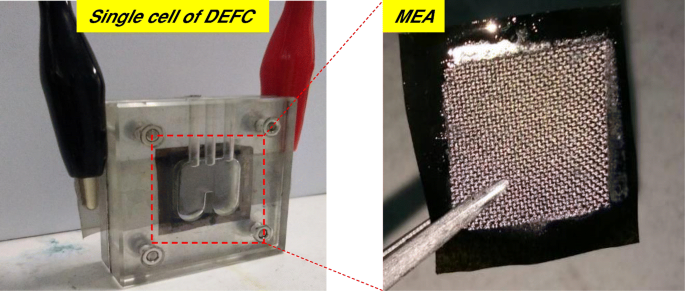
Die Einzelzelle von Passiv-Alkali-DEFC und MEA
Ergebnisse und Diskussion
Charakterisierung und Morphologie der Verbundmembranen
Der Quaternisierungsgrad beträgt 2,6% und die restlichen 97,4% sind Matrixpolymer von PVA [23]. Es wurden sechs verschiedene Membrantypen hergestellt; reine PVA-Membran, vernetzte QPVA-Membran und vier vernetzte QPVA/GO-Verbundmembranen mit unterschiedlichem Gewichtsprozentsatz, 5 Gew. %, 10 Gew. %, 15 Gew. % bzw. 20 Gew. %. Tabelle 1 listet das Ergebnis der Elementarkartierung der unberührten PVA-Membran und der vernetzten QPVA/GO 15 Gew. %-Kompositmembran durch EDX-Spektroskopie auf. Die PVA-Verbundmembran enthielt Kohlenstoff (C) und Sauerstoff (O). Inzwischen enthielten die vernetzten QPVA/GO 15 Gew.-% Verbundmembranen Kohlenstoff (C), Stickstoff (N) und Sauerstoff (O), was darauf hinweist, dass die quaternäre Ammoniumgruppe erfolgreich in die PVA-Matrix gepfropft wurde. Die Einführung von GO in QPVA verursachte eine Zunahme des Gewichts und des Atomprozentsatzes von O innerhalb der Verbundmembran aufgrund der sauerstoffhaltigen funktionellen Gruppen von GO (Hydroxyl-, Carboxyl- und Epoxygruppen). Die Beweise, die das Engagement von QPVA und GO stützen, wurden mit Schwingungsspektroskopie aus der FTIR-Analyse weiter untersucht. Die funktionellen Gruppen von PVA, QPVA und QPVA/GO 15 wt. % Composite-Membranen wurden im Bereich von 400–4000 cm −1 . aufgezeichnet , wie in Abb. 3 gezeigt.
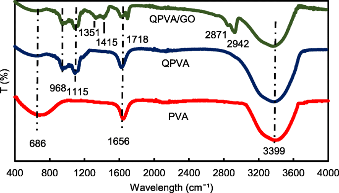
FTIR-Spektren mit Wellenlänge 400–4000 cm −1
Abbildung 3 zeigt den Wellenlängenbereich von 400 bis 4000 cm −1 . Der Absorptionspeak bei 686 cm −1 in der PVA-Membran entspricht der aliphatischen C-H-Biegung [3]. Nach dem Quaternisierungs- und Vernetzungsprozess wurde die aliphatische C-H-Biegung reduziert, und im Spektrum der vernetzten QPVA-Membran und der vernetzten QPVA/GO-Kompositmembran mit 15 Gew.-% traten mehrere neue Peaks auf. Der Peak bei 968 cm −1 wurde als aliphatisches C-N charakterisiert, was darauf hinweist, dass die quartäre Ammoniumgruppe auf das Rückgrat des Matrixpolymers aufgepfropft wurde [31]; und der Peak bei 1115 cm −1 geben die C–O–C-Streckgruppe an, die nach der Vernetzungsbehandlung erschien und beweist, dass die Vernetzungsreaktion stattgefunden hat und dass die Kompositmembran erfolgreich durch GA vernetzt wurde [12]. Es gibt mehrere neue Peaks, die in der Verbundmembran im Vergleich zu reinem PVA und vernetztem QPVA erscheinen; der Peak bei 1351 cm −1 repräsentiert Epoxy-C-O-symmetrische Schwingungen von GO [23]; der Peak bei 1415 cm −1 stellt die Streckschwingungen von Carboxylgruppen (O=C-O) von GO dar [44]; die Verformung des Peaks bei 1656 cm −1 zurückzuführen auf die integrierte C=C-Streckung von der aromatischen Struktur, die dem sp 2 . entspricht Charakter der hydrophoben GO-Region und Reaktion des Rückgrats des Matrixpolymers [39]; der neue Peak bei 1718 cm −1 resultiert aus -COOH-Streckung in der Carboxylgruppe im GO [23]; die neuen Peaks erscheinen in der Verbundmembran bei 2871 cm −1 , die zu =C–H Dehnung gehören und bei 2942 cm −1 , die Zunahme der asymmetrischen und symmetrischen Streckung von –CH2 vom GO aus beobachtet werden kann. Nach der Modifikation von PVA eine starke und breite Absorption bei 3399 cm −1 kann aufgrund der Abschwächung der –OH-Streckung beobachtet werden, die durch die Bildung von Wasserstoffbrücken mit der funktionellen Gruppe von GO beeinflusst wird. Aus der FTIR-Spektralanalyse zeigten die Peaks des Quaternisierungsprozesses von PVA und der Synthese von GO deutlich funktionelle Gruppen und hydrophobe Bereiche, ähnlich wie in früheren Studien [23, 31, 44], was darauf hindeutet, dass die vernetzte QPVA/GO-Kompositmembran erfolgreich war synthetisiert.
Eine Röntgenbeugungsmessung wurde durchgeführt, um die Kristallinität der Verbundmembran zu beobachten. Die Abbildungen des Beugungsmusters für den XRD-Analysepeak sind in Abb. 4a, b dargestellt. Leeet al. [43] hat berichtet, dass der Graphitpeak bei 25,6° liegt. Abbildung 4a zeigt die XRD-Spektren von selbstgemachtem GO mit der progressiven Phasenänderung von Graphit zu GO. Die Peakintensität ist mit 10,92° etwas höher, da GO nach dem Oxidationsprozess abgeblättert ist. Die Änderungen treten aufgrund der Wechselwirkung zwischen der hydrophoben Region mit der dispergierten sauerstoffhaltigen funktionellen Gruppe am Rand der GO-Benzolstruktur auf [43]. Das Vorhandensein eines großen Peaks im XRD-Muster bei 19–20° und der kleine Peak bei 39–40° waren Indikatoren für die halbkristalline Struktur von PVA, wie in Abb. 4a gezeigt. Die Peakintensität von QPVA bei 19–20° war im Vergleich zu reinem PVA aufgrund der Einführung einer funktionellen Ammoniumgruppe, die die halbkristalline PVA-Struktur störte, verringert. Daher wird der amorphe Bereich zu einer Domäne in der QPVA-Polymermatrix. Diese Struktur hat zur Verbesserung der Ionenleitfähigkeit aufgrund der Zunahme der freien Volumina in der Polymerkette beigetragen, die mehr freien Raum bereitstellen, der als Ionenpfad durch die Membran mit der lokalen strukturellen Relaxation und den Segmentbewegungen des Polymers fungiert [26]. Abbildung 4b zeigt, dass der große Beugungspeak von GO unsichtbar war, was darauf hindeutet, dass GO durch physikalische Wechselwirkung homogen in der QPVA-Matrix dispergiert war. Bemerkenswerterweise war der GO-Peak bei 2θ = 10,92° aufgrund der vollständigen Abblätterung und Zerstörung der Originalfolie durch Einbau in das QPVA-Polymer fast unsichtbar. Dieses Ergebnis bestätigte, dass die Synthese einer vernetzten QPVA/GO-Kompositmembran die Bildung von Wasserstoffbrücken und die Wechselwirkungen auf ionischer Ebene zwischen den Polymerketten und den funktionellen Gruppen in GO beinhaltet [23, 39]. The diffraction intensity of the QPVA at 19–20° was still detected, implying that the degree of QPVA crystallinity was maintained until the additional of graphene oxide at 20 wt.% loading. Hence, the chemical structure of the QPVA composite films barely changed as the graphene oxide loading increased, indicating that there were many physical interactions but few chemical reactions occurring between the QPVA and graphene oxide in the composite membrane formation process [39, 48]. In addition, the amorphous structure of composite membrane has significant effect in ionic conductivity due to the formation of free volume by constantly fragmental movement of the polymer matrix. Thus, the presence of GA as a crosslinked and KOH as a doped inside the polymer matrix provided more pathway for ionic to pass through the membrane [27, 49,50,51].
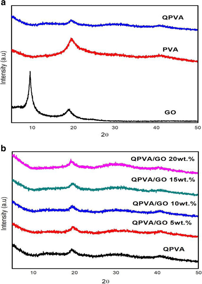
XRD-Muster von a GO, PVA, and QPVA; b QPVA, QPVA/GO composite membrane
The FESEM, TEM, and AFM images were used to identify the morphological features of GO as shown in Fig. 5. Figure 5a, b shows the FESEM and TEM images which clearly seems that the single layer of graphene oxide (likes a paper sheet) was successfully exfoliated from the graphite flakes. AFM was used to measure GO layer thickness of 0.87 nm as presented in Fig. 5c. The GO thickness obtained has confirm the exfoliated single layer of GO has successfully synthesized. The morphologies of the prepared membrane are shown in Fig. 6a–d by FESEM at a magnification of × 10.00 k. All the top view of FESEM images show that all membranes are dense and remain uncrack, although there are annealing in 100 °C, which proves the excellent chemical stability due to the cross-linkage and modification with GO in QPVA matrix. This characteristic is important for using as polymer electrolyte membrane in DEFC applications, especially to prevent the fuel crossover. The surface of the PVA membrane seems very smooth as shown in Fig. 6a, while the QPVA membrane in Fig. 6b shows a different morphology, as the grain distribution obviously appeared, indicating that the PVA was successfully grafted with quaternary ammonium groups [27]. Figure 6c shows the top view of the QPVA/GO composite membrane, indicating the random distribution of GO inside the QPVA which proved that GO has successfully exfoliated and dispersed throughout the membrane. From the cross-sectional view in Fig. 6d, the composite membrane exhibit a dense and compact structure with high homogeneity, indicating the unification of QPVA and GO in the composite membrane without any holes. In addition, the presence of GA and KOH filled the free volume inside the polymer matrix. This is the important characteristics for separation and fuel crossover reduction. Hence, the homogeneous exfoliation of GO, dispersion of GA and KOH improve the ionic conductivity and reduce the ethanol permeability [23, 24, 52, 53].

FESEM, TEM, and AFM image of exfoliated graphene oxide
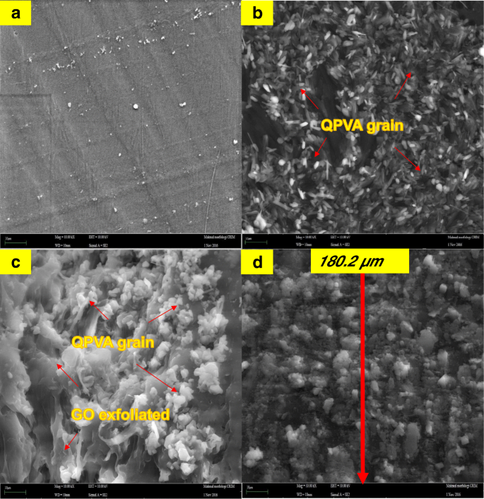
FESEM image of a surface PVA membrane, b surface QPVA membrane, c surface of QPVA/GO composite membrane, and d cross section of QPVA/GO composite membrane
Thermal Stability
The thermal stability of the crosslinked QPVA/GO composite membrane was illustrated by TGA studies. Figure 7 shows the TGA curves for the pure PVA membrane, QPVA membrane, and QPVA/GO 15 wt.% composite membrane. The TGA curves of these three membranes present three major weight loss regions. The first region is at 70–130 °C due to the loss of adsorbed water in the membrane through the evaporation of the weak and strong physical and chemical bonds of water, respectively. The weight loss of all membranes is approximately 5–8 wt.%. The second transition region of weight loss at approximately 230–320 °C is ascribed to the decomposition of the side chains of the matrix polymers. The weight loss of the membrane was 75 wt.% for PVA, 70 wt.% for QPVA, and 60 wt.% for QPVA/GO; the total weight loss of PVA was the highest due to the presence of fewer side chain groups compared to QPVA/GO. The third transition region of weight loss at approximately 430–480 °C was ascribed to the decomposition of the main chain of the membrane due to cleavage of the C–C backbone of the matrix polymers. At 600 °C, the residual mass of the PVA membrane was 4.7 wt.%. The residual mass of the QPVA membrane and the QPVA/GO membrane were 7.67 wt.% and 22.2 wt.%, respectively.
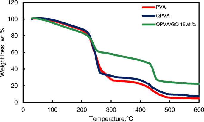
TGA analysis of PVA membrane, QPVA membrane and QPVA/GO composite membrane
Figure 7 shows that the weight loss of the QPVA/GO 15 wt.% membrane was less than the other membranes; this result indicates that the quaternization process of the PVA matrix and the incorporation of GO inside the composite membranes was successful. The inorganic filler enhanced the thermal stability of the composite membrane and produced a strong network between the matrix polymer and the GO filler reinforcement. In addition, the chemical crosslink reaction by glutaraldehyde assists in the enhancement of thermal stability.
Alkaline Uptake, Swelling Ratio, and Oxidative Stability
Alkaline uptake is the major process for electrolyte preparation. The KOH used for alkaline doping serves as a charge carrier and cross-linker. The alkaline–DEFC was operated with alkaline anode fuel (alcohol in KOH solution). Alkaline uptake in the membrane is important for providing OH − Ionen. The optimal KOH uptake condition is necessary to provide high ionic conductivity. Nevertheless, excessive KOH uptake leads to the deformation of the matrix polymer and degrades the mechanical stability of alkaline–DEFC by shortening its lifetime. The dry membrane films were immersed in 2 M KOH at 30 °C, and the dimensional stability was estimated using the changes of the membrane weight for alkaline uptake and the width, length, and thickness for the swelling ratio of the membrane films before and after doping with 2 M KOH. Table 2 shows that the alkaline uptake of the PVA membrane was 105%. After the quaternization process, the hydrophilic structure C–H and the presence of quaternary ammonium groups led to an alkaline uptake of QPVA membrane increase up to 136%. However, the introduction of GO in QPVA associated the reduction of alkaline uptake until to 45% with 20 wt.% loading of GO. The hydrophobic region of GO contributes a “blocking effect” in the polymer matrix and thus reduced the KOH absorption of the membranes. Furthermore, the crosslinking agent might also reduce the alkaline uptake due to the more compact network structures formed in the composite membranes [23, 50]. The alkaline uptake has influence the swelling behavior of the composite membranes.
The in-plane swelling (i.e., width and length) and through-plane swelling (i.e., thickness) ratios of the composite membranes are shown in Table 2. Generally, a low membrane swelling ratio is favorable for tolerating the dimensional match between the electrode and membrane; thus, the stable formation of MEA is encouraged during single cell performance. The in-plane and through-plane swelling ratios for the QPVA membrane were 18% and 60%, respectively. The introduction of GO up to 20 wt.% loading into QPVA reduced the in-plane and through-plane swelling ratios to 7.54% and 32%, respectively. The introduction of GO not only favors the formation of connected ionic transport channels but also expands the hydrophobic region of GO inside the matrix QPVA, which results in the dimensional stability of the composite membranes [23, 52]. The crosslinked QPVA/GO 20 wt.% composite membrane showed lower swelling ratios than the pristine QPVA membrane. Liao et al. [26] reported a low in-plane swelling ratio due to the strong interactions between the polymer matrix and filler, which involve dipole-dipole interactions, hydrogen bonding, and van der Waals interactions between the polymer and GO. All the samples exhibit good in-plane swelling ratios rather than through-plane swelling ratios, which are beneficial for the MEA contact conditions.
The oxidative stability of the anion exchange membrane was measured in the Fenton’s reagent test which is known as hastened oxidative stability test. Table 1 shows the retained weight percentage of the crosslinked QPVA/GO membranes. After 24-h immersion, the retained weight of the QPVA membrane is 97%. It was slightly declined with increasing of GO loading which retained weight of 91% for 20 wt.% of GO. The obtained results demonstrated that the free radicals have little impact on the QPVA-based membranes due to the greater oxidative resistivity of hydrogen bond formed between GO, GA, and polymer matrix. This may be due to the presence of oxygen contained functional groups present in the GO that easily forms hydrogen bonding with pristine QPVA [1, 23, 54]. The weight loss percentage results indicate that the crosslinked QPVA/GO membrane has good oxidative stability against Fenton’s reagent.
Water Uptake, Ion Exchange Capacity, and Ionic Conductivity
Water uptake is an important parameter for ionic transfer inside the electrolyte membrane. But, higher of water uptake will degrade the membrane performance [8, 50]. From the Fig. 8, the modification of QPVA-based membrane and GO has successfully reduce the water uptake form 145 to 46%. Ion exchange capacity (IEC) is an important parameter for evaluating the mobility ability of anion through the membrane. Besides, IEC is useful to determine the range of optimal water uptake which enhance the conductivity of membrane through the vehicle mechanism [33, 55]. Figure 8 shows that the values of the experimental IEC ranged from 1.05 to 2.71 meq g −1 according to the increase of GO loading. The existence of quaternary ammonium group grafts on matrix polymer and increasing amounts of GO has led to the addition of oxygenic functional groups, including hydroxyl, carboxyl, and epoxy groups, which are useful for anion transfer through the Hopping @ Grotthus mechanisms [22, 35]. Higher IEC values are the main indicator of higher ionic conductivity due to the high charge density inside the membrane [33, 55].
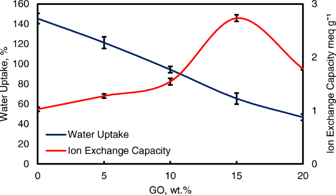
Water uptake and IEC analysis of QPVA membrane and QPVA/GO composite membrane at 30 °C
Figure 9 also shows the ionic conductivities of the QPVA membrane and the crosslinked QPVA/GO composite membrane at 30 °C. The ionic conductivity of the QPVA membrane (4.7 × 10 −3 S cm −1 ) is higher compared to the PVA membrane (1.05 × 10 −3 S cm −1 ). The grafted quaternary ammonium group at the PVA backbone assists in increasing the ionic conductivity due to the OH − that has been transferred effectively through the pathway created by the presence of functional groups in GO [31]. The ionic conductivity of composite membranes was increased which recorded as 7.3 × 10 −3 S cm −1 , 11.3 × 10 −3 S cm −1 , and 17.56 × 10 −3 S cm −1 for GO loading at 5 wt.%, 10 wt.%, and 15 wt.%, respectively. The introduction of GO in the composite membrane up to 10 wt.% showed a slight increase in ionic conductivity attributed to the “blocking effect” of the GO sp 2 characteristic reacting as a hydrophobic region for ionic clusters in the composite membrane.
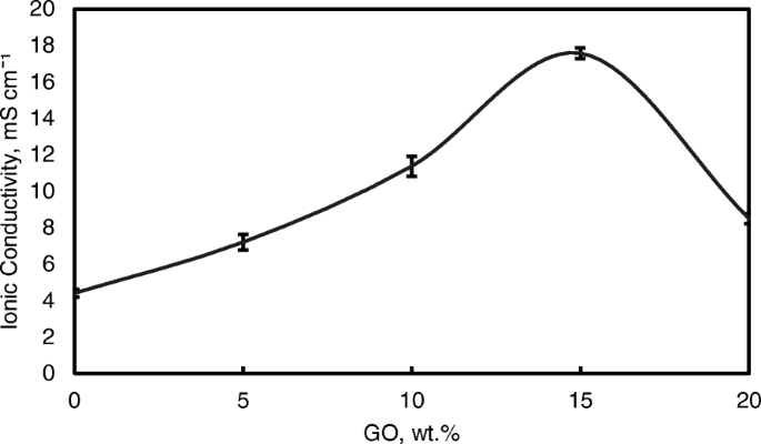
Ionic conductivity analysis of QPVA membrane and QPVA/GO composite membrane at 30 °C
However, beyond 10 wt.% of GO loading (15 wt.%), the ionic conductivity of the composite membrane increased to 17.35 × 10 −3 S cm −1 due to the sufficiently highly oxygenated functional groups (hydroxyl, carboxyl, and epoxy) in GO to provide alternative anion pathways as well as overwhelming the blocking effect from the hydrophobic region. Thus, the addition of GO has enhance the ionic conductivity of the composite membranes [43]. The oxygenic functional groups of GO, such as carboxyl groups, can form complexes with KOH molecules and form good ionic conductors with high-speed channels for anion exchange and transport. This condition is useful for hopping mechanism [23, 52]. Moreover, the strong interactions between GO, the polymer matrix, and GA form a three-dimensional network that can hold water and alkaline molecules that are important in the Vehicle mechanism. Ionic transport depends on the alkaline molecules and water uptake occurs by the vehicle mechanism. In the composite membranes, the alkaline molecules could be classified as free alkaline and bound alkaline. For conductivity, only the free alkaline affects the anion transport [23, 56]. Figure 10a presents the ionic transport illustration for crosslinked QPVA/GO composite membrane.
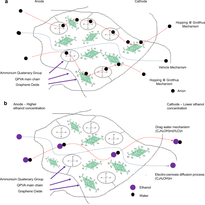
a Illustration of ionic transfer for the crosslinked QPVA/GO composite membrane. b Illustration of ethanol transfer for the crosslinked QPVA/GO composite membrane
However, when the GO loading exceeded 20 wt.%, the ionic conductivity of the composite membrane declined due to the decrease in alkaline uptake by the composite membrane, which was attributed to the GO hydrophobic region. Hence, this condition disturbs the Grotthuss mechanism in conveying the ionic diffusion, thus reducing the ionic conductivity of the composite membrane. Higher temperature increases the ionic conductivity due to the effect of fast anion mobility. In addition, the distance between the polymer chains becomes larger at higher temperature, providing more free volume and facilitating water molecule movement to enhance anion conductivity [1, 45]. Figure 11 shows the trend of the ionic conductivity when the temperature increased. Increasing temperature also led to increasing ionic conductivity. The highest ionic conductivity was 4.6 × 10 −2 S cm −1 at 60 °C for 15 wt.% GO loading. Compared to the previous study on PVA-based membranes in DEFCs, such as PVA/HPW/DPTA, PVA/TMAPS, PVA/LDH, and PVA/CNTs [11,12,13, 50], the current QPVA/GO membrane showed the highest ionic conductivities.
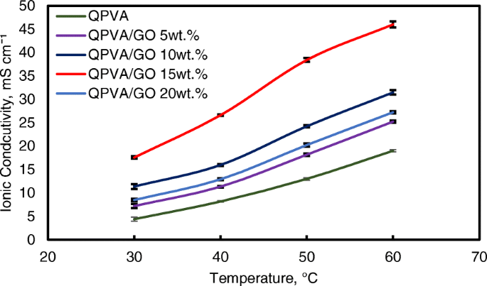
Ionic conductivity analysis of QPVA membrane and QPVA/GO composite membrane at different temperature
The ln σ and 1000/T plots are shown in Fig. 12 with the assumption that the ionic conductivity follows Arrhenius behavior. The activation energy E a of the transferred ion in the composite membranes can be obtained according to the Arrhenius equation:
$$ {E}_a=-b\times R $$ (7)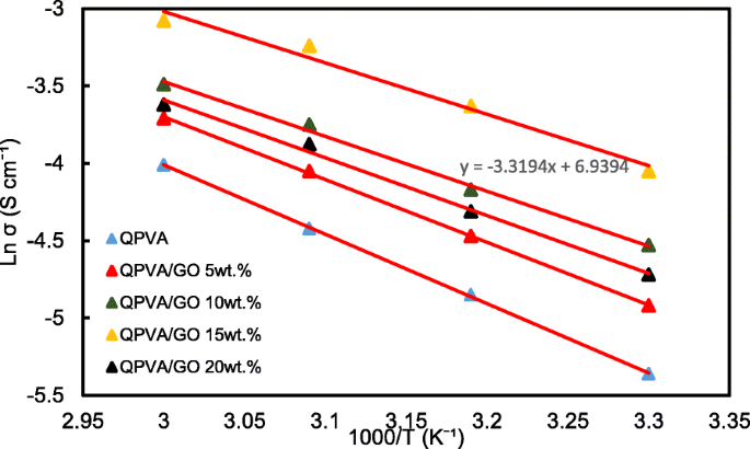
Ln σ vs. 1000/T plot for the QPVA/GO composite membrane; the lines indicate the linear regression
wo b is the slope of the regression line for the plotted graph (ln σ vs.1000/T) and R represents the gas constant (8.314472 J K −1 mol −1 ). The QPVA/GO 15 wt.% composite membrane has the lowest activation energy of 18.11 kJ mol −1 compared to the other composite membranes. The GO loading at 15 wt.% resulted in sufficient presence of functional groups in the composite membrane, also providing an optimal structure for the effective anion transport to subsequently contribute to the reduction of the activation energy.
Ethanol Uptake and Ethanol Permeability
Figure 13 shows the ethanol uptake and ethanol permeability of the pristine QPVA and the crosslinked QPVA/GO (5–20 wt.%) composite membrane in 2 M ethanol at 30 °C. One PVA property is its slight solubility in ethanol, which effectively reduces ethanol crossover [57]. The ethanol uptake clearly indicates that the QPVA polymer absorbs less ethanol than water. With 20 wt.% GO loading, ethanol uptake decreased by ~ 35% (from 52% by the pristine QPVA membrane to 34% by the crosslinked QPVA/GO 20 wt.% composite membrane). This behavior can be explained by the possible appearance of a three-dimensional network built by the crosslinking effect of GA on GO and the polymer matrix. These results are important because they can indicate the dimensional stability of the composite membranes under the set conditions and show their barrier properties and ethanol permeability. The reduction in ethanol uptake was mainly provided from the optimum GO loading, which increased the formation of a three-dimensional network between GA, GO, and PVA. Thus, the free volume of the polymer composite decreased and thus resisted the ethanol mobility pathway [12, 50, 55]. Figure 13 shows similar result of ethanol permeability for the pristine membrane and composite membranes. The ethanol permeability of the membrane decreased by ~ 85% (from 8.7 × 10 −7 cm 2 s −1 for the pristine membrane to 1.32 × 10 −7 cm 2 s −1 for the crosslinked QPVA/GO 20 wt.% composite membrane). The reduction of ethanol permeability is affected by increasing the GO content of the composite membrane. The three-dimensional network between GA, GO, and PVA formed a compact structure that increased the resistance of the membrane to ethanol crossover. Besides, the presence of KOH as electrolyte was fulfilled the free volume space in polymer matrix [24, 50, 55]. Figure 10b has illustrated the ethanol transport in crosslinked QPVA/GO composite membrane. The ethanol permeability of the composite membranes has also been studied in different ethanol concentrations (2, 4, 6, and 8 M) at 30 °C, as shown in Fig. 14. The result showed that the ethanol permeability is lower in order of range ~ 10 − 7 cm 2 s −1 . The reduction in ethanol permeability was attributed to the presence of the hydrophobic region when the GO content increased, which functions as an ethanol crossover blockage [55, 58]. At the same temperature, the crosslinked QPVA/GO composite membrane exhibited lower ethanol permeability than the PVA/phosphotungstic acid solutions, with different percentages of diethylenetriaminepentaacetic acid. The ethanol permeability of the crosslinked QPVA/GO composite membrane is in the range of 1.32–8.7 × 10 −7 cm 2 s −1 , which is lower than the previous study using QPVA with fume silica (14–16 × 10 −6 cm 2 s −1 ) in 3 M and 5 M ethanol [40]. The ethanol permeability increased with increasing in ethanol concentration. This result is the initial indicator that the open-circuit voltage of a single cell with this composite membrane will decrease with increasing ethanol concentration.
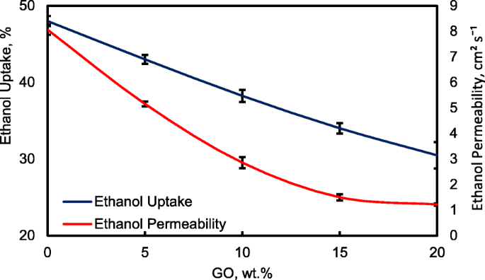
Ethanol uptakes and Ethanol permeability of QPVA membrane and QPVA/GO composite membrane at 30 °C
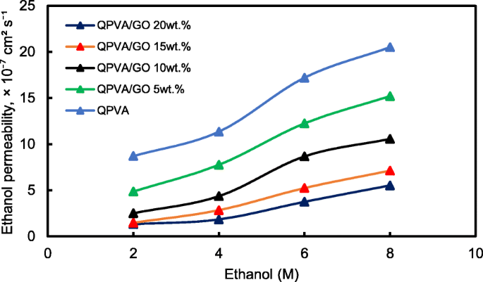
Ethanol permeability of QPVA membrane and QPVA/GO composite membrane with different ethanol concentration
The crosslinked QPVA/GO composite membrane with the highest ionic conductivity (15 wt.% QPVA/GO) at 30 °C was particularly observed in the ethanol permeability test for various temperatures to assess its performance for portable devices in the range of 30 °C to 60 °C, as shown in Fig. 15. The higher temperature leads in higher ethanol permeability due to the interaction between the membrane chains become more active. In addition, the free volume inside the membranes started to extend, which reduced the resistance for ethanol crossover. The diffusion cell was measured in a steady state without any electrical current. When the composite membrane was applied in DEFCs, the practical ethanol permeability was lower due to the movement of anion transport opposite of the direction of ethanol crossover from the anode to the cathode [8, 52].
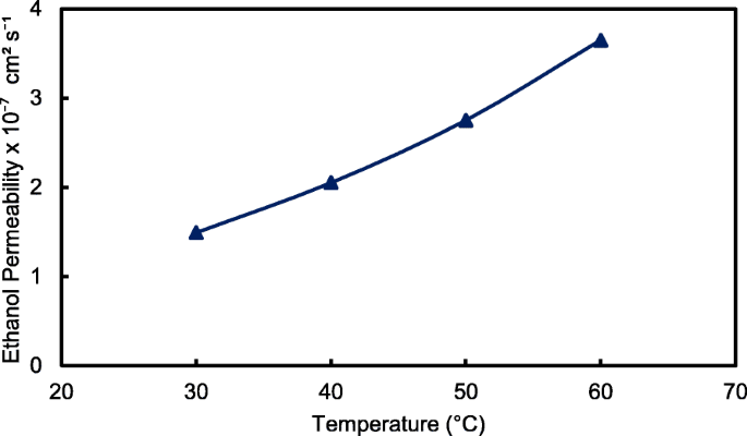
Ethanol permeability of QPVA/GO 15 wt.% composite membrane with different temperature
Selectivity of the Membrane, the Passive Alkaline–DEFC Performance and Durability Test
For the excellent single-cell application of passive alkaline–DEFCs, the membrane should have high ionic conductivity and low ethanol permeability. The ratio of both tests is called the selectivity factor. An excellent performance of a composite membrane is associated with a higher selectivity factor [55]. The selectivity of the composite membranes is presented in Fig. 16. The behavior was caused by the modification of QPVA and the introduction of GO with 15 wt.% loading due to the highest conductivity and the lowest ethanol permeability achieved. Therefore, this membrane has potential for further studies in single-cell alkaline–DEFCs. Table 3 shows a comparison between the ionic conductivity, ethanol permeability, and selectivity factor for PVA-based membranes in passive DEFC applications at 30 °C. The present study shows a comparable performance with the other previous works.
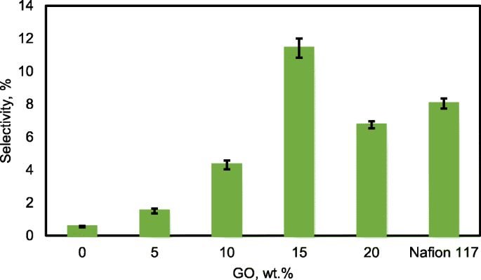
Selectivity of QPVA membrane, QPVA/GO composite membrane and Nafion 117
Figure 17 illustrates the polarization and power density curves for passive alkaline–DEFCs at 30 °C for crosslinked QPVA, crosslinked QPVA/GO 15 wt.%, and Nafion 117 membranes. Obviously, the crosslinked QPVA/GO 15 wt.% composite membrane exhibited a higher open-circuit voltage (OCV) of 0.61 V, which can be attributed to the low ethanol permeability compared to QPVA and Nafion 117, which only reach OCV values of 0.54 V and 0.51 V, respectively. The OCV result was similar with previous study which used the platinum-based catalyst for the single cell test performance, in the range of 0.4 V to 0.6 V [15, 59, 60]. The lower concentration of fuel affected the OCV value, and Yuen et al. [61] reported for the best concentration for passive cell which used platinum catalyst based must be higher than 4 M to achieve the optimum cell performance. The maximum power density of the crosslinked QPVA/GO 15 wt.% composite membrane was 9.1 mW cm −2 , which was higher than QPVA and Nafion 117 of 5.88 mW cm −2 and 7.68 mW cm −2 , bzw. These results prove that the interaction between QPVA and GO occurred and was powerful to improve the potential of these membranes.
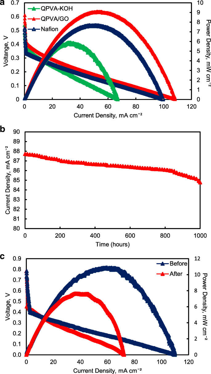
a Cell voltage and power density vs. current density curve obtained for the passive alkaline–DEFC. b Durability test on passive alkaline–DEFC. c Cell voltage and power density vs. current density curve before and after 10,000 min of durability test. Anode feed; 2 M KOH + 2 M ethanol, vathode feed; Air:a at 30 °C; b , c at 60 °C
The performance of cell current density throughout the durability test operation at 60 °C was shown in Fig. 17b. The passive alkaline–DEFC was operated for 1000 h at a constant voltage of 0.3 V continuously. The current density of cells start with 87.7 mA cm −2 and was decreased continuous slowly until 1000 h operation and finally reaching approximately 84.7 mA cm −2 at 1000 h. This performance decreased steadily may be caused by the increasing of ethanol permeability which attributed the enhancement of fuel crossover without oxidation activity, which was significant negative effect on single cell performance [62]. The durability test results show high efficiency operation of crosslinked QPVA/GO 15 wt.% composite membrane in single cell which the sustainable performance until 1000 h.
Figure 17c shows the change of performance in cell voltage and power density of the crosslinked QPVA/GO 15 wt.% composite membrane before and after durability testing to evaluate the permanent degradation of alkaline passive–DEFC. When the operation temperature of single cell increase 60 °C, the OCV of cell increase to 0.78 V and the maximum power density of the crosslinked QPVA/GO 15 wt.% composite membrane increase 11.4 mW cm −2 . After the durability testing, the maximum power density reduced to 7.65 mW cm −2 . The dropped of power density was subjected to activation loss of catalyst activity due to ethanol crossover and the loss of maximum power density was 32.8%. The power loss depended on the current density drawn from the single cell. However, the value of OCV after the 1000 h test presented no significant reduction compared to before durability test [63].
Table 3 presents a comparison of PVA-based membranes previous study applied in passive DEFCs using a Pt-based catalyst. The performance in this study was higher than that of the passive DEFCs reported by Yang et al. [14] (8 mW cm −2 ) and higher than the optimization of commercial Nafion®117 membranes in passive DEFCs reported by Pereira et al. [5] (1.33 mW cm −2 ). This result demonstrated the success of our study targeting the performance of passive alkaline–DEFCs using crosslinked QPVA/GO composite membrane as alternative membrane for commercial membrane.
Conclusion
New composite membrane was prepared by blending the QPVA polymer as a matrix and GO as a filler using GA as a crosslinking agent. The existence of a quaternary ammonium group grafted on PVA and modified with GO was confirmed by FTIR, XRD, and FESEM-EDX analysis. With the formation of three-dimensional networking between the polymer matrix, GO, and the crosslinking agent, the thermal stability of the composite membrane was enhanced. The highest ionic conductivity achieved was 0.046 S cm −1 , along with a low ethanol permeability of 1.48 × 10 7 cm 2 s −1 . The maximum power density of 9.1 mW cm −2 was observed for the crosslinked QPVA/GO 15 wt.% composite membrane at 30 °C and 11.4 mW cm −2 at 60 °C. Therefore, the crosslinked QPVA/GO composite membrane has high potential for use in single-cell DEFC applications. The process of optimizing the composition of QPVA/GO and the replacement of the non-Pt catalyst are expected to further enhance the performance of the QPVA/GO composite membrane.
Abkürzungen
- A:
-
Membrane
- AFM:
-
Rasterkraftmikroskopie
- C:
-
Carbon
- Ca:
-
Concentration of the feeding chamber in cell A
- DEFC:
-
Ethanol fuel cell
- EDX:
-
Energiedispersive Röntgenspektroskopie
- FESEM:
-
Feldemissions-Rasterelektronenmikroskop
- GO:
-
Graphenoxid
- GTMAC:
-
Glycidyltrimethyl-ammonium chloride
- H2 O2 :
-
Hydrogen peroxide
- H2 SO4 :
-
Sulfuric acid
- H3 PO4 :
-
Phosphoric acid
- HCL:
-
Hydrochloric acid,
- KOH:
-
Potassium hydroxide
- L:
-
Distance between the counter electrodes
- L:
-
Thickness of the membrane
- m:
-
Mass (g) of the dried composite membrane.
- Ma :
-
HCl required after equilibrium
- Mb :
-
HCl required before equilibrium
- N:
-
Nitrogen
- NaOH:
-
Sodium hydroxide
- O:
-
Oxygen
- P:
-
Ethanol diffusion permeability of the membrane
- PVA:
-
Poly (vinyl alcohol)
- QPVA/GO quaternized:
-
Poly (vinyl alcohol)/graphene oxide
- R:
-
Resistance of the membranes
- t nass :
-
Thickness
- TEM:
-
Transmissionselektronenmikroskopie
- TGA:
-
Thermogravimetrische Analyse
- Vb:
-
Volume in each of the diffusion reservoirs
- XRD:
-
Röntgenbeugung
- σ:
-
Proton conductivity
Nanomaterialien
- Mit Titanat-Nanoröhren dekorierte Graphenoxid-Nanokomposite:Vorbereitung, Flammhemmung und Photoabbau
- Einfluss von Wasser auf die Struktur und die dielektrischen Eigenschaften der mikrokristallinen und Nano-Cellulose
- Biosicherheit und antibakterielle Wirkung von Graphen und Graphenoxid in vitro und in vivo
- Graphenoxid-hybridisierte nHAC/PLGA-Gerüste erleichtern die Proliferation von MC3T3-E1-Zellen
- Bewertung von Graphen/WO3- und Graphen/CeO x -Strukturen als Elektroden für Superkondensatoranwendungen
- Ein fluoreszierender Aptasensor auf Graphenoxid-Basis für die Einschalterkennung von CCRF-CEM
- Erhöhte Protonenleitfähigkeit und Methanolpermeabilitätsreduktion durch Natriumalginat-Elektrolyt-sulfonierte Graphenoxid-Biomembran
- Frequenzmodulierte Wellendielektrophorese von Vesikel und Zellen:Periodische Kehrtwendungen bei der Übergangsfrequenz
- Niedrigtemperatur-Reduktion von Graphenoxid:Elektrische Leitfähigkeit und Rasterkraftmikroskopie mit Kelvin-Sonde
- Sind Wasserstoff-Brennstoffzellen die Zukunft des Verkehrs?


