


Wichtige Aspekte der Konstruktion von Hochöfen und zugehörigen Zusatzausrüstungen
Wichtige Aspekte der Konstruktion von Hochöfen und zugehörigen Zusatzausrüstungen
Die Konstruktion des eigentlichen Hochofens (BF) und seiner zugehörigen und ergänzenden Ausrüstungen (Abb. 1) unmittelbar vor und nach dem Ofen ist wichtig für den effizienten Betrieb des BF. Neben dem eigentlichen Ofen gehören zu den unmittelbar zugehörigen Ausrüstungen (i) das Lagerhaus, (ii) die Beschickungsausrüstung, (iii) die Ofenoberseite, (iv) das Kühlsystem und (v) die Ausrüstung für den Bereich des Gießhauses.
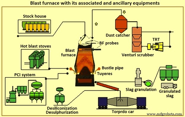
Abb. 1 Hochofen mit zugehöriger und zusätzlicher Ausrüstung
Die BF-Eisenherstellung besteht aus einem System, das aus mehreren Komponenten besteht, die harmonisch funktionieren. Die richtige Anwendung und der richtige Betrieb dieser Komponenten ist notwendig, um den Eisenherstellungsprozess zu unterstützen. Die Auswahl spezifischer Komponenten hängt von Faktoren wie bestehenden Bedingungen, physikalischen Beschränkungen, Produktionsanforderungen, Kosten, Zeitplan, Zuverlässigkeit und Wartbarkeit ab. Die gegenseitige Abhängigkeit der Komponenten ist für den erfolgreichen Betrieb des Systems ebenso wichtig wie ihre individuelle Leistungsfähigkeit. Für jeden Bereich oder jede Komponente gibt es wichtige Anforderungen und „normale“ Praktiken. Es gibt auch einige alternative Technologien, die im Handel erhältlich sind und inhärente Vor- und Nachteile haben.
BF wandelt eisenhaltiges Erz in flüssiges Eisen (Rohmetall) um. Mit der BF verbunden sind Koksofenbatterien, die Kohle in Koks umwandeln, sowie Sinter- und Pelletanlagen, die Eisenerz für die BF aufbereiten. Der BF wandelt diese aufbereiteten Rohstoffe in ein höherwertiges Produkt um. Roheisen aus einigen Betrieben der BFs wird in Gießereien zur Herstellung von Gusseisen verwendet. Andere Betriebe produzieren Roheisen mit niedrigerem Siliziumgehalt, das im Stahlschmelzwerk in Stahl umgewandelt wird. Ein Teil des Roheisens wird in den Rohgussmaschinen zu Roheisen verarbeitet. Die Nebenprodukte der BF sind Schlacke, BF-Gichtgas, Flugstaub und Filterkuchen. Diese Nebenprodukte können je nach Nutzungsmöglichkeiten vor Ort positive oder negative wirtschaftliche Auswirkungen haben.
Einige der verschiedenen Aspekte, die jede Überlegung für die Gestaltung oder Neugestaltung von BF beeinflussen, sind (i) Gewinn, (ii) Gesundheit und Sicherheit der Mitarbeiter, (iii) Umweltschutz, (iv) gesetzliche Vorschriften, (v) Bedürfnisse der Markt und nachgelagerte Verarbeitung, (vi) verfügbare Personal-, Konstruktions- und Wartungsressourcen, (vii) sich ändernde Technologien und veraltete Ausrüstung, (viii) verfügbare Rohstoffe, Betriebsmittel und andere Materialien und (ix) so weiter. Jede ernsthafte Einschränkung in einem dieser Aspekte kann die Rentabilität der BF-Einheit (oder sogar eines Stahlwerks) gefährden oder den Bau einer neuen BF ausschließen oder erforderlich machen.
BFs werden normalerweise nach Größe gruppiert. Mini-BFs produzieren weniger als 1.500 Tonnen Roheisen pro Tag (tSM/Tag), kleine BFs produzieren im Bereich von etwa 2.500 tSM/Tag bis 5.000 tSM/Tag, mittlere BFs produzieren im Bereich von etwa 6.000 tSM/Tag bis 8.000 tHM/Tag, und große BFs produzieren etwa 9.000 tHM/Tag bis 12.000 tHM pro Tag. In einem integrierten Stahlwerk werden eine Anzahl und Größen von BFs benötigt, um das für die Stahlproduktion erforderliche Roheisen bereitzustellen. Integrierte Stahlwerke mit mehreren BFs sind weniger betroffen, wenn ein BF einer Neuzustellungsreparatur unterzogen wird oder wenn es Probleme mit der Ofensteuerung gibt. Kleine BFs haben kürzere Relining-Reparaturen als große BFs und gelten als einfacher zu bedienen. Die Kosten für heißes Metall von kleinen BFs sind jedoch höher. Das integrierte Stahlwerk muss die minimale Anzahl kostengünstiger Öfen betreiben. In einigen Fällen werden Upgrades durchgeführt, um die Anzahl der in Betrieb befindlichen Öfen zu reduzieren.
BFs werden regelmäßig nach dem Ende ihrer Kampagne neu zugestellt (Zeit zwischen der Neuzustellungsreparatur). In der Vergangenheit ging es dabei um den Austausch der Innenausmauerung des Hauptofens. In jüngster Zeit werden gleichzeitig umfangreiche Umbauten, Austausch und vorbeugende Wartung von Komponenten durchgeführt. Mit dieser Praxis verliert das effizientere Stahlwerk mit weniger großen BFs einen höheren Prozentsatz seiner Produktion während der BF-Zustellungsreparatur als das Werk mit einer größeren Anzahl kleiner Öfen. Um sowohl niedrige Betriebskosten als auch minimale Eingriffe während der BF-Relines zu haben, hat die Industrie daran gearbeitet, die Kampagne der BFs zu maximieren und die Dauer der Relining-Reparatur zu verkürzen. Der gegenwärtige klare Trend in den integrierten Stahlwerken besteht darin, weniger große Öfen zu betreiben und Techniken und Konstruktionen zu verwenden, die die BFs-Kampagne auf unbestimmte Zeit verlängern.
Gleichzeitig hat die Reduzierung der Produktvariabilität an Bedeutung gewonnen und daher wird in Automatisierung investiert, die die Überwachung und Steuerung des Prozesses verbessert. BF-Bediener, Wartungspersonal, Konstrukteure und Forschungspersonal haben moderne Technologie und analytische Methoden auf den BF-Prozess angewendet, um den Prozess besser zu überwachen und zu steuern. Dadurch wurde die Standardabweichung der Roheisenqualität reduziert. Verbesserte Datenerfassungssysteme bieten auch mehr Informationen für Lieferanten und Hersteller. Dies hat die Materialauswahl und das Design der BFs und der zugehörigen Ausrüstung verbessert. Die Kampagnendauer hat sich von 5 auf 10 Jahre auf etwa 20 Jahre erhöht.
BF-Eisenherstellung ist eine über 430 Jahre alte Technologie. Dennoch ist die Verwendung von BF-Roheisen nach wie vor die häufigste Methode, die in den integrierten Hüttenwerken zur Herstellung von Stahl verwendet wird. Heutige integrierte Stahlwerksprozesse verlassen sich darauf, dass der BF planmäßig vorhersagbare Mengen an heißem Metall von gleichbleibender Qualität liefert. Schwankungen in allen Aspekten der Roheisenversorgung haben schwerwiegende Auswirkungen auf die übrigen Stahlproduktionsprozesse. Daher ist die BF weiterhin ein Schlüsselprozess in den modernen integrierten Stahlwerken.
Gelegentlich wird behauptet, die BF-Prozesstechnik sei am Ende ihrer Nutzungsdauer. Das ist nicht so. Die Untersuchung der Betriebsdaten von 23 Jahren (1970 bis 1993) von einem typischen Paar mittlerer BFs hat gezeigt, dass es eine durchschnittliche Produktivitätssteigerung von 3 % pro Jahr gibt (Abb. 2a). Gleichzeitig betrug die durchschnittliche Reduzierung der Kraftstoffrate 1 % pro Jahr (Abb. 2b). Außerdem wurde die produktive Zeit zwischen der BF-Zustellung (der Kampagne) durch Verbesserungen bei Ausrüstung, Materialien und Design verlängert. Infolgedessen haben sich die inflationsbereinigten Gesamtkosten für die Herstellung von Roheisen noch stärker verbessert, als es die Betriebsdaten vermuten lassen. Daher ist die BF-Prozesstechnologie nicht tot, obwohl es sich um eine über 430 Jahre alte Technologie handelt. Sie schreitet in allen Bereichen noch immer mit beachtlicher Geschwindigkeit voran. Die BF bleibt auch heute noch eine dynamische Wissenschaft, die von sich ständig verbessernden Technologien unterstützt wird.
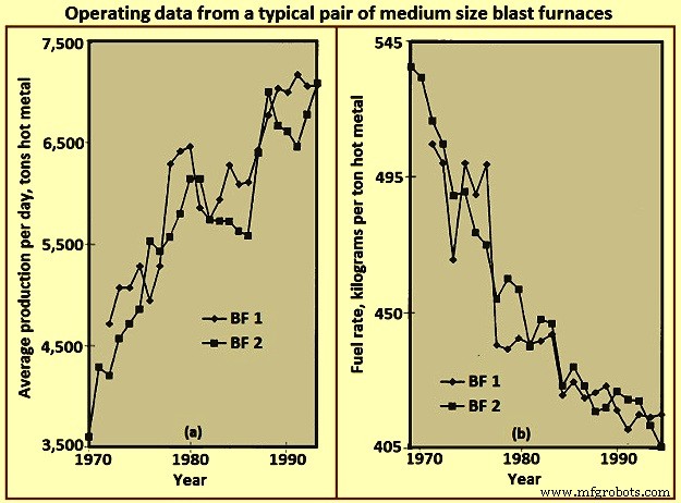
Abb. 2 Betriebsdaten eines typischen Paars mittelgroßer Hochöfen
Layout des BF
Das Layout eines BF ist im Wesentlichen eine Übung zur Integration der Ausrüstung, die benötigt wird, um die verschiedenen Materialien zu handhaben, die zur Herstellung von Roheisen und den resultierenden Produkten und Nebenprodukten benötigt werden. Das effizienteste Design berücksichtigt den gesamten Prozess und seine Effektivität wird sowohl vom Standpunkt der anfänglichen Kapitalinvestition als auch der laufenden Betriebskosten beurteilt. Das BF-Ladenlayout hängt von mehreren Faktoren ab, wie z Standorte, (vi) Mengen-/Flussanforderungen für Roheisen, (vii) Art und Größe der Lieferflotte für Roheisen und (viii) so weiter. Abb. 3 zeigt ein vereinfachtes Layout einer BF-Anlage.
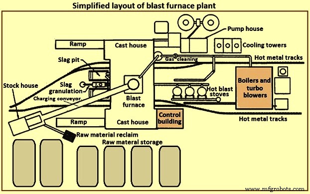
Abb. 3 Vereinfachtes Layout einer Hochofenanlage
Eine BF-Anlage besteht typischerweise aus mehreren Abschnitten. Diese Abschnitte sind (i) Rohstofflagerung, -handhabung und -rückgewinnung, (ii) Lagerhaus, (iii) Beschickungssystem, (iv) eigentlicher Hochofen, (v) Gießhaus, (vi) Schlackenverarbeitung und -handhabung, (vii) Handhabung von Roheisen, (viii) Heißwindöfen und Heißwindsystem, (ix) Gasreinigungsanlage, (x) Versorgungseinrichtungen, (xi) Automatisierungs- und Steuerungssystem, (xii) Wartungseinrichtungen und (xiii) Personalunterstützungseinrichtungen.
Lagerung und Handhabung von Rohstoffen
Rohstoffe wie Eisenerz, Sinter, Pellets, Zuschlagstoffe, Kohle und Koks usw. werden entweder von externen Quellen bezogen oder im integrierten Stahlwerk produziert. Diese Rohstoffe müssen ausreichend kontrolliert gelagert werden, um den BF-Betrieb zu unterstützen. Bei vorhersehbaren Lieferausfällen oder unvorhersehbaren Störungen wird Speicherkapazität benötigt. Bei möglichen Änderungen der Bezugsquelle bestimmter Rohstoffe kann zusätzliche Lagerkapazität erforderlich sein. Aufgrund unterschiedlicher physikalischer oder chemischer Eigenschaften ähnlicher Materialien sind getrennte Lagerorte erforderlich. Das Mischen ähnlicher Materialien kann zu Prozesssteuerungs-/metallurgischen Problemen führen. Die Lagerstapel sind zu trennen, um eine Vermischung der ungleichen Materialien zu verhindern. Die Halden sind auf vorbereitete Betten zu legen, damit die Bediener der Rohstoffrückgewinnungsanlagen zwischen Primär- und Fremdmaterial unterscheiden können. Stapel werden ausgelegt, um die Materialverschlechterung zu minimieren und um zu verhindern, dass Feinstaub vom Wind aufgenommen wird. Wassersprays und Cocooning-Mittel können verwendet werden, um die Staubaufnahme/-abtragung durch Winde zu minimieren.
Für das Ablegen und Abrufen von Rohmaterial stehen mehrere unterschiedliche Techniken zur Verfügung. Zu den Absetztechniken gehören Waggonkippen, Erzbrücken, Stapelförderer, Kratzer usw. Zu den Rückholtechniken gehören Schaufelrad-Rücklader, Bieger-Rücklader, Frontlader, Kratzer, direkt von Behälter- oder Stapelböden usw. Es ist offensichtlich, dass das Ablegen und Zurückholen Systeme sind so zu dimensionieren, dass sie den für die BF-Anlage erforderlichen Durchsatz sicherstellen.
Lagerhaus
Das Vorratshaus ist das Lager des BF-Betreibers zur direkten Beschickung des Ofens mit dem Möller. Für die Beschickungsmaterialien der BF sind jeweils Vorratsbehälter vorgesehen. Für ähnliche Materialien (z. B. Sinter, Pellets) mit unterschiedlichen metallurgischen Eigenschaften werden einzelne Behälter bereitgestellt. Das Lagerhaus stellt bei kurzfristigen Versorgungsstörungen aus den Rohmateriallagern ausreichend Kapazität für die verschiedenen Möller zur Verfügung. Typische Durchsatzkapazitäten von Vorratsbehältern im Falle eines Verlusts der Rohmaterialzufuhr sind (i) Koks – 2 Stunden bis 8 Stunden, (ii) eisenhaltige Materialien (Erz, Sinter und Pellets) – 4 Stunden bis 16 Stunden und Flussmittel und andere verschiedene Materialien – 8 Stunden bis 24 Stunden. Diese Kapazitäten basieren auf der Nennproduktion des Ofens und variieren je nach Zuverlässigkeit und Zugriffszeit für ihren Austausch aus dem Bestand oder von einem Lieferanten.
Belastungsmaterialien neigen dazu, sich aufgrund von klimatischen Bedingungen und wiederholter Handhabung zu zersetzen. Je höher die Anzahl der Handhabungen des Materials ist (Halde, Rückgewinnung, Deponierung, Förderrinnen, Erzbrückenkübel usw.), desto höher ist der Anteil an Feinanteilen im Möller. Der BF-Prozess benötigt eine kontrollierte Permeabilität und somit eine kontrollierte Belastung. Die Beschickung mit übermäßig viel Feingut, entweder normalerweise während der gesamten Beschickung oder konzentriert über bestimmte kurze Beschickungsperioden, kann den BF-Prozess stören und die Ofenausrüstung beschädigen. Das Vorratshaus bietet die letzte vernünftige Gelegenheit zum Entfernen von Feinanteilen vor dem Einbringen in den Ofen. Nach den Koks-, Erz-, Sinter- und Pelletslagerbunkern werden, wo immer möglich, Schwingsiebe installiert, um den Großteil des Feingutes zu eliminieren. Das entfernte Feingut wird zum Recycling gesammelt. Einige BF-Bediener belasten bestimmte Bereiche im Ofen, um die lokale Ofendurchlässigkeit anzupassen und die Wärmelasten an den Ofenwänden zu kontrollieren.
Im Vorratshaus sind häufig Feuchtigkeitsmesser vorgesehen, um die dem Ofen zugeführten tatsächlichen Wassermengen zu überwachen. Diese Information erlaubt eine Anpassung der Beschickungsmengen an die unterschiedlichen Umgebungsbedingungen (z. B. höhere Koksfeuchte während der Regenzeit).
Da zur Unterstützung des kontinuierlichen Betriebs des BF unterschiedliche Arten und unterschiedliche Mengen des Beschickungsmaterials benötigt werden, müssen die Beschickungsmaterialien in einer bestimmten Reihenfolge bereitgestellt werden (die selbst häufig geändert werden kann, um die sich ändernden Betriebsparameter des Ofens zu unterstützen). Daher muss das Lagerhaus mit einer zuverlässigen Ausrüstung zum Extrahieren und Zuführen genauer Mengen spezifischer Belastungsmaterialien ausgestattet werden, um einen spezifischen Zeitplan einzuhalten. Abb. 4 zeigt eine vereinfachte Geräteanordnung im Lagerhaus.
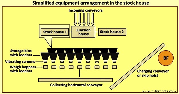
Abb. 4 Vereinfachte Geräteanordnung im Lagerhaus
Früher war der gebräuchlichste Stockhaustyp der Highline-Typ. Dieser Lagerhaustyp befindet sich direkt neben dem Ofen. Schienenfahrzeuge oder Brückenkräne beschicken den Vorratsbehälter, während die Vorratsbehälter direkt zu einem fahrenden Waggon beschickt werden. Ein Bediener des Waagenwagens steuert manuell das Entladetor des Behälters, um bestimmte Materialmengen in den mit einer Waage ausgestatteten Trichter zuzuführen, der sich im Waagenwagen befindet. Nach dem Sammeln der richtigen Materialarten und -mengen bewegt der Bediener den Wiegewagen in eine Position über der „Absetzgrube“ und entleert die Last durch eine Rutsche in einen bereitstehenden Absetzwagen. Der Absetzwagen wird dann auf die Ofenspitze gehoben.
Der Highline-Lagerhaustyp hat in Verbindung mit einem maßstabsgetreuen Wagen nur wenige Optionen für die Bereitstellung von Sieben für eisenhaltige Chargen (Erz, Sinter und Pellets) geboten. Mit zunehmender Kenntnis des BF-Prozesses haben sich strengere Anforderungen an die Belastung entwickelt. Das Konzept der „technischen Belastung“ ist heute in der Branche allgemein anerkannt. Es wird normalerweise akzeptiert, dass der Flexibilität und Anpassungsfähigkeit des Highline-Lagerhauses Grenzen gesetzt sind, um diese Anforderung zu unterstützen. Daher wurde der Highline-Typ des Lagerplatzes durch das automatisierte Förderband-Lagerhaus für die Beschickung des BF mit Einsatzmaterialien ersetzt.
Das automatisierte Lagerhaus besteht normalerweise aus zwei unterschiedlichen und unterschiedlichen Typen. Der erste Typ ist der Ersatz des Waagenwagens unter den Rohstoffbehältern durch ein Beschickungs- und Förderbandsystem. Für jede Art von Rohstoffen (Koks, eisenhaltige Materialien und Flussmittel und Zusatzstoffe usw.) sind getrennte Förderer vorgesehen, über denen Reihen von Vorratsbehältern angebracht sind, mit Vibrationszuführungen, um Abfallmaterialien von Vorratsbehältern auf Förderer zu entladen. Für die koks- und eisenhaltigen Materialien befindet sich am Austrag jedes Förderers ein Vibrationssieb, um das Material zu sieben und das gesiebte Material in die Wägebehälter zu führen. Diese Art von System beschickt weiterhin Wägebehälter vor den Absetzwagen.
Der zweite Typ des automatisierten Lagerhauses ist eine große Struktur von Lagerbehältern, die vollständig über der Erde und ziemlich weit vom BF entfernt gebaut wurden. Dies wird normalerweise für die BFs durchgeführt, bei denen ein Bandförderer verwendet wird, um die Beschickungsmaterialien an die Oberseite des Ofens zu befördern, anstatt die Absetzwagen. Die Befüllung der Vorratsbehälter erfolgt in der Regel über ein Förderbandsystem. Aus den Vorratsbunkern werden die Rohstoffe über Schwingrinnen und Förderbänder in Wiegetrichter gezogen. Die Wiegebehälter wiederum geben das Material über ein Sammelband auf das Hauptband ab. Die Wägetrichter sind so programmiert, dass sie die Rohstoffe in der richtigen Reihenfolge auf das Hauptförderband zum oberen Ende des Ofens wiegen.
Die Bereitstellung eines automatisierten Vorratshauses kann eine effizientere Zuführung von Rohmaterial zum Vorratshaus und eine effizientere Auswahl, Siebung, Wägung und Lieferung der Beschickung zum Ofen ermöglichen. Das automatisierte Magazin kann direkt neben dem Beschickungswagen des Ofens oder entfernt vom Ofen angeordnet sein, um über ein Förderband beschickt zu werden.
Die Automatisierung des Lagerhauses hat die Produktionskapazität erheblich gesteigert, die Betriebseffizienz verbessert und durch Bediener und Ausrüstung verursachte Betriebsabweichungen eliminiert. In der Praxis kann ein modernes, automatisiertes Lager jedoch recht komplex sein. Das Lagerhaus selbst kann von Förderern beschickt werden, die wiederum auf Stolperförderer entladen werden, um Materialien auf verschiedene Behälter zu verteilen. Die Anordnung von Förderbändern und Ausrüstung im Lagerhaus kann auf viele Arten angeordnet werden. Die Platzierung des Lagerhauses neben dem Ofen führt häufig zu einer Überlastung des Layouts und schränkt die Flexibilität für zukünftige Änderungen ein.
Hebesystem
Die Ladegüter werden normalerweise mit Hilfe von Absetzwagen oder Förderbändern auf die BF-Spitze gehoben.
Autoheber überspringen – Die Verwendung von Skip Cars für BF hat sich aus der Bergbauindustrie entwickelt. BF Absetzwagen sind auf den Ofendurchsatz ausgelegt. Offensichtlich haben mehrere Faktoren wie Hubkapazität, Design der Skip-Brücke usw. ihre eigenen Einflüsse oder Einschränkungen auf die Skip-Größe.
Normalerweise arbeiten zwei Skips in entgegengesetzter Weise (um die benötigte Hubkraft zu reduzieren) an einem gemeinsamen Hebezeug. Skips fahren auf Schienen auf einer Skip-Brücke, die normalerweise mit einer Neigung von 60 Grad bis 80 Grad zur Horizontalen installiert ist. Die volle Mulde beschleunigt langsam, wenn sie die Muldengrube verlässt, beschleunigt so schnell wie möglich und erreicht den größten Teil des Aufzugs mit maximaler Geschwindigkeit. Das Hebezeug verlangsamt den Absetzkipper, wenn er sich der Oberseite der Absetzbrücke nähert. Die Räder der Mulde werden durch die Kipp- und Hornschienen geführt, wenn die Mulde in die Beschickungseinrichtung des Hochofens gekippt wird. Wenn der Hubcontainer die endgültige Abladeposition erreicht und dort stoppt, erreicht der leere Container (der mit der gleichen Geschwindigkeit nach unten fährt) gerade den Boden seiner Fahrt in die Containergrube und wartet auf das Befüllen. Das Skip-Beschickungssystem ist eine zuverlässige und effektive Technik, um die Möller an die Ofendecke zu liefern. Allerdings mangelt es dem Bediener an Flexibilität, da die Mulden nur eine bestimmte Materialmenge aufnehmen können (Überladung führt zu Überfüllung oder zu hohen Hublasten) oder ineffizient werden, wenn kleine Volumina mit spezifischer Last benötigt werden. Abb. 5 zeigt schematisch das Heben von Skip-Cars.
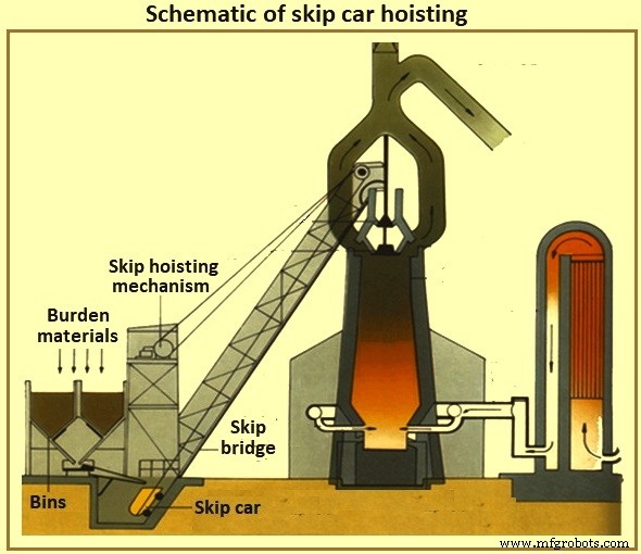
Abb. 5 Schematische Darstellung des Hebens von Skip-Cars
Ofenbeschickungsband – Mit der Fördertechnik des Lagerhauses ist die Fördertechnik der Hebeanlage gekommen. Heutzutage ist es üblich, dass die Vorratshäuser vom Ofen entfernt angeordnet sind und ein großes Förderband die Beschickung zur Ofenoberseite trägt. Wenn die Ofendecke etwa 60 Meter hoch ist, dann muss ein Förderband mit einer Neigung von 8 Grad zur horizontalen Position installiert werden, das Lagerhaus muss mindestens 427 Meter vom Ofen entfernt sein. Steilere Bandneigungen werden normalerweise vermieden, um das Zurückrollen des Materials zu minimieren. Es ist normal, verschiedene Materialien direkt über und nach dem Ende einer Eisencharge auf das Förderband zu laden, um die Eisenmaterialien an Ort und Stelle zu halten, bis sie die Ofenoberseite erreichen.
Beschickungssystem an der Ofenoberseite
Der eigentliche Ofen wird mit Überdruck betrieben. BF-Gas, das teilweise aus Kohlenmonoxid, Kohlendioxid und Stickstoff besteht, wird durch den BF-Prozess zusammen mit großen Mengen an mitgerissenem Staub erzeugt. Der BF-Bediener muss aufgrund der Prozessvorteile den oberen Druck aufrechterhalten und die Gase und den Staub zurückhalten (sowohl für den Brennwert als auch für Umweltschutzzwecke). Der Bediener muss jedoch regelmäßig Beschickungsmaterial in die Oberseite des Ofens einbringen, um den internen Prozess wieder aufzufüllen, ohne den Druck der Ofenoberseite zu verlieren.
Glockenförmiges Oberteil – Seit einigen Jahren ist der zweiglockenförmige Aufsatz die häufigste Form des Ofenaufsatzes (Bild 6). Wenn die Beschickung die Ofenoberseite erreicht (mit einem Behälter oder einem Förderer), fällt sie in einen Aufnahmetrichter und in den kleinen Glockentrichter. Die kleine Glocke (kegelförmiger Stahlguss mit einem Durchmesser von etwa 2,6 Metern und einer Höhe von 1,4 Metern für 5.000 tHM pro Tag BF) senkt sich und lässt die Last in den großen Glockentrichter fallen. Die kleine Glocke wird angehoben und dichtet gegen einen festen Sitz an der kleinen Glocke. Je nach Volumen der großen Glocke werden zusätzliche Möllerladungen durch die kleine Glocke in die große Glocke sequenziert. Die große Glocke ist während dieses Vorgangs geschlossen geblieben und versiegelt den Ofen. Wenn die richtige Anzahl von Ladungen der Last gesammelt wurde, senkt sich die große Glocke (konisch geformter Stahlguss mit einem Durchmesser von etwa 5,5 Metern und einer Höhe von etwa 3,5 Metern für einen BF von 5.000 tHM pro Tag) und lässt die Last in die Glocke gleiten die Oberseite des Ofens richtig. Nach dem Entladen wird die große Glocke angehoben und dichtet gegen die Unterseite des großen Glockentrichters ab. Abb. 6 zeigt Aufladesysteme vom Glockentyp BF.
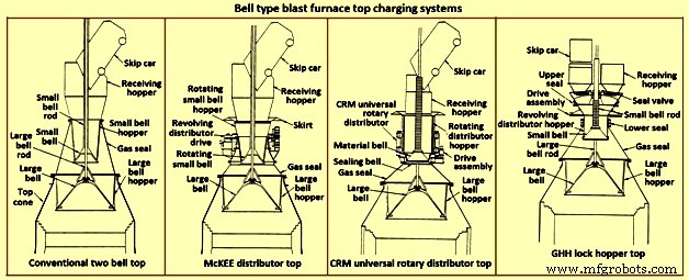
Abb. 6 Haubenhochofenbeschickungssysteme
Offensichtlich ist die Beschickungsverteilungssteuerung mit dem Ofen für diese Art von Aufsatz dadurch begrenzt, wie gleichmäßig die Beschickung auf der großen Glocke platziert wird (das Überspringen führt zu einer ungleichmäßigen Platzierung der Beschickung in dieser Art von Aufsatz) und durch die fallenden Kurven der spezifische Belastungsmaterialien (d. h. Koks- oder Eisenbelastung), wenn sie gleiten und von der großen Glocke fallen. Außerdem ist der Deckel mit zwei Glocken anfällig für einen Dichtungsverlust der großen und der kleinen Glocke und der Dichtung zwischen der Stange der großen Glocke und dem Rohr der kleinen Glocke. Die Leckage der Glocke entsteht durch den Abrieb durch das über die Dichtungsflächen der Glocke gleitende Füllmaterial. Die Undichtigkeit der Stangenpackung ist das Ergebnis von Abrieb durch Feinanteile entweder innerhalb des Ofens oder durch Ansammlung auf der großen Glockenstange, nachdem die Charge in den Aufnahmetrichter abgeladen wurde.
Um den Verschleiß der großen Glockendichtfläche zu minimieren, wird aus dem Ofen entnommenes BF-Gas zwischen die Glocken eingeführt, um den Raum auszugleichen (wodurch die Druckdifferenz über die große Glockendichtfläche verringert wird). Dieses Gas wird vor dem Öffnen der kleinen Glocke in die Atmosphäre abgelassen, um das Einbringen weiterer Lasten zu ermöglichen. Einige der Optionen, die verfügbar sind, um die Einschränkungen des Systems mit zwei Glocken zu verbessern, sind unten aufgeführt.
Der McKEE-Händler – Der McKEE-Verteiler (Abb. 6) war mehrere Jahre lang die wichtigste Lastverteilungsverbesserung, die für das Oberteil mit zwei Glocken verfügbar war. Es wird jedoch schnell durch andere Technologien ersetzt. Sein Design beinhaltet die Fähigkeit, die kleine Glocke und den kleinen Glockentrichter zusammen zu drehen, während der Absetzwagen entladen wird. Die Last wird gleichmäßig in den kleinen Glockentrichter verteilt, wodurch die gleichmäßige Verteilung der Last auf der großen Glocke verbessert wird. Diese Art von Deckel neigt zu kleinem und großem Glockenverschleiß und damit zu einem Verlust der Dichtwirkung.
CRM Universal-Drehverteiler oben – CRM (Centre Recherches Metallurgiques – Belgien) Universal-Drehverteiler (Abb. 6) wurde entwickelt, um den Verlust der Dichtungswirkung der kleinen Glocke zu eliminieren. Anstelle des normalen Glöckchens werden zwei Glocken (eine Siegelglocke und eine Materialglocke) eingebaut. Auf der Materialglocke ist ein umlaufender Möllerbehälter montiert. Die Dichtglocke befindet sich unterhalb der Materialglocke und dichtet gegen einen festen Sitz ab. Während der Skipentleerung werden der Möllerbehälter und die geschlossene Materialglocke gedreht, um den Behälter gleichmäßig zu füllen. Wenn das Füllen abgeschlossen ist, stoppt die Trichterrotation. Zum Abkippen auf die große Glocke werden Drehtrichter, Materialglocke und Siegelglocke abgesenkt. Die Dichtungsglocke senkt sich unter den festen Sitz. Nach der Hälfte des Absenkvorgangs wird die Trichterabsenkung gestoppt und die Materialglocke und die Verschlussglocke fahren weiter nach unten, bis sie ihre Stoppposition erreichen. Da sich der Spalt zwischen Materialglocke und Trichter öffnet, entleert sich das Möller gleichmäßig in den großen Glockentrichter. Wenn die Beschickung den Spalt verlässt, kommt sie nicht mit der Sitzfläche des Dichtungsventils in Kontakt, wodurch die obere Dichtungsfähigkeit aufrechterhalten wird. Dieser Deckeltyp kann einen Innendruck von 0,2 MPa aufrechterhalten.
Das CRM-Oberteil verbessert die Dichtfähigkeit und Langlebigkeit des Zwei-Glocken-Oberteils. Es bietet jedoch keine dramatische Verbesserung der Ofenlastverteilung gegenüber dem McKEE-Verteiler und beseitigt nicht die Schwachstelle der großen Glockendichtungsfläche.
Das GHH Lock Hopper Top – Der GHH Schleusenaufsatz (Bild 6) ist die Modifikation des Zweiglockenaufsatzes. Es verringert die Abhängigkeit von der großen Glocke, um eine Gasdichtung aufrechtzuerhalten. Die Hinzufügung von Schleusentrichtern mit separaten Verschlussventilen für jede Skip-Dump-Stelle bietet eine zusätzliche Kapazität zum Abdichten der Oberseite. Die große Glocke kann ohne Differenzdruck über ihre Dichtungsfläche betrieben werden (d. h. der Druck an der Ofenspitze ist gleich dem Trichterdruck der großen Glocke). Die Operation ist unten angegeben.
Eine Mulde entleert die Möllerladung durch einen Aufnahmetrichter und ein offenes Verschlussventil in den Schleusentrichter. Das Möller wird auf das rotierende Glockengeläut aufgesetzt und füllt den rotierenden Verteilertrichter oberhalb des Glockengeläuts gleichmäßig aus. Während der Drehung ist eine Dichtung zwischen dem Schleusentrichter und der rotierenden kleinen Glocke geöffnet. Wenn der Mölleraustrag aus dem Behälter beendet ist, werden das Absperrventil und die Dichtung zwischen dem Schleusentrichter und dem kleinen Glockentrichter geschlossen. Ausgleichsgas wird eingeführt und der Schleusentrichter wird auf Ofenkopfdruck gesetzt. Die kleine Glocke wird dann abgesenkt, um die Last in den großen Glockentrichter einzuführen. Die kleine Glocke schließt und der Druck aus dem Schleusentrichter wird zur Atmosphäre abgebaut. Das Verschlussventil auf der gegenüberliegenden Seite (d. h. an der anderen Muldenkippposition) wird geöffnet. Die Plombe zwischen dem Schleusentrichter und dem kleinen Glockentrichter wird geöffnet. Die Drehung der kleinen Glocke und des Trichters beginnt. Die Spitze kann nun die Belastung der anderen Mulde übernehmen.
Diese Art von Aufsatz verbessert die Dichtigkeit und die Langlebigkeit des Zweiglockenaufsatzes. Das Verschlusstrichteroberteil bietet jedoch keine dramatische Verbesserung der Ofenlastverteilung gegenüber dem McKEE- oder dem CRM-Oberteil. Obwohl die große Glocke nicht mehr benötigt wird, um eine Dichtungsfunktion zu erfüllen, ist die Langlebigkeit der Dichtungswirkung der kleinen Glocke immer noch entscheidend.
Bewegliche Rüstung – Der wichtigste Schritt zur Verbesserung der Lastverteilung des glockenförmigen Oberteils war die Entwicklung einer beweglichen Panzerung (Abb. 7). Im Halsbereich des Ofens sind einstellbare Abweiser installiert, um das Möller abzulenken, nachdem es von der großen Glocke rutscht. Die bewegliche Panzerung wird in Abhängigkeit von dem spezifischen Beschickungsmaterial eingestellt, das ausgetragen wird, und davon, wo der Bediener die Beschickung innerhalb des Ofens platzieren möchte.
Mehrere Hersteller bieten verschiedene Arten von beweglichen Rüstungen an. Einzelne Panzerungssegmente können gleichmäßig (gleichzeitig und gleichmäßig) innerhalb des Ofens bewegt werden, um die Beschickung in einem ringförmigen Muster zu platzieren. Andere Arten von beweglichen Panzerungen sind verfügbar, um eine individuelle Steuerung der Panzerplatten bereitzustellen, um ein nicht kreisförmiges Verteilungsmuster zu erreichen.
Einige mit beweglicher Panzerung verbundene Nachteile sind (i) die meisten mechanischen und verschleißenden Komponenten liegen in der rauen Umgebung des oberen Konus des Ofens, (ii) ein gewisser Verlust an internem Arbeitsvolumen ist erforderlich, um einen Abstand zwischen der beweglichen Panzerung und der Design-Stocklinie bereitzustellen (obwohl dieser Bereich des Ofens nicht als ungefähre Produktivitätszone für die Betrachtung des Ofenarbeitsvolumens klassifiziert werden kann, und (iii) begrenzte Fähigkeit, die Last bis in die Mitte des Ofens abzulenken, insbesondere wenn der Lagerbestand bereits hoch ist. Das Walzen Eigenschaft von Pellets negiert häufig die begrenzte Verschiebung der beweglichen Panzerung.
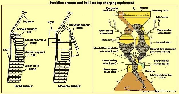
Abb. 7 Stockline-Panzerung und glockenlose Aufladeausrüstung
Bellless Top Charging System – In den frühen 1970er Jahren entwickelte Paul Wurth S.A. aus Luxemburg das Bell-less-Top-Ladesystem (BLT) (Bild 7). Diese Art der Ofendecke ist eine radikale Abkehr von der Glockendecke. Die Beschickung kann innerhalb des Ofens in jedem Muster angeordnet werden, das der Ofenbediener benötigt. Ringförmige Ringe, Spiralen, Segmente und Punktanordnungen sind übliche Muster, die durch synchronisiertes oder unabhängiges Neigen und Drehen einer Beschickungsverteilungsrinne erreichbar sind, die sich am oberen Konus des Ofens befindet.
Die obere Abdichtung des Ofens wird während der gesamten Ofenreise aufrechterhalten. Wartungsarbeiten sind einfach und von kurzer Dauer. Normalerweise besteht die BLT aus einer Annahmerinne oder einem Trichter (zur Aufnahme von Lasten aus den Mulden oder von einem Förderband), einem Schleusentrichter mit oberen und unteren Verschlussventilen, einem Materialfluss-Steuerschieber, einem Hauptantriebsgetriebe für die Rutsche (ein Wasser- oder Gas -gekühlte Einheit zum Drehen und Kippen der Rutsche) und der Lastverteilungsrutsche. Es gibt drei Haupttypen von BLT, nämlich (i) paralleler Trichter, (ii) zentrale Zufuhr und (iii) Kompakttyp.
Typischerweise enthält der parallele Typ zwei Schleusentrichter (die Trichter wurden an einigen Öfen für Durchsatz- und Backup-Zwecke installiert; ein Typ mit einem „exzentrischen“ Trichter wurde für eine Anwendung mit eingeschränktem Spielraum installiert). Seit den frühen 1980er Jahren haben mehrere BFs den Einzelschleusen-Trichtertyp „Zentralbeschickung“ aufgrund seiner Verbesserungen bei der Beschickungstrennung und Beschickungsverteilungssteuerung ausgewählt, was zu einem verbesserten Ofenbetrieb führt.
Für kleine bis mittelgroße Öfen wurde ein „kompakter“ BLT-Aufsatz entwickelt, um die Einführung des BLT (und seiner Vorteile) in Öfen zu ermöglichen, in denen die anderen größeren BLT-Typen aufgrund von Kosten oder physikalischen Einschränkungen nicht verwendet werden können. Die Schritte im BLT-Betrieb für einen Typ mit zentraler Beschickung sind (i) der Möller wird von einem Container oder Förderband durch eine Aufnahmerutsche oder einen Trichter an einem offenen Verschlussventil vorbei in den Schleusentrichter entladen, (ii) nachdem der Möller in der Schleuse aufgenommen wurde Trichter, das obere Absperrventil wird geschlossen und Ausgleichsgas eingeleitet, um den Schleusentrichter auf Ofendruck zu bringen, (iii) das untere Absperrventil öffnet, (iv) die Beschickung aus dem Schleusentrichter entleert wird, wenn der Materialschieber auf eingestellt wurde vorgewählte Öffnung entsprechend dem auszutragenden Möllermaterial, (v) das Möller fällt senkrecht durch den Einfüllschacht mit dem Hauptübersetzungsgetriebe und fällt auf die Möllerrutsche, (vi) die Möllerrutsche leitet das Möller in die gewünschte Richtung point(s) within the furnace, (vii) when the lock hopper is fully discharged (monitored by load cells and / or acoustic monitoring), the lower seal valve is closed, (viii) a relief valve is opened to exhaust the lock hopper to atmosphe re (or through an energy recovery unit), and (ix) the upper seal valve opens and the sequence is repeated.
The advantages of BLT over other top charging systems include higher top pressure capability (i.e. 0.25 MPa), fuel savings, increased production, more stable operation, reduced maintenance in terms of cost and time, increased furnace campaign life, and improved furnace operational control when employing high coal injection rates at the tuyeres.
Gimbal system of charging – The purpose of the Gimbal system of charging is to facilitate controlled distribution of charge material into the BF via a Gimbal type oscillating chute through a holding hopper and variable material gate opening such that the pressurized charging system above can operate independently of the distribution system. It utilizes a conical distribution chute, supported by rings in a Gimbal arrangement, producing independent and combined tilting of the chute axis. The Gimbal distributor, as part of the overall BF top charging system, offers a fully integrated charging solution, generating considerable improvement in BF operation and maintenance cost. The Gimbal system utilizes a conical distribution chute, supported by rings in a Gimbal arrangement, producing independent, and combined tilting of the chute axis.
The Gimbal top incorporates a full complimentary range of furnace top distribution equipment including distribution rockers, upper seal valves, hoppers, lower seal valves, material flow gates and goggle valve assemblies, all discharging through hydraulically driven distribution chutes. The tilting chute is driven by two hydraulic cylinders, mounted 90 degree apart. This type of suspension and drive arrangement results not in a rotation of the tilting chute, but in a circular path by superposition of both tilting motions. Independent or combined operation of the cylinders allows the chute axis to be directed to any angle, or even along any path. Motion is supplied by two hydraulic cylinders, each operating through a shaft, connecting rod, and universal joint in order to drive the Gimbal rings. Through the movement of the hydraulic cylinders, the distribution chute allows precise material distribution with potential for an infinite number of charging patterns at varying speeds. These include ring, spiral, centre, spot, segment or sector charging, providing complete control of material charging into the furnace.
The whole distributor assembly is enclosed in a gas tight housing, which is mounted directly onto the top flange of the BF top cone. The housing contains a fixed inlet chute and a tilting distribution chute supported by rings in a Gimbal arrangement allowing independent and combined tilting of the chute axis. The assembly is made from a combination of stainless and carbon steel material with the fixed inlet chute and tilting chute body lined with ceramic material to give superior wear protection. A closed-circuit water cooling system supplies cooling water through the main shafts, Gimbal bearings, and universal joint bearings in order to cool the moving elements of the Gimbal distribution system.
The key features of the Gimbal design are (i) simple, rugged design, using levers driven by the hydraulic cylinders, (ii) drive cylinders are mounted outside pressure envelope, hence not subject to hot and dusty service conditions, (iii) Gimbal ring arrangement gives simple tilting motion in two planes, which when superimposed gives 360 degrees distribution, and (iv) wear on the tilting chute is equalized around its circumference giving a long extended operational life.
The BF Gimbal top is an automated, computer-controlled pressurized charging system designed to (i) receive charges of ore, coke, and miscellaneous materials in the holding hopper, independently of the distribution system below, (ii) release those discharges, as needed, to a dynamic distribution chute located below the holding hopper, and (iii) distribute material in prescribed patterns to the furnace stock-line in accordance with a predetermined charging matrix. Control of the Gimbal distribution chute is fully integrated into the overall furnace charging software. The system provides a high level of accuracy and control for the Gimbal movements and hence the positioning of the distribution chute. Gimbal material distributor is shown in Fig 8.
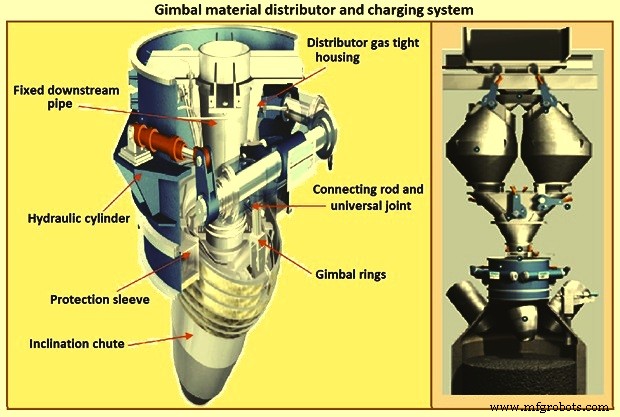
Fig 8 Gimbal material distributor and charging system
Furnace proper
The furnace proper is the main reactor vessel of the BF ironmaking process. Its internal lines are designed to support the internal process. Its external lines are designed to provide the necessary systems to contain, maintain, monitor, support, and adjust the internal process.
The BF process is a counter flow process. The process comprises of (i) burden at ambient conditions is placed in the furnace top onto the column of burden within the furnace, (ii) as the burden descends with the burden column, it is heated, chemically modified, and finally melted, (iii) further chemical modifications occur with the molten material, (iv) the molten products are extracted near the bottom, (v) melting of the burden material and extraction result in the descent of the burden column and the need for replenishment of the burden at the top, (vi) hot blast air is introduced through tuyeres near the bottom, (vii) BF gases are generated in front of the tuyeres and ascend through the burden and chemically modify the descending burden as well as themselves get chemically modified and cooled, (viii) BF gas (and dust) is extracted near the top of the furnace, and (ix) heat is extracted from the vessel in all directions (primarily through the lining cooling system) and along with the BF gas, liquid iron and liquid slag. Fig 9 shows cross section and types of BF.
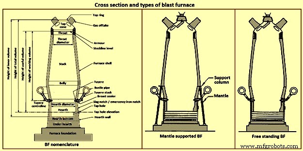
Fig 9 Cross section and types of blast furnace
Furnace type – Furnaces are constructed to be mantle supported or free standing. Mantle supported BFs characteristically have a ring girder (mantle) located at the bottom of the lower stack of the furnace. The mantle is supported in turn by columns which are on the main furnace foundation. The hearth, tuyere breast, and bosh are also supported by the foundation. Furnaces with mantle support column tend to have restricted access and reduced flexibility for improvements in the mantle, bosh, and tuyere breast areas.
Since thermal expansion is a major consideration in furnace shell design, the mantle style of furnace provides an interesting design consideration. The mantle support columns are relatively cool. The mantle tends to maintain a constant height, throughout the furnace campaign with respect to the furnace foundation. Thermal expansion of the stack due to process heat is considered to be based at the ‘fixed’ mantle (i.e. the top of the furnace raises with respect to the mantle). The effective height of the bosh, tuyere breast, and hearth wall shells (supported on the furnace foundation) increases due to the thermal expansion of the shell caused by the process heat. The lower portion of the furnace lifts upwards towards the fixed mantle. Hence, the provision of an expansion joint of some type is needed at the bosh / mantle connection or somewhere appropriately located in the lower portion of the furnace.
Free standing furnaces have been developed to eliminate the column and permit the installation of major equipment and furnace cooling improvements. This furnace type has a thicker shell for structural support. Installation and maintenance of a reliable cooling and lining system is necessary in order to sustain the structural longevity of the shell.
Two variations of the free standing furnace have been used. One type provides for a separate structural support tower to carry the furnace off-gas system and charging / hoisting system load. The other type (while it does employ a separate support tower for shell replacement purposes during relines) uses the furnace proper to support the off-gas system and charging / hoisting system loads. Special consideration to the furnace shell design is to be made regardless of the furnace type. The furnace vessel is subjected to internal pressures from the blast and gas, burden, liquid iron and slag. Dead and live load during all operating, maintenance, and reline stages are to be considered as well.
Furnace zones – The major zones of the furnace proper are (i) top cone, (ii) throat, (iii) stack, (iv) mantle / belly, (v) bosh, (vi) tuyere breast, (vii) hearth walls, (viii) hearth bottom, (ix) foundation.
Top cone – The top cone or dome is the uppermost part of the furnace proper. It supports the furnace top charging equipment, and the BF top gas collection system. Stock rods (stockline recorders or gauges) are normally placed here to monitor the upper level of the burden in the furnace. These devices are the units which provide the permissive or indication signals to charge the next scheduled burden input to the furnace. Typically, they are weights lowered by special winches, or microwave units. Some furnaces incorporate radio-active isotope emitters and detectors mounted in the furnace throat to monitor the burden level. Infrared camera can be installed in the top cone to monitor the BF top gas temperature distribution as it escapes the furnace burden stockline.
The top cone is the coolest zone of the furnace proper but can be exposed to extremely high temperatures if burden ‘slips’ (rapid, uncontrolled burden descent after a period of unusual lack of descent). The newly charged burden falls through this zone and the BF top gas is carried away from this section.
Throat – Steel wear plates or armour are installed in this zone. Here, abrasion of the furnace lining from the charged burden is the prime cause of deterioration. Furnace operators work to maintain the upper level of the burden (the stockline) in this region. Movable armour can be installed in this area in order to deflect the burden falling from a large bell. With the installation of the BLT, wear of the stockline area can be greatly reduced. Some BF users select to eliminate the armour plates and use an abrasion resistant refractory lining instead.
Stack – The stack (sometimes called shaft or the ‘in-wall’) is the zone between the mantle or belly on a free standing furnace and the stockline area. Smooth, uniform lines (the process ‘working surface’) of the stack are essential for uniform and predictable burden descent, BF gas ascent, and stable process control throughout the furnace campaign. Process considerations dictate a larger diameter at the base of the stack than at the top. Typical stack angles are in the range of around 85 degrees from the horizontal.
Mantle / belly – The mantle or belly area provides the transition between the expanded stack and bosh sections. Maintenance of the effectiveness of the cooling / lining system is particularly important for the mantle type furnace in order to protect the mantle structure. Thermal protection is important for the free standing furnace type as well. However, the free standing design is less complicated and more accessible in this area.
Bosh – The bosh area lies between the tuyere breast and the mantle / belly of the furnace. The bosh diameter increases from bottom to top. The inclination of the bosh permits the efficient ascent of the process gases and has been found to be necessary in order to provide the needed zone service life (the process gases are extremely hot and internal chemical attack conditions are severe). Typical bosh angles are in the range of around 80 degrees from the horizontal. Boshes are of two basic types, namely (i) banded and (ii) sealed. They can be cooled by different techniques.
Banded boshes are found in older mantle supported furnaces (they cannot be applied to free standing furnaces). A number of steel bands are placed in incrementally increasing diameters (smallest at the bottom of the bosh and largest at the top) and are tied together with connecting strips. Gap between the bands permits the introduction of copper cooling plates. Ceramic brick lining is to be used as air infiltration results in oxidation of carbon based linings. Gas leakage through the banded bosh can be high. This type is not suitable for BFs with high blast pressure / high top pressure. Banded boshes provide adequate flexibility to eliminate the requirement for a shell expansion joint in the lower portion of the furnace.
Sealed boshes, using continuous steel shell plate instead of separate bands, are employed to permit the use of improved cooling / lining systems, higher furnace operating pressures, and the free standing furnace type. Sealed boshes retain valuable gases with the furnace, hence improving the metallurgical process. As well, the seal bosh, since it precludes air entry into the lining, supports the use of carbon based refractories.
Tuyere breast – Hot blast air is introduced to the furnace through tuyeres (water-cooled copper units) located within the tuyere breast. The number of tuyeres needed depends upon the size (production capacity) of the furnace. The tuyere breast diameter, tuyere spacing, and number of tuyeres are influenced by the expected raceway zone size in front of each tuyere.
Tuyere stocks (Fig 10) convey the hot blast air from the bustle pipe to the tuyeres. The tuyeres are supported by tuyere coolers (water-cooled copper units) which are in turn supported by steel tuyere cooler holders (either welded or bolted to the furnace shell). Special consideration are to be made in the tuyere breast shell and lining design in order to maintain effective sealing of the different components in order to prevent escape and loss of the furnace gases.
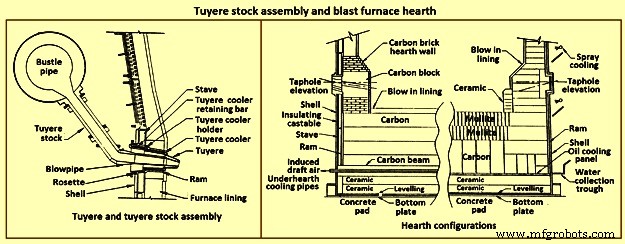
Fig 10 Tuyere stock assembly and blast furnace hearth
Hearth – The hearth (Fig 10) is the crucible of the furnace. Here, hot metal and liquid slag are collected and held until the furnace is tapped. The hearth wall is penetrated by tap holes (frequently called iron notches) for the removal of the collected hot metal and liquid slag. The number of tap holes is dependent upon the size of the furnace, hot metal, and liquid slag handling requirements, physical and capital constraints etc.
Several furnaces are equipped with a slag or cinder notch (normally one per furnace, although some furnaces can have two). The slag notch opening elevation is normally sufficiently higher than the iron notch elevation. In earlier days, when slag volumes were high, the slag was flushed from the slag notch periodically. This simplified the iron / slag separation process in the cast house. More commonly now, however, the slag notch is retained solely for initial furnace set-up procedures or for emergency use in case of iron notch or other furnace operating problems.
Hearth bottom – The hearth bottom supports the hearth walls and is flooded by the iron within the furnace. As the campaign progresses, the hearth bottom lining wears away to a fixed equilibrium point. The remaining refractory contains the process and with sufficient cooling or inherent insulation value protects the furnace pad and foundation.
Cooling system
The application of specific cooling techniques to individual furnace zones is dependent upon several factors such as campaign life expectancy, furnace operational philosophy, burden types, refractories, cost constraints, physical constraints, available cooling media, and preferences etc. Different cooling techniques can be provided for different zones to assist the lining to resist the specific zone deterioration factors. Normally, the provision of adequate cooling capacity is necessary in each of the applicable furnace zones if the lining system located there is to survive. Where the thermal, chemical, and to some extent the abrasive conditions of the process are extreme, sufficient cooling is to be provided to maintain the necessary uniform interior lines of the furnace and to protect the furnace shell.
Typically, the top cone and throat areas of the furnace are not cooled. The hearth bottom can be ‘actively’ cooled by under hearth cooling (air, water, or oil media) or ‘passively’ cooled by heat conduction though the hearth bottom lining to the hearth wall. The basic cooling options for the balance of the furnace are (i) no cooling (typically the upper portion of the stack is not cooled in several furnaces, (ii) shower or spray cooling, (iii) jacket or channel cooling, (iv) plate cooling, and (v) stave cooling.
Shower or spray cooling – Water is directed by sprays or by overflow troughs and descends in a film over the shell plate. Effective spray nozzle design, numbers and positioning are important for proper coverage and to minimize rebound. Proper deflector plate design is necessary to ensure efficient cooling water distribution and to minimize splashing. Shower cooling is frequently employed in the bosh and hearth wall areas. Spray cooling is normally applied for emergency or back-up cooling, primarily in the stack area. Exterior shell plate corrosion and organic fouling are common problems which can disrupt water flow or insulate the shell from the cooling effect of the surface applied cooling. Water treatment is an important consideration to retain effective cooling.
Jacket or channel cooling – Fabricated cooling chambers or indeed structural steel channels or angles are welded directly to the outside of the shell plate. Water flows at low velocity though the cooling elements in order to cool the shell and the lining. Jacket or channel cooling is frequently applied to the hearth walls, tuyere breast, and bosh areas. Scale build-up on the furnace shell and debris collection in the bottoms of the external cooling elements can compromise the cooling effectiveness. Hence periodic cleaning of the cooling elements is necessary.
The critical area of concern in the cooling schemes mentioned so far is the necessity for the shell plate to act as a cooling element. If extreme heat loads are acting upon the inside face of the shell, then there exist an extremely high thermal gradient across the shell. This effect results in high thermally induced shell stresses and eventual cracking. The cracks start from the inside of the furnace and propagate to the outside. The cracks remain invisible (other than a ‘hot spot’) until they fully penetrate the shell plate. Through cracking of the shell plate results in the leak of the BF gas, exposed shell carburization, and disruption of the cooling effect (particularly spray or shower cooling). Shell cracking into a sealed cooling jacket or channel is difficult to locate and can result in long furnace outage time for repair. Entry of water into the furnace (frequently when the furnace is off-line and internal furnace gas pressure cannot prevent entry of cooling water though shell cracks) can have detrimental effect upon the furnace lining. Water in the furnace can be potentially dangerous due to explosion risk (steam or hydrogen). Since shower and jacket cooling rely on the shell plate to conduct the process heat to the cooling media, the plate and stave cooling are configured to isolate the shell from process.
Plate and cigar cooling – Installation of cooling elements though the shell of the furnace (Fig 11) has been a major furnace design improvement resulting in effective cooling of the furnace lining and protection of the shell plate. Cooling is provided along the length of the cooling element penetration into the lining. The inserted elements provide positive mechanical support for the refractory lining. Typical cooling plate manufacture is cast high conductivity copper. Single or multiple passes of cooling water can be incorporated. Cooling boxes with larger vertical section have been produced from cast steel, iron, or copper.
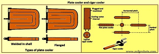
Fig 11 Plate cooler and cigar cooler
Cigar type (cylindrical) coolers (Fig 11) of steel and /or copper have also been successfully used. The philosophy of dense plate cooling (i.e. vertical pitch of 350 mm to 400 mm centre-to- centre, and horizontal pitch of 600 mm (centre-to-centre) has improved the cooling effect and increased lining life.
Copper cooling plates have traditionally been anchored in the shell plate with retainer bars or bolted connections to permit ready replacement if plate leakage occurs. More recently, plates have been designed with steel sections at the rear of the plate for welding directly to the steel shell. While sometimes taking longer to replace, this type provides a positive seal against BF gas leakage. Plate coolers are typically installed in areas above where the liquid iron collects in the furnace. Hence the mid-point of the tuyere breast, right up to the underside of the throat armour is the range of application.
Stave cooling – Cast iron cooling elements (Shannon plates or staves) have been used for several years in the bosh and hearth wall areas. These castings have cored cooling passages of large cross-section. While their service life have been not remarkable in the bosh, multiple campaigns have been normal for the hearth wall. These staves frequently suffered from low flow rates of marginal quality cooling water (scaling and debris deposition / build-up) and sometimes casting porosity. Water leaks into the hearth wall can be a considerable problem.
In the 1950s, the then USSR developed a new type of stave cooler (Fig 12) and ‘natural evaporative stave cooling’. For this design, castings were of gray cast iron containing steel pipes for water passes. The pipes were coated prior to casting to prevent carburization of the cooling pipe and metallurgical contact with the stave body material. The staves were installed in horizontal rows with the furnace and the cooling pipes projected through the shell. Vertical column of staves were formed by the inter-connection of the projecting pipes from one stave up to the corresponding stave in the next row. Staves can be applied to all the walls in the zones below the armour. Staves in the hearth wall and tuyere breast are supplied with smooth faces. Staves in the bosh, mantle / belly and stack normally have rib recesses for the installation of refractory.
Evolution of the stave cooler design has been dramatic. Staves in the higher heat load areas are now typically cast from ductile iron for improved thermal conductivity and crack resistance. While early stave design used castable refractory (installed after stave installation within the furnace), ribs now normally incorporate refractory bricks, either cast in place (with the stave body at the foundry) or slid and mortared in place prior to installation in the furnace. Fig 12 shows stave cooler and generations of stave development.
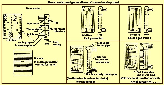
Fig 12 Stave cooler and generations of stave development
Staves are normally expected to retain a refractory lining in front for some time. After loss (expected) of the lining the staves are designed to resist the abrasive effects of descending burden and ascending dirty gas. As well, they are to absorb the expected process heat load and resist thermal load cycling and shock. Four generations of staves (Fig 12) are normally recognized in the industry.
First generation staves are no longer normally used. These staves have four cooling body circuits (with long radius bends which do not effectively cool the stave comers. These staves are made of gray iron castings with castable rib refractory. Second generation staves have four cooling body circuits with short radius bends for improved comer cooling. These staves are made of ductile iron castings with cast-in or glued-in rib bricks. Third generation staves have two-layer body cooling incorporating four or six cooling body circuits (stave hot face) and one or two serpentine cold face circuits (stave cold face) for additional or back-up cooling in the event of hot face circuit loss. These staves have additional edge cooling (top and bottom). The more frequent use of these staves is as cooled ledges to support a refractory lining. These staves have cast-in or mortared-in rib bricks. Fourth generation staves have two-layer cooling (similar to third generation). These staves have cooled ledges and cast-in wall brick lining eliminating the need for a manually placed interior brick lining.
Staves incorporating hot face ledges are more effective in retaining a brick lining than the smoother rib faced bricks. However, once the brick lining disappears, the ledges are very exposed within the furnace. The ledges disrupt burden descent and gas ascent. Exposed ledges tend to fail quickly. They are frequently serviced by cooling water separate from the main stave cooling circuit(s). In this way leaking ledge circuits can be more easily located or isolated. Some stave manufacturers are now providing separate ledge castings so that ledge cracking and loss does not damage the parent staves. As well, there is some present change in philosophy to abandon the application of ledges entirely.
Variations of the basic stave generation types are common. For example, staves of fourth generation type utilizing a refractory castable for the wall ling have been employed successfully. Alternatively, brick linings have been anchored to the stave bodies. Such approaches can be used to substitute for brick support ledges.
A ‘fifth’ generation of staves design has been the developed. It is the copper stave (Fig 13). The development of copper staves was carried out both in Japan and Germany for use in the region of bosh, belly, and lower stack to cope with high heat loads and large fluctuations of temperatures. While Japan has gone for cast copper staves, German copper staves are rolled copper plates having close outer tolerarnces and with drilling done for cooling passages. Drilled and plugged copper staves are typically designed for four water pipes in a straight line at the top and four water pipes in a stright line at the bottom. Materials for internal pipe coils include monel, copper, or steel. Unlike cast iron staves, copper staves are intended to be bonded to the cooling pipe.
The development of the cast-in copper stave has considered the following aspects. As per the first aspect, for the prevention of deformation, appropriate design of the stave length and bolt constrained points is important. The first aspect is that the use of the cast-in steel pipe copper stave with its own design is beneficial for effectively reducing the risk of deformation. Fig 13 shows the constrained points of a rolled copper stave and the cast-in steel pipe copper stave. A rolled copper stave is constrained to the shell by mounting bolts and pins. To prevent the weld at the base of a rising pipe from being damaged by stresses, rising piping is connected to the shell by an expansion joint. Due to this structure, the upper and lower ends of the staves are freely displaced, causing the staves to be easily deformed. The large thermal load which is repeatedly applied to the copper stave in the course of the fluctuation in the BF operations etc., causes plastic strain to be gradually accumulated, and results in large deformation. There are cases in which the deformation at the upper end has reached 50 mm or more and a weld has been broken, under the condition of an overly long stave, an in-appropriate bolt position, or high heat load exceeding the design condition.
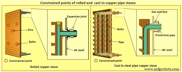
Fig 13 Constrained points of rolled and the cast-in pipe copper stave
Presently, the most popular type of copper stave is the rolled copper stave, the manufacturing process of which involves drilling holes on a copper plate. The water channel ends of these staves are plug-welded. The cast-in steel pipe copper stave, which has been developed, is made by casting bent steel pipes into the copper, a completely different manufacturing process from that of the conventional rolled copper stave. This unique manufacturing method has enabled achieving high energy efficiency and long life of BFs, which cannot be achieved using the rolled copper stave.
Natural evaporative stave cooling (NEVC) is a technique where boiler quality water is introduced into the bottom row of staves and flows by natural mean up the vertical cooling circuits. As the process heat conducts through the stave and cooling pipe into the water, the water in turn heats up. As the water warms, it expands. Since cooler water is being introduced below, the warm water tends to move upwards. At some point in the vertical cooling circuit, the water is at the boiling point. As the water changes its phase to steam, due to the latent heat of vapourization, additional heat is absorbed (driving the phase change). After boiling begins, two-phase flow (water and steam mixture) ascends the cooling pipes to the top of the furnace. Normally located on the furnace top platform are steam separator drums used to extract and vent the steam to atmosphere. Make-up water is introduced to the drum (to replace the discharged steam). The water is piped back by gravity to the furnace bottom and is fed once more to the staves. This cooling technique is very efficient and has low operating costs. There is no pumping equipment. The improvements in this system has been to boost the flow of the cooling water with recirculating pumps (forced evaporative cooling, FEVC) in order to ensure uniform cooling water flow and to cool the recirculating water (forced cold water cooling – FCWC). Both of these approaches have resulted in improved stave and lining life.
Staves provide an excellent protection for the shell plate throughout their service life (which is extended while the interior brick lining remains in place). Stave application has been implemented in all areas of the furnace from hearth wall up to and including the upper stack.
One drawback for conversion of an existing plate cooled furnace to stave cooling can be the cost of a new shell. However, if the existing shell is already in distress and is to be replaced in any event, the conversion cost is not a major factor.
Cast house
The cast house (Fig 14) is the area or areas at the BF where equipment is placed to safely extract the hot metal and liquid slag from the furnace, separate them, and direct them to the appropriate handling equipment or facilities. The hot metal and liquid slag are removed from the furnace through the tap hole. Only infrequently today slag is flushed from the slag notch. The equipment for tap hole is to be reliable and need minimum maintenance. Furnaces typically tap eight times to eleven times per day.
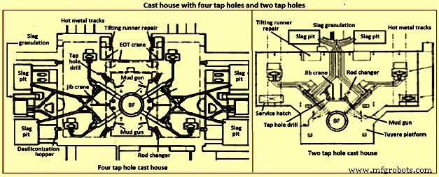
Fig 14 Cast house with four tap holes and two tap holes
Mud gun – The mud gun is used to close the tap hole after tapping is complete. A quantity of the tap hole mass is pushed by the mud gun to fill the worn hole and to maintain a quantity of the tap hole mass (the mushroom) within the hearth. The mud gun is normally held in place on the tap hole until the tap hole mass cures and the tap hole is securely plugged. A hydraulic mud gun uses hydraulic power to swing, hold, and push the tap hole mass. Typical injection pressure of tap hole mass is of the order of 20 MPa to 25 MPa, permitting it to push viscous mass into the furnace operating at high pressures. The hydraulic gun is held against the furnace with the equivalent of 15 tons to 35 tons of force. This type of mud gun can be swung into place in one motion.
An electro-mechanical gun has three separate electric drives for unit swing, barrel positioning, and ramming. Hence several separate motions are needed for accurate positioning of the mud gun at the tap hole. Tap hole mass injection pressure is in the range of only 5 MPa to 8 MPa. The electro-mechanical mud gun is latched to the furnace to keep it in place during plugging.
Tap hole drill – Tap hole drill is used to bore a hole though the tap hole clay into the hearth of the furnace. A drill unit is swung into place hydraulically and held hydraulically in the working position. A pneumatic motor feeds the hammer drill unit (with an attached drill rod and bit) into the hole. Compressed air is fed down the centre of the drill rod and the drill bit to cool the bit and blowout the removed tap hole mass. When the tap hole drill rod has penetrated into the hearth, the drill rod is retracted and the drill swings clear of the hot metal stream.
Soaking bar technique – The application of the soaking bar practice has improved the tapping process. When the tap hole mass is still pliable after plugging, a steel bar is driven into the tap hole by the tap hole drill. While the bar sits in place during the time between casts, it heats up by conduction from the hearth hot metal. This permits curing of the tap hole mass along its entire length (as opposed to curing with the furnace and setting at the outside near the furnace cooling elements). The cured tap hole mass is more resistant to erosion during tapping, hence improving tap flow rate control. Less tap hole mass is needed to replug the hole. When the tap hole is to be opened, a clamping device and a back hammering device on the tap hole drill extract the rod. The timing for tap hole opening can be more easily controlled (predicted) than by conventional drilling. This feature is important for smooth furnace operation and for scheduling of hot metal delivery to downstream facilities.
Same side tap hole equipment – Mud gun and drills have normally been installed on opposite sides of the tap hole. Design development has permitted installation of these equipments on one side of the tap hole. The drill swings over the mud gun or vice versa. This type of installation facilitates improved access for tap hole and trough maintenance and the improved application of trough and tap hole area flue collection.
With the advent of tuyere access platforms to facilitate tuyere and tuyere stock inspection and replacement, the headroom available for the tap hole equipment has diminished. However, same side tap hole equipment installations can be achieved with low headroom (for example 2.2 metres).
Trough and runner system – Typical hot metal and slag tapping rates are in the range of 4 to 6 tons per minute and 3 to 5 tons per minute, respectively. The trough and runner systems are to be designed to properly separate the iron and slag and to convey them away from the furnace for flow rates within the normal flow rate range and for unusual peak flow rates.
The hot metal trough (Fig 15) is a refractory lined tundish located in the cast house floor and designed to collect iron and slag after discharge from the furnace. The hot metal flows down the trough, under a skimmer and over a dam into the hot metal runner system. The hot metal level in the trough is dictated by the dam. Proper dam design submerges the lowest portion of the skimmer in the hot metal pool. The slag, being lighter than the hot metal, floats down the trough on top of the hot metal pool. Since it cannot sink into the hot metal and through the skimmer opening, it pools on top of the hot metal until sufficient volume collects to overflow a slag dam and run down the slag runner. At the end of the tapping, the slag runner dam height is lowered to drain off most of the slag. The residual hot metal is retained in the trough to prevent oxidation and thermal shock of the trough refractory lining.
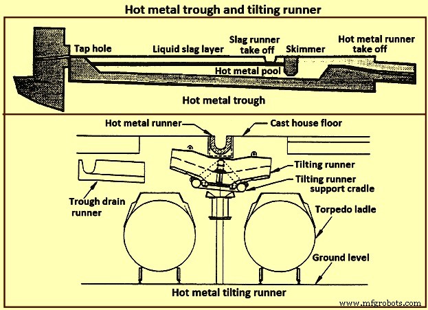
Fig 15 Hot metal trough and tilting runner
When maintenance of the trough lining is needed, the hot metal pool can be dumped by removing the hot metal dam, or by opening a trough drain gate, or by drilling into the side of the trough (at its lowest point) with a drain drill. The trough bottom is normally designed with a 2 % (minimum) slope for effective draining. Trough cross-section and length design are important for effective iron and slag flow pattern, retention, and separation. A good trough design results in hot metal yield improvements. Effective trough lining and cooling techniques are important for lining life, hot metal temperature, and cast house structural steel and concrete heat protection considerations. Troughs traditionally were contained in steel boxes ‘buried in sand’ in the cast house floor system. Improved trough design incorporates forced or natural air convection or water-cooling.
Cast house practice needs the runners to be as short as possible. This minimizes temperature loss of hot metal and reduces runner maintenance and flue generation. Shorter runners can also result in reduced capital expenditure for cast house building installation or modification. Since the runners are to slope away from the furnace, the cast house floor normally follows the same slope as the runners.
Slag runners are normally designed with a 7 % (minimum) slope. Slag can be directed to (i) slag pots for railway or mobile equipment haulage to a remote site for dumping, (ii) slag pits adjacent to the furnace for air cooling and water quenching prior to excavation by mobile equipment, and (iii) granulation facilities adjacent to the furnace for conversion of the liquid slag to granulated slag. Granulation units are provided with systems to eliminate flue emissions associated with environmental issues.
Hot metal runners are normally designed with a 3 % (minimum) slope. Hot metal is normally directed to hot metal transfer ladles (torpedo cars / open top ladles) for movement to the steel melting shop or pig casting machines. While normal practice used is to have one iron runner system with diverter gates directing the hot metal to different pouring positions, each with a ladle. Application of the tilting runner practice has been beneficial. A tilting runner is normally with an electrical motor-driven actuator (with a manual hand wheel back-up), and is tilted at around 5 degrees to divert the hot metal. A pool of hot metal is held in the tilting runner to minimize splashing and refractory wear. When one hot metal ladle has been filled, the runner is tilted to the opposite side to fill the other ladle. If needed, a locomotive removes the filled ladle and spots an empty ladle in its place. This operation can be done without plugging the furnace. When the tapping is finished, the tilting runner is tilted an additional 5 degrees to dump its pool of hot metal into the ladle.
Modern cast house design includes flat floors, where the runner is fully covered and is fitted flush with the floor. This allows safer and easier use of mobile vehicles in the cast house area. The use of radio controlled equipment and other devices have helped to reform cast house work, and these, along with effective emission control systems, have improved working conditions. As the BF hearth diameter is increased, there is a resulting need to increase the size of the cast-house. Large BF are normally designed with four tap holes (Fig 14). With a four top-hole configuration, the cast-house arrangement needs to provide sufficient space for movement around the floor itself. There is no design issues associated with this requirement as long as there is the necessary space provided in the site plan. Increasing the size of the cast-house in terms of floor plan does not represent a radical change in design philosophy which can pose a challenge the furnace designer. An efficient and strictly controlled tapping is necessary for ensuring a stable operation and high productivity of the BF.
Emission control
Fume collection requirements and applications appear to vary considerably around the globe. BFs presently have full, partial, or even no cast house fume collection system. Exhaust fan and bag house capacity of the order of 9,000 cubic meter per minute (cum/min) to 11,500 cum/min (depending upon operation and design practices) is typical for full flue capture of a two tap hole cast house installation (for trough runners and tilting runners).
Proper design and application of flue collection runner covers can facilitate cast house access (i.e. flat floor configuration using steel slabs or plates) for personnel and mobile equipment crossover. Runner covers can also reduce hot metal temperature loss and improve runner refractory longevity.
Some furnaces use flame suppression which eliminates the oxygen in the air directly over the trough and iron runners. Products of combustion prevent oxidation of the hot metal surface reducing visible particulate and flues.
Other aspects of BF design
It is necessary that complete study of every element in the process chain, from raw materials delivery to hot metal consumption is made to ensure that there are no ‘bottle necks’ in the system which can prevent the furnace from meeting the goals of its installation. While designing the BF, thought process is to be used to develop the furnace design and some alternatives are to be considered before freezing the design. During the designing of the furnace, those furnace equipments are to be selected which best meet the needs of the furnace operation.
The furnace design is to ensure (i) the furnace is capable of meeting the operational goals of production, productivity (tons per day per cubic metre of working volume), specific consumptions (kilograms per ton of hot metal), and product quality in cost effective manner, (ii) the furnace has the flexibility to accept and absorb the changes in the quality of the raw materials, and (iii) the furnace is capable of achieving the desired campaign life both with respect to time and the total production.
Financial justification is the over-riding consideration for the design. For this purpose, the economic study is to be very extensive. Further, the furnace design is to include latest technological developments so that the furnace does not become technologically outdated during its entire campaign.
The working volume of the furnace is the internal volume of the furnace calculated between the tuyeres and the stock line. Hearth productivity of the furnace is rated in tons per day per cubic metre of active hearth volume. Active hearth volume is the internal volume of the furnace calculated between the tuyeres and the tap hole. Active hearth volume is a measure of the holding capacity of the furnace for the liquids produced in the working volume (above the tuyeres). Hence, the tons per day per cubic metre of active hearth volume is a measure of the specific capacity (through-put per unit volume) of the hearth of the BF.
The design of the hearth is very important since it has a strong effect on the furnace operation. The furnace operation gets affected since the hearth liquid levels change rapidly which cause variations in gas flow pattern, gas utilization, and blast pressure. Also, because of these rapid changes in liquid level, there can be jamming / burning of the tuyeres which affect the blowing of the furnace.
The furnace hearth volume also determines the controls the operator is to exercise during furnace operation. For a very good hearth liquid level control, the high through-put furnace need around 90 % time spent in tapping. To make this time of tapping possible, cast floor is to be designed properly.
The furnace lining and cooling system needs special attention so that it does not pose any problem during the entire campaign of the BF. The selection of refractories, cooling elements, and internal furnace geometry is very important in this respect. Copper staves in this respect are expensive but they are very economical in comparison to the alternatives. Carbon lining of the hearth is very important for the long life of the hearth. The refractory lining thickness of the stack has implication on the furnace working volume.
The production needed normally determines the size of the BF. However, for the sizing of the BF, the raw materials, the product chemistry, and even operating philosophy are important. While the furnace size has implication on the capital cost, the productivity improvement has implication on the operating cost. The specific productivity of the furnace is to be determined for the determination of the size of the BF needed to produce the required quantity of hot metal. From the wide range of possible operating rates, the working volume of the furnace is to be calculated. Productivity and hence the furnace size is also to be based on the fuel rate. The fuel rate is dependent on the quality of raw materials, hot blast parameters, hot metal quality, and the operating philosophy.
The size is the most important factor for the determination of the BF productivity. However, there are other factors which also influence the BF productivity. The most important of these factors include (i) hot blast temperature and pressure, (ii) high top pressure, (iii) oxygen enrichment of the air blast, (iv) injection of auxiliary fuel at the tuyere, (v) prepared burden (sinter, pellets etc.), (vi) Fe content of the ferrous burden, (vii) ash in coke, (viii) quality of the coke, (ix) moisture content of the burden, (x) direct charging of fluxes (lime stone, dolomite etc.) in the BF, (xi) content of fines in the burden, (xii) quality of hot metal to be produced, (xiii) burden distribution control in the furnace, and (xiv) level of automation and control in the furnace.
The availability of furnace equipment, provision of stand-by equipment, and the maintenance philosophy are important factors which have high influence on the annual production from the BF. Further, incorporation of safe and healthy working practices during the operation of BF in the design of the BF is important which has a high influence on the furnace productions. In this regards, safety interlocks are to be provided at all the places where there exist a chance of unsafe operating practices to take place.
Herstellungsprozess
- Hochofenschlacke und ihre Rolle beim Ofenbetrieb
- Wichtige Aspekte der Konstruktion von Hochöfen und zugehörigen Zusatzausrüstungen
- Prozessautomatisierungs-, Mess- und Steuerungssystem für Hochöfen
- Erzeugung und Nutzung von Hochofengas
- Hochofenproduktivität und die Einflussparameter
- Hochtonerdeschlacke und Hochofenbetrieb
- Kühlsystem für Hochöfen
- Hochofen-Gießhaus und sein Betrieb
- Hochofen und sein Design
- Eisenerzeugung durch Hochöfen und Kohlendioxidemissionen